EP0342641A1 - Zündkerze - Google Patents
Zündkerze Download PDFInfo
- Publication number
- EP0342641A1 EP0342641A1 EP89108856A EP89108856A EP0342641A1 EP 0342641 A1 EP0342641 A1 EP 0342641A1 EP 89108856 A EP89108856 A EP 89108856A EP 89108856 A EP89108856 A EP 89108856A EP 0342641 A1 EP0342641 A1 EP 0342641A1
- Authority
- EP
- European Patent Office
- Prior art keywords
- spark
- insulator
- spark plug
- electrode
- discharge chamber
- Prior art date
- Legal status (The legal status is an assumption and is not a legal conclusion. Google has not performed a legal analysis and makes no representation as to the accuracy of the status listed.)
- Granted
Links
- 239000012212 insulator Substances 0.000 claims abstract description 28
- 239000000919 ceramic Substances 0.000 claims description 6
- 229910010293 ceramic material Inorganic materials 0.000 claims 1
- 230000006835 compression Effects 0.000 description 12
- 238000007906 compression Methods 0.000 description 12
- 239000000203 mixture Substances 0.000 description 12
- 238000002485 combustion reaction Methods 0.000 description 7
- 230000015572 biosynthetic process Effects 0.000 description 4
- 238000013461 design Methods 0.000 description 4
- 239000007789 gas Substances 0.000 description 4
- 230000000694 effects Effects 0.000 description 3
- 239000000126 substance Substances 0.000 description 3
- 230000005684 electric field Effects 0.000 description 2
- 239000003344 environmental pollutant Substances 0.000 description 2
- 230000003628 erosive effect Effects 0.000 description 2
- BASFCYQUMIYNBI-UHFFFAOYSA-N platinum Chemical compound [Pt] BASFCYQUMIYNBI-UHFFFAOYSA-N 0.000 description 2
- 231100000719 pollutant Toxicity 0.000 description 2
- 238000012549 training Methods 0.000 description 2
- 230000007704 transition Effects 0.000 description 2
- 229910000990 Ni alloy Inorganic materials 0.000 description 1
- 238000013459 approach Methods 0.000 description 1
- 238000006243 chemical reaction Methods 0.000 description 1
- 239000002131 composite material Substances 0.000 description 1
- 238000011161 development Methods 0.000 description 1
- 230000018109 developmental process Effects 0.000 description 1
- 238000010586 diagram Methods 0.000 description 1
- 239000007772 electrode material Substances 0.000 description 1
- 239000000446 fuel Substances 0.000 description 1
- 239000011521 glass Substances 0.000 description 1
- 239000000463 material Substances 0.000 description 1
- 238000005259 measurement Methods 0.000 description 1
- 230000008018 melting Effects 0.000 description 1
- 238000002844 melting Methods 0.000 description 1
- 229910052697 platinum Inorganic materials 0.000 description 1
- 238000005381 potential energy Methods 0.000 description 1
- 230000001105 regulatory effect Effects 0.000 description 1
- 229910052709 silver Inorganic materials 0.000 description 1
- 239000004332 silver Substances 0.000 description 1
Images


Classifications
-
- H—ELECTRICITY
- H01—ELECTRIC ELEMENTS
- H01T—SPARK GAPS; OVERVOLTAGE ARRESTERS USING SPARK GAPS; SPARKING PLUGS; CORONA DEVICES; GENERATING IONS TO BE INTRODUCED INTO NON-ENCLOSED GASES
- H01T13/00—Sparking plugs
-
- H—ELECTRICITY
- H01—ELECTRIC ELEMENTS
- H01T—SPARK GAPS; OVERVOLTAGE ARRESTERS USING SPARK GAPS; SPARKING PLUGS; CORONA DEVICES; GENERATING IONS TO BE INTRODUCED INTO NON-ENCLOSED GASES
- H01T13/00—Sparking plugs
- H01T13/46—Sparking plugs having two or more spark gaps
- H01T13/467—Sparking plugs having two or more spark gaps in parallel connection
-
- H—ELECTRICITY
- H01—ELECTRIC ELEMENTS
- H01T—SPARK GAPS; OVERVOLTAGE ARRESTERS USING SPARK GAPS; SPARKING PLUGS; CORONA DEVICES; GENERATING IONS TO BE INTRODUCED INTO NON-ENCLOSED GASES
- H01T13/00—Sparking plugs
- H01T13/20—Sparking plugs characterised by features of the electrodes or insulation
- H01T13/32—Sparking plugs characterised by features of the electrodes or insulation characterised by features of the earthed electrode
-
- H—ELECTRICITY
- H01—ELECTRIC ELEMENTS
- H01T—SPARK GAPS; OVERVOLTAGE ARRESTERS USING SPARK GAPS; SPARKING PLUGS; CORONA DEVICES; GENERATING IONS TO BE INTRODUCED INTO NON-ENCLOSED GASES
- H01T13/00—Sparking plugs
- H01T13/52—Sparking plugs characterised by a discharge along a surface
Definitions
- the invention relates to a spark plug with combined sliding and air spark gaps according to the preamble of claim 1.
- Such a spark plug is known from DE-PS 3 544 176.
- the center electrode extends slightly into the discharge chamber which the insulator forms by extending in the candle-axial direction beyond the center electrode, the insulator, at least in the end region of the center electrode, maintaining a gap to the latter and also the ground electrode , at least in the end region of the insulator, maintains a gap to this.
- the known spark plug according to DE-PS 3 544 176 is still disadvantageous insofar as there is a high voltage requirement of, for example, 30 kV when starting an internal combustion engine in which such a spark plug is used. Since, in the known spark plug, the sliding spark always runs over the ceramic insulator, which is associated with a corresponding wear of the insulator, the service life of the known spark plug is still not optimal.
- the object underlying the invention is therefore to design the spark plug according to the preamble of claim 1 so that it has a relatively low voltage requirement with high energy conversion in the ignitable fuel-air mixture.
- Lean mixtures should preferably also be able to be ignited with the spark plug according to the invention, and the pollutant emissions in the exhaust gases of an internal combustion engine should be kept as low as possible due to the candle geometry.
- the center electrode is thus preferred so that it ends in the end section of the plug body, so that an air spark gap is formed in the front region of the spark plug, and at the same time the discharge chamber forms a prechamber which allows sliding spark discharges.
- the training according to the invention thus taking advantage of a prechamber candle.
- the spark plug according to the invention also has a long service life.
- this means that the form of discharge is determined by the load state of the machine, the dynamic pressure conditions of the compression and the mixture vortex determining the form of discharge. In practice, this means that depending on the pressure conditions, either air spark or sliding spark discharges or partial air spark and partial sliding spark discharges occur during operation of the machine. It should be noted that an air spark discharge is formed at a low compression pressure and that at a high compression pressure the spark discharge prevails on the sliding spark gap provided.
- these forms of discharge have the effect that, in the case of an air spark discharge, the mixture in the main combustion chamber, i.e. is ignited in the machine cylinder and, on the other hand, the ignitable mixture is ignited in the prechamber.
- the chemical energy from the antechamber is also transferred to the main combustion chamber by expansion forces. This additional chemical energy causes additional ignition and thus ensures that the mixture burns safely.
- the spark plug works as a sliding spark plug, the ignitable mixture is ignited in the prechamber.
- the combination of the air spark and sliding spark gaps results in a long service life overall, since the erosion areas on the center electrode or ground electrode and the sliding spark gap are very large. With increasing pressure The base of the sparks then moves deeper and deeper into the discharge chamber along the entire free electrode length.
- the ceramic sliding spark gaps ie the sliding spark gaps on the ceramic insulator, are protected by the ring-shaped ground electrode which surrounds the insulator from the outside in around the end of the insulator.
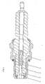
- the embodiment of the spark plug according to the invention shown in FIG. 1 essentially comprises a metallic spark plug body 1 with a screw thread, a ceramic insulator 2, a center electrode 3 and an annular ground electrode 4.
- the insulator 2 is surrounded by the spark plug body 1 together with the ring-shaped ground electrode 4 .
- a prechamber or discharge chamber 5 is provided in the form of a recess, which is preferably of a V-shaped axial section with a cross section widening towards the end of the insulator.
- the ground electrode 4 encircles the insulator 2 at the end of the insulator in a ring from the outside inwards.
- the ground electrode is where the discharge came from mer extending end of the approach encompassing the insulator rounded to avoid electrical field distortions, so that the spark does not take off prematurely from the sliding spark gap in the case of sliding discharges and on the other hand in the case of air spark discharges the spark forms as far forward as possible towards the main combustion chamber, as is more the case will be described later with reference to FIG. 3.
- the center electrode 3 is introduced in the insulator 2 in a pressure-tight manner, for example by melting glass, etc.
- Known materials such as silver, nickel alloys, platinum composite materials or conductive or semiconducting ceramics can be used as the electrode material of the center electrode 3.
- Two-substance electrodes can also be provided.
- the ground electrode 4 is designed so that it acts simultaneously as a seal between the spark plug body 1 and the insulator 2.
- the center electrode 3 extends axially through the prechamber or discharge chamber 5 to the end section of the spark plug body 1, on which the ground electrode 4 is provided.
- the spark plug shown in Fig. 1 has a calorific value which goes in the direction of very cold candles.
- This spark plug can be used in connection with an ignition with a very steep voltage rise of, for example, 3 kV per ns in all internal combustion engines, since it is very cold and a shunt does not matter. It is therefore a universal unit spark plug, in which a shunt of less than one kOhm is possible and permissible.
- 2 shows the characteristic of the ignition voltage requirement in one embodiment of the ignition spark according to the invention. 2 thus shows the dependence of the ignition voltage on the compression pressure.
- the voltage requirement of the spark plug does not increase proportionally with the compression pressure, but rather the ignition voltage requirement is influenced by the sliding spark discharge when the compression pressure is increased. Since sliding sparks are almost independent of pressure, the ignition voltage requirement does not continue to increase linearly, but rather the ignition voltage requirement remains almost constant. This means that a relatively low voltage requirement of, for example, less than 25 kV is achieved in spite of large spark discharge distances.
- Fig. 3 shows in detail the formation of the sparks at the front end portion of the embodiment of the spark plug according to the invention.
- the spark formation is shown in accordance with the prevailing compression and compression pressures of the machine.
- the ignition spark forms in the front area on the air spark gap 6. With increasing pressure, the spark is formed as an air and sliding spark 7, with the discharge being converted into a pure sliding spark discharge 8 at high pressure.
- the entire area of the center electrode 3, which protrudes into the prechamber 5, is used as the erosion surface. Dadurh is expected to have a very long spark plug life.
- spark plug is operated with an ignition system with a very steep voltage increase of, for example, 3 kV per ns and a potential energy of ⁇ 30 mJ, then multiple spark channels are formed in all load states, since a plasma channel alone cannot carry the large currents.
- blow distance of the air spark formation (electrode distance) and the design of the sliding spark gap in the isolator must be carried out in accordance with the engine compression.
- Realistic values for gasoline engines should be with an air spark gap of 2.0 to 2.5 mm and a sliding spark gap of about 5 mm.
- the air and sliding spark gaps are designed so that the spark discharge takes place either on the air spark gap or on the sliding spark gap in accordance with the engine pressure conditions with sliding transition zones.
- the prechamber or discharge chamber serves as a sliding spark gap and the air spark gap is formed between the center electrode and the ring-shaped ground electrode.
- the spark discharge is formed at low pressure on the air spark gap and, with increasing pressure, the spark changes into a sliding spark discharge, in the manner shown in FIG. 2 with a smooth transition from spark at low pressure to medium pressure and at high pressure.
- the shape of the discharge is thus determined by the pressure conditions in the machine, so that a very large area of the central electrode is effective as the burn-up surface and a long service life is therefore to be expected.
- the spark plug described is suitable for igniting lean mixtures, leads to a lower pollutant content in the exhaust gas, has a long service life and, with a large electrode spacing of, for example, 2 mm, shows only a relatively low voltage requirement of, for example, 25 kV, and at the same time a lot of energy is converted in the fuel / air mixture .
Landscapes
- Spark Plugs (AREA)
- Ignition Installations For Internal Combustion Engines (AREA)
Abstract
Description
- Die Erfindung betrifft eine Zündkerze mit kombinierten Gleit- und Luftfunkenstrecken nach dem Gattungsbegriff des Patentanspruchs 1.
- Eine derartige Zündkerze ist aus der DE-PS 3 544 176 bekannt. Bei dieser bekannten Zündkerze erstreckt sich die Mittelelektrode geringfügig in die Entladungskammer, die der Isolator dadurch bildet, daß er sich in kerzenaxialer Richtung über die Mittelelektrode hinaus erstreckt, wobei der Isolator, jedenfalls im Endbereich der Mittelelektrode, einen Spalt zu dieser einhält und auch die Masseelektrode, jedenfalls im Endbereich des Isolators, einen Spalt zu diesem einhält.
- Bei einer derartigen Anordnung ergeben sich ausgedehnte, sich über die gesamte Länge der Entladungskammer erstreckende Funkenkanäle und wird bei einem hinreichend raschen Spannungsanstieg an der Zündkerzenkapazität unabhängig vom Kompressionsdruck des zu zündenden Gemisches viel Zündenergie im Gas umgesetzt und dabei eine praxisgerechte lange Lebensdauer erreicht.
- Die bekannte Zündkerze gemäß DE-PS 3 544 176 ist jedoch noch insofern nachteilig, als beim Anlassen einer Brennkraftmaschine, in der eine derartige Zündkerze Verwendung findet, ein hoher Spannungsbedarf von beispielsweise 30 kV besteht. Da weiterhin bei der bekannten Zündkerze der Gleitzündfunke immer über den keramischen Isolator läuft, was mit einem entsprechenden Verschleiß des Isolators verbunden ist, ist auch die Lebensdauer der bekannten Zündkerze noch nicht optimal.
- Die der Erfindung zugrundeliegende Aufgabe besteht daher darin, die Zündkerze nach dem Gattungsbegriff des Patentanspruchs 1 so auszubilden, daß sie einen relativ niedrigen Spannungsbedarf bei gleichzeitig hoher Energieumsetzung im zündfähigen Kraftstoffluftgemisch hat.
- Mit der erfindungsgemäßen Zündkerze sollen vorzugsweise auch magere Gemische gezündet werden können, und sollen aufgrund der Kerzengeometrie die Schadstoffemissionen in den Abgasen einer Brennkraftmaschine so gering wie möglich gehalten werden.
- Diese Aufgabe wird gemäß der Erfindung durch die Ausbildung gelöst, die im kennzeichnenden Teil des Patentanspruchs 1 angegeben ist.
- Bei der erfindungsgemäßen Zündkerze ist somit die Mittelelektrode so vorgezogen, daß sie im Endabschnitt Kerzenkörpers endet, so daß sich im vorderen Bereich der Zündkerze eine Luftfunkenstrecke bildet, und gleichzeitig die Entladungskammer eine Vorkammer bildet, die Gleitfunkenentladungen zuläßt. Bei der erfindungsgemäßen Ausbildung werden somit die Vorteile einer Vorkammerkerze genutzt. Die erfindungsgemäße Zündkerze hat darüberhinaus eine lange Lebensdauer.
- Das heißt im einzelnen, daß die Entladungsform vom Lastzustand der Maschine bestimmt wird, wobei die dynamischen Druckverhältnisse der Verdichtung und der Gemischverwirbelung die Entladungsform bestimmen. Das bedeutet in der Praxis, daß bei einem Betrieb der Maschine in Abhängigkeit von den Druckverhältnissen entweder Luftfunken- oder Gleitfunkenentladungen oder teilweise Luftfunken- und teilweise Gleitfunkenentladungen auftreten. Dabei ist festzustellen, daß sich eine Luftfunkenentladung bei niedrigem Verdichtungsdruck ausbildet und daß bei hohem Verdichtungsdruck die Funkenentladung auf der vorgesehenen Gleitfunkenstrecke vorherrscht.
- Diese Entladungsformen bewirken im einzelnen, daß bei einer Luftfunkenentladung zum einen das Gemisch im Hauptverbrennungsraum, d.h. im Maschinenzylinder entflammt wird, und zum anderen gleichzeitig das zündfähige Gemisch in der Vorkammer gezündet wird. Die chemische Energie von der Vorkammer wird zusätzlich in den Hauptverbrennungsraum durch Expansionskräfte übertragen. Diese zusätzliche chemische Energie bewirkt eine zusätzliche Entflammung und sorgt somit für eine sichere Durchbrennung des Gemisches. Bei der Arbeit der Zündkerze als Gleitfunkenkerze wird das zündfähige Gemisch in der Vorkammer gezündet. Da der gleitfunke die gesamte Vorkammer durcheilt, haben eventuelle Altgaskerne nahezu keine negativen Auswirkungen, so daß das stellenweise zündfähige Gemisch in der Vorkammer entflammt wird und mit dem entstehenden Überdruck das gezündete Vorkammergemisch in den Hauptverbrennungsraum gedrückt wird.
- Durch die Kombination der Luftfunken- und Gleitfunkenstrecken wird insgesamt eine hohe Lebensdauer erzielt, da die Abbrandflächen an der Mittelelektrode bzw. Masseelektrode und der Gleitfunkenstrecke sehr groß sind. Mit steigendem Druck wandert dann der Fußpunkt der Funken auf der ganzen freien Elektrodenlänge immer tiefer in die Entladungskammer herein. Die keramischen Gleitfunkenstrecken, d.h. die Gleitfunkenstrecken auf dem keramischen Isolator sind dabei durch die ringförmige Masseelektrode geschützt, die den Isolator von außen nach innen um das Isolatorende herum umgreift.
- Besonders bevorzugte Weiterbildungen und Ausgestaltungen der erfindungsgemäßen Zündkerze sind Gegenstand der Patentansprüche 2 bis 6.
- Im folgenden wird anhand der zugehörigen Zeichnung ein besonders bevorzugtes Ausführungsbeispiel der Erfindung näher beschrieben. Es zeigen
- Fig. 1 eine Axialschnittansicht des Ausführungsbeipiels der erfindungsgemäßen Zündkerze,
- Fig. 2 in einem Diagramm den Zündspannungsbedarf in Abhängigkeit vom Kompressionsdruck bei dem Ausführungsbeispiel der erfindungsgemäßen Zündkerze und
- Fig. 3 in einer Schnittansicht des zündfunkenseitigen Endes des Ausführungsbeispiels der erfindungsgemäßen Zündkerze die Ausbildung der Zündfunken.
- Das in Fig. 1 dargestellte Ausführungsbeispiel der erfindungsgemäßen Zündkerze umfaßt im wesentlichen einen metallischen Zündkerzenkörper 1 mit einem Schraubgewinde, einen keramischen Isolator 2, eine Mittelelektrode 3 und eine ringförmige Masseelektrode 4. Der Isolator 2 wird von dem Zündkerzenkörper 1 zusammen mit der ringförmigen Masseelektrode 4 umgeben.
- Im vorderen, d.h. im zündfunkenseitigen Bereich des Isolators 2, ist eine Vorkammer oder Entladungskammer 5 in Form eines Versenkes vorgesehen, die vorzugsweise im Axialschnitt V-förmig mit sich zum Isolatorende erweiterndem Querschnitt ausgebildet ist. Die Masseelektrode 4 umgreift ringförmig von außen nach innen den Isolator 2 am Isolatorende. Die Masseelektrode ist an dem sich in die Entladungskam mer erstreckenden Ende ihres den Isolator umgreifenden Ansatzes abgerundet ausgebildet, um elektrische Feldverzerrungen zu vermeiden, damit der Funke zum einen bei Gleitentladungen nicht vorzeitig von der Gleitfunkenstrecke abhebt und zum anderen bei Luftfunkenentladungen sich der Funke möglichst weit vorne in Richtung Hauptverbrennungsraum aufbildet, wie es mehr im einzelnen später anhand von Fig. 3 beschrieben wird.
- Die Mittelelektrode 3 ist in herkömmlicher Technik im Isolator 2 druckdicht, beispielsweise durch Glaseinschmelzung usw. eingebracht. Als Elektrodenmaterial der Mittelelektrode 3 können bekannte Werkstoffe wie Silber, Nickellegierungen, Platinverbundwerkstoffe oder leitende oder halbleitende Keramiken Verwendung finden. Es können auch Zweistoffelektroden vorgesehen sein.
- Die Masseelektrode 4 ist so ausgebildet, daß sie gleichzeitig als Dichtung zwischen dem Zündkerzenkörper 1 und dem Isolator 2 wirkt.
- Wie es in Fig. 1 dargestellt ist, erstreckt sich die Mittelelektrode 3 axial durch die Vorkammer oder Entladungskammer 5 hindurch bis zum Endabschnitt des Zündkerzenkörpers 1, an dem die Masseelektrode 4 vorgesehen ist.
- Die in Fig. 1 dargestellte Zündkerze hat einen Wärmewert, der in Richtung sehr kalter Kerzen geht. Diese Zündkerze kann in Verbindung mit einer Zündung mit sehr steilem Spannungsanstieg von beispielsweise 3 kV pro ns bei allen Brennkraftmaschinen eingesetzt werden, da sie sehr kalt ist und ein Nebenschluß keine Rolle spielt. Sie stellt daher eine universelle Einheitszündkerze da, bei der ein Nebenschluß bis unter einem kOhm möglich und zulässig ist.
- In Fig. 2 ist die Charakteristik des Zündspannungsbedarfs bei einem Ausführungsbeispiel der erfindundsgemäßen Zündzerze dargestellt. Fig. 2 zeigt somit die Abhängigkeit der Zündspannung vom Kompressionsdruck.
- Wie es in Fig. 2 dargestellt ist, steigt der Spannungsbedarf der Zündkerze nicht proportional mit dem Kompressionsdruck an, sondern wird der Zündspannungsbedarf bei erhöhtem Kompressionsdruck durch die Gleitfunkenentladung beeinflußt. Da Gleitfunken nahezu druckunabhängig sind, steigt der Zündspannungsbedarf nicht linear weiter an, sondern bleibt der Zündspannungsbedarf nahezu konstant. Das bedeutet, daß trotz großer Entladungsschlagweiten der Funken ein relativ niedriger Spannungsbedarf von beispielsweise weniger als 25 kV erzielt wird.
- Fig. 3 zeigt im einzelnen die Ausbildung der Funken am vorderen Endabschnitt des Ausführungsbeispiels der erfindungsgemäßen Zündkerze. Dabei ist die Funkenbildung entsprechend den herrschenden Kompressions- und Verdichtungsdrücken der Maschine dargestellt.
- Bei niedrigen Drücken bildet sich der Zündfunke im vorderen Bereich an der Luftfunkenstrecke 6 aus. Mit steigendem Druck bildet sich der Funke als Luft- und Gleitfunke 7 aus, wobei bei hohem Druck die Entladung in eine reine Gleitfunkenentladung 8 übergeht. Der gesamte Bereich der Mittelelektrode 3, der in die Vorkammer 5 ragt, wird als Abbrandfläche genützt. Dadurh ist eine sehr hohe Lebensdauer der Zündkerze zu erwarten.
- Wenn die Zündkerze mit einem Zündsystem mit sehr steilem Spannungsanstieg von beispielsweise 3 kV pro ns und einer potentiellen Energie von ≧ 30 mJ betreiben wird, dann bilden sich in allen Lastzuständen mehrere Funkenkanäle aus, da ein Plasmakanal die großen Ströme alleine nicht tragen kann.
- Die konstruktive Auslegung der Schlagweite der Luftfunkenausbildung (Elektrodenabstand) und die Auslegung der Gleitfunkenstrecke im Isolator müssen entsprechend der Motorverdichtung vorgenommen werden. Realistische Werte für Ottomotoren dürften bei einer Luftfunkenstrecke von 2,0 bis 2,5 mm und einer Gleitfunkenstrecke von etwa 5 mm liegen.
- Es ergibt sich somit die in Fig. 2 dargestellte spezielle Charakteristik der Ansprechspannung mit einem Abregeleffekt des Spannungsbedarfes bei hohen Drücken, wobei je nach Druck teils Luft-, teils Gleitfunkenentladungen möglich sind, und der Funken drukabhängig an verschiedenen Punkten der Mittelelektrodenmantelfläche beginnt und zu optimalen Abbrandverhältnissen führt. Die Luft- und Gleitfunkenstrecken sind so ausgelegt, daß die Funkenentladung entsprechend den Motordruckverhältnissen mit gleitenden Übergangszonen entweder an der Luftfunkenstrecke oder an der Gleitfunkenstrecke stattfindet. Dabei dient die Vorkammer oder Entladungskammer als Gleitfunkenstrecke und bildet sich die Luftfunkenstrecke zwischen der Mittelelektrode und der ringförmigen Massenelektrode aus.
- Messungen der Ansprechspannung oder des Spannungsbedarfes haben insbesondere ergeben, daß gegenüber Serienzündkerzen bei gleichem Elektrodenabstand eine geringere Ansprechspannung festzustellen war. Dabei ist die Anordnung der Elektroden, d.h. die elektrische Feldverteilung, bei den Elektroden ausschlaggebend. Trotz eines Elektrodenabstandes von 2,0 mm lag die Ansprechspannung beim Maschinenbetrieb bei max.
25 kV, wobei sich bei hohen Verdichtungsdrücken ein gewisser Regeleffekt zeigte. Ist die Ansprechspannung an der Luftfunkenstrecke zu hoch, beginnt der Funken zu gleiten, wobei die Gleitfunkenentladungen nahezu druckunabhängig sind. Somit kann der Zündspannungsbedarf der Zündkerze auch bei hohem Druck durch konstruktive Maßnahmen auf gewünschte Werte ausgelegt werden. Dabei ist zu beachten, daß sich die Funkenentladung bei niedrigem Druck an der Luftfunkenstrecke ausbildet und bei steigendem Druck der Funke in eine Gleitfunkenentladung übergeht, und zwar in der in Fig. 2 dargestellten Weise mit einem gleitenden Übergang vom Funken bei niedrigem Druck, bei mittlerem Druck und bei hohem Druck. Die Entladungsform wird somit von den Druckverhältnissen in der Maschine bestimmt, so daß als Abbrandfläche ein sehr großer Bereich der Mittelelektrode wirksam und folglich eine große Lebensdauer zu erwarten ist. - Die beschriebene Zündkerze ist geeignet, magere Gemische zu zünden, führt zu einem geringeren Schadstoffgehalt im Abgas, hat eine hohe Lebensdauer und zeigt bei großem Elektrodenabstand von beispielsweise 2 mm nur einen relativ geringen Spannungsbedarf von beispielsweise 25 kV, wobei gleichzeitig viel Energie im Kraftstoffluftgemisch umgesetzt wird.
Claims (6)
Priority Applications (1)
| Application Number | Priority Date | Filing Date | Title |
|---|---|---|---|
| AT89108856T ATE85731T1 (de) | 1988-05-18 | 1989-05-17 | Zuendkerze. |
Applications Claiming Priority (2)
| Application Number | Priority Date | Filing Date | Title |
|---|---|---|---|
| DE3816968 | 1988-05-18 | ||
| DE3816968A DE3816968A1 (de) | 1988-05-18 | 1988-05-18 | Zuendkerze |
Publications (2)
| Publication Number | Publication Date |
|---|---|
| EP0342641A1 true EP0342641A1 (de) | 1989-11-23 |
| EP0342641B1 EP0342641B1 (de) | 1993-02-10 |
Family
ID=6354642
Family Applications (1)
| Application Number | Title | Priority Date | Filing Date |
|---|---|---|---|
| EP89108856A Expired - Lifetime EP0342641B1 (de) | 1988-05-18 | 1989-05-17 | Zündkerze |
Country Status (7)
| Country | Link |
|---|---|
| US (1) | US4963784A (de) |
| EP (1) | EP0342641B1 (de) |
| JP (1) | JPH0218883A (de) |
| KR (1) | KR890017835A (de) |
| AT (1) | ATE85731T1 (de) |
| BR (1) | BR8902324A (de) |
| DE (1) | DE3816968A1 (de) |
Families Citing this family (26)
| Publication number | Priority date | Publication date | Assignee | Title |
|---|---|---|---|---|
| GB2255590B (en) * | 1991-05-14 | 1994-08-03 | Ngk Spark Plug Co | An igniter plug |
| US6495948B1 (en) | 1998-03-02 | 2002-12-17 | Pyrotek Enterprises, Inc. | Spark plug |
| DE10331418A1 (de) * | 2003-07-10 | 2005-01-27 | Bayerische Motoren Werke Ag | Plasmastrahl-Zündkerze |
| US20050127809A1 (en) * | 2003-08-20 | 2005-06-16 | Lindsay Maurice E. | Spark plug |
| US20060033411A1 (en) * | 2003-08-20 | 2006-02-16 | Lindsay Maurice E | Spark plug |
| US20050040749A1 (en) * | 2003-08-20 | 2005-02-24 | Lindsay Maurice E. | Spark plug |
| EP1766208B1 (de) * | 2004-06-24 | 2019-12-25 | Woodward, Inc. | Vorkammer-zündkerze |
| US7922551B2 (en) * | 2005-06-07 | 2011-04-12 | Woodward, Inc. | Pre-chamber spark plug |
| JP2010541133A (ja) * | 2007-09-21 | 2010-12-24 | ハネウェル・インターナショナル・インコーポレーテッド | 点火性を高めるための点火プラグ構造 |
| JP2010061924A (ja) * | 2008-09-02 | 2010-03-18 | Toyota Motor Corp | 内燃機関の点火装置 |
| US8461750B2 (en) * | 2009-09-11 | 2013-06-11 | Woodward, Inc. | Pre-chamber spark plug and electrodes therefor |
| US9476347B2 (en) | 2010-11-23 | 2016-10-25 | Woodward, Inc. | Controlled spark ignited flame kernel flow in fuel-fed prechambers |
| US8584648B2 (en) | 2010-11-23 | 2013-11-19 | Woodward, Inc. | Controlled spark ignited flame kernel flow |
| US9172217B2 (en) | 2010-11-23 | 2015-10-27 | Woodward, Inc. | Pre-chamber spark plug with tubular electrode and method of manufacturing same |
| JP5140718B2 (ja) * | 2010-12-15 | 2013-02-13 | 日本特殊陶業株式会社 | プラズマジェット点火プラグ |
| CN103444024B (zh) | 2011-01-13 | 2016-01-20 | 费德罗-莫格尔点火公司 | 具有可控的电晕形成位置的电晕点火器 |
| US9856848B2 (en) | 2013-01-08 | 2018-01-02 | Woodward, Inc. | Quiescent chamber hot gas igniter |
| US9765682B2 (en) | 2013-06-10 | 2017-09-19 | Woodward, Inc. | Multi-chamber igniter |
| US8839762B1 (en) | 2013-06-10 | 2014-09-23 | Woodward, Inc. | Multi-chamber igniter |
| DE102014105687B3 (de) | 2014-04-23 | 2015-10-01 | Federal-Mogul Ignition Gmbh | Zündkerze |
| US9840963B2 (en) | 2015-03-20 | 2017-12-12 | Woodward, Inc. | Parallel prechamber ignition system |
| US9653886B2 (en) | 2015-03-20 | 2017-05-16 | Woodward, Inc. | Cap shielded ignition system |
| US9890689B2 (en) | 2015-10-29 | 2018-02-13 | Woodward, Inc. | Gaseous fuel combustion |
| DE102018130539B4 (de) | 2018-11-30 | 2022-12-08 | Federal-Mogul Ignition Gmbh | Vorkammer- Zündkerzenanordnung |
| US10833485B2 (en) | 2018-12-06 | 2020-11-10 | Federal-Mogul Ignition Gmbh | Pre-chamber spark plug |
| DE102021214623A1 (de) * | 2021-12-17 | 2023-06-22 | Robert Bosch Gesellschaft mit beschränkter Haftung | Zündkerze mit dichtender Masseelektrode |
Citations (2)
| Publication number | Priority date | Publication date | Assignee | Title |
|---|---|---|---|---|
| DE3537721A1 (de) * | 1985-10-23 | 1987-04-23 | Beru Werk Ruprecht Gmbh Co A | Zuendkerze |
| DE3544176C1 (de) * | 1985-12-13 | 1987-05-21 | Beru Werk Ruprecht Gmbh Co A | Zuendkerze mit kombinierten Gleit- und Luftfunkenstrecken |
Family Cites Families (2)
| Publication number | Priority date | Publication date | Assignee | Title |
|---|---|---|---|---|
| GB1438503A (en) * | 1972-06-08 | 1976-06-09 | Lucas Industries Ltd | Spark discharge plugs |
| DE3532472A1 (de) * | 1985-09-11 | 1987-03-19 | Beru Werk Ruprecht Gmbh Co A | Mehrteilige leitungsdurchfuehrung durch einen isolator |
-
1988
- 1988-05-18 DE DE3816968A patent/DE3816968A1/de not_active Withdrawn
-
1989
- 1989-05-17 EP EP89108856A patent/EP0342641B1/de not_active Expired - Lifetime
- 1989-05-17 AT AT89108856T patent/ATE85731T1/de not_active IP Right Cessation
- 1989-05-17 JP JP1121651A patent/JPH0218883A/ja active Pending
- 1989-05-18 BR BR898902324A patent/BR8902324A/pt unknown
- 1989-05-18 KR KR1019890006676A patent/KR890017835A/ko not_active Withdrawn
- 1989-05-18 US US07/353,774 patent/US4963784A/en not_active Expired - Fee Related
Patent Citations (2)
| Publication number | Priority date | Publication date | Assignee | Title |
|---|---|---|---|---|
| DE3537721A1 (de) * | 1985-10-23 | 1987-04-23 | Beru Werk Ruprecht Gmbh Co A | Zuendkerze |
| DE3544176C1 (de) * | 1985-12-13 | 1987-05-21 | Beru Werk Ruprecht Gmbh Co A | Zuendkerze mit kombinierten Gleit- und Luftfunkenstrecken |
Also Published As
| Publication number | Publication date |
|---|---|
| KR890017835A (ko) | 1989-12-18 |
| JPH0218883A (ja) | 1990-01-23 |
| BR8902324A (pt) | 1990-01-09 |
| US4963784A (en) | 1990-10-16 |
| DE3816968A1 (de) | 1989-11-30 |
| ATE85731T1 (de) | 1993-02-15 |
| EP0342641B1 (de) | 1993-02-10 |
Similar Documents
| Publication | Publication Date | Title |
|---|---|---|
| EP0342641B1 (de) | Zündkerze | |
| EP0238520B1 (de) | Zündkerze mit gleitfunkenstrecke | |
| DE3544176C1 (de) | Zuendkerze mit kombinierten Gleit- und Luftfunkenstrecken | |
| DE2436896A1 (de) | Zuendkerze | |
| DE102020100827B4 (de) | Vorkammersystem, Verbrennungsmotor mit Vorkammersystem sowie Verfahren zur Zündung eines Kraftstoff-Luft-Gemisches | |
| DE19860102A1 (de) | Zündkerze für Verbrennungsmotor | |
| DE2257692A1 (de) | Drehkolben-brennkraftmaschine | |
| DE3147291C2 (de) | ||
| DE69700257T2 (de) | Zündkerze zur Anwendung in einem Verbrennungsmotor | |
| DE10340043B4 (de) | Zündkerze | |
| DE60222797T3 (de) | Zündkerze | |
| DE102007050634A1 (de) | Zündkerze | |
| DE2922305A1 (de) | Zuendkerze | |
| DE102012213939B4 (de) | Zündkerze | |
| WO2022238105A1 (de) | Vorkammerzündkerze mit verbessertem wärmemanagement | |
| EP0475288B1 (de) | Plasmastrahl-Zündsystem | |
| EP0073939A1 (de) | Hochspannungszündkerze | |
| DE8806527U1 (de) | Zündkerze | |
| DE3588073T2 (de) | Vorrichtung zum Initiieren von Verbrennung in einer Brennkraftmaschine | |
| DE69706739T2 (de) | Zweifacher Polarität-Zündsystem für eine Zündkerzengruppe | |
| DE3227668A1 (de) | Funkenstrecke mit einem gasgefuellten gehaeuse | |
| DE10340042B4 (de) | Zündkerze | |
| DE3407011A1 (de) | Zuendkerze fuer brennkraftmaschinen | |
| DE102014013513A1 (de) | Zündkerze | |
| DE3203874A1 (de) | Zuendkerze fuer brennkraftmaschinen |
Legal Events
| Date | Code | Title | Description |
|---|---|---|---|
| PUAI | Public reference made under article 153(3) epc to a published international application that has entered the european phase |
Free format text: ORIGINAL CODE: 0009012 |
|
| AK | Designated contracting states |
Kind code of ref document: A1 Designated state(s): AT BE ES FR GB IT NL SE |
|
| 17P | Request for examination filed |
Effective date: 19900329 |
|
| 17Q | First examination report despatched |
Effective date: 19920508 |
|
| GRAA | (expected) grant |
Free format text: ORIGINAL CODE: 0009210 |
|
| AK | Designated contracting states |
Kind code of ref document: B1 Designated state(s): AT BE ES FR GB IT NL SE |
|
| PG25 | Lapsed in a contracting state [announced via postgrant information from national office to epo] |
Ref country code: IT Free format text: LAPSE BECAUSE OF FAILURE TO SUBMIT A TRANSLATION OF THE DESCRIPTION OR TO PAY THE FEE WITHIN THE PRE;WARNING: LAPSES OF ITALIAN PATENTS WITH EFFECTIVE DATE BEFORE 2007 MAY HAVE OCCURRED AT ANY TIME BEFORE 2007. THE CORRECT EFFECTIVE DATE MAY BE DIFFERENT FROM THE ONE RECORDED.SCRIBED TIME-LIMIT Effective date: 19930210 Ref country code: FR Effective date: 19930210 Ref country code: GB Effective date: 19930210 Ref country code: NL Effective date: 19930210 Ref country code: SE Effective date: 19930210 Ref country code: ES Free format text: THE PATENT HAS BEEN ANNULLED BY A DECISION OF A NATIONAL AUTHORITY Effective date: 19930210 Ref country code: BE Effective date: 19930210 |
|
| REF | Corresponds to: |
Ref document number: 85731 Country of ref document: AT Date of ref document: 19930215 Kind code of ref document: T |
|
| PG25 | Lapsed in a contracting state [announced via postgrant information from national office to epo] |
Ref country code: AT Effective date: 19930517 |
|
| EN | Fr: translation not filed | ||
| NLV1 | Nl: lapsed or annulled due to failure to fulfill the requirements of art. 29p and 29m of the patents act | ||
| GBV | Gb: ep patent (uk) treated as always having been void in accordance with gb section 77(7)/1977 [no translation filed] |
Effective date: 19930210 |
|
| PLBE | No opposition filed within time limit |
Free format text: ORIGINAL CODE: 0009261 |
|
| STAA | Information on the status of an ep patent application or granted ep patent |
Free format text: STATUS: NO OPPOSITION FILED WITHIN TIME LIMIT |
|
| 26N | No opposition filed |