EP0341678A2 - Abdeckung für Bau- und Malergerüste - Google Patents
Abdeckung für Bau- und Malergerüste Download PDFInfo
- Publication number
- EP0341678A2 EP0341678A2 EP89108355A EP89108355A EP0341678A2 EP 0341678 A2 EP0341678 A2 EP 0341678A2 EP 89108355 A EP89108355 A EP 89108355A EP 89108355 A EP89108355 A EP 89108355A EP 0341678 A2 EP0341678 A2 EP 0341678A2
- Authority
- EP
- European Patent Office
- Prior art keywords
- cover according
- cover
- plate
- scaffold
- support
- Prior art date
- Legal status (The legal status is an assumption and is not a legal conclusion. Google has not performed a legal analysis and makes no representation as to the accuracy of the status listed.)
- Granted
Links
Images

Classifications
-
- E—FIXED CONSTRUCTIONS
- E04—BUILDING
- E04G—SCAFFOLDING; FORMS; SHUTTERING; BUILDING IMPLEMENTS OR AIDS, OR THEIR USE; HANDLING BUILDING MATERIALS ON THE SITE; REPAIRING, BREAKING-UP OR OTHER WORK ON EXISTING BUILDINGS
- E04G5/00—Component parts or accessories for scaffolds
- E04G5/12—Canopies
-
- E—FIXED CONSTRUCTIONS
- E04—BUILDING
- E04G—SCAFFOLDING; FORMS; SHUTTERING; BUILDING IMPLEMENTS OR AIDS, OR THEIR USE; HANDLING BUILDING MATERIALS ON THE SITE; REPAIRING, BREAKING-UP OR OTHER WORK ON EXISTING BUILDINGS
- E04G1/00—Scaffolds primarily resting on the ground
- E04G1/15—Scaffolds primarily resting on the ground essentially comprising special means for supporting or forming platforms; Platforms
- E04G2001/156—Stackable platforms
Definitions
- the invention relates to a cover for building and painter scaffolding, which is releasably attachable to scaffolding frames.
- Construction and painting scaffolds are set up at a certain distance from the building wall.
- the invention has for its object to provide a cover for the area of use, which can be easily and functionally attached and removed again and in which storage with the elimination of the existing risk of damage is given.
- a cover plate that is inherently rigid and impermeable to water and that can be attached between two scaffold frames in a horizontal or inclined position.
- the long sides of the cover plates are expediently provided with continuous upturns.
- two fastening rails which run parallel to the upstands and have a U-shaped cross section are fixedly arranged on the underside of the cover plate, the flanges being bent at right angles to one another.
- the height of the flanges of the fastening rail is advantageously slightly greater than the height of the upstands, so that the cover plates can be stacked comfortably.
- a sleeve for receiving a support tube is arranged on the scaffold frame, preferably on its outer support, in a frame coupling known per se, which cantilevered freely in the sleeve la device.
- the carrier tube bridges the gap between the scaffold frame and the building wall and ends with its free end above the roof area, so it cantilevers freely from the outer support to over the roof.
- the sleeve for receiving the support tube for the cover plate is rotatably arranged on the scaffold coupling, the contact surfaces between the scaffold coupling and the socket being designed as a locking thread.
- a compensation plate is located between the scaffold frame and the building wall on the support tubes, which has cutouts on both ends for storing the supports of the scaffold frame.
- the invention provides a cover that is easy to assemble and disassemble, that offers full weather protection after being attached to the scaffolding and is equally resistant to wind pressure and wind suction.
- a cover plate 2 made of weatherproof and water-impermeable material is firmly arranged between two scaffold frames 1. These cover plates 2 are rigid in themselves, and it is also possible to insert a filling that meets the requirements in a circumferential frame.
- the long sides of the cover plates 2 are provided with upturns 3 which run slightly inclined outwards and which pass over the long side.
- two U-shaped fastening rails 4 running parallel to the upstands 3 are fixedly arranged with their web.
- the flanges of these mounting rails 4 are bent at right angles to one another, so that a space for the introduction of a support plate 12 is formed between the end faces of the bends.
- the stacking of the cover plates 2, shown schematically in FIG. 4, is made possible by the upturns 3 which are inclined slightly outwards.
- a rotatable sleeve 6 is arranged in a scaffold coupling 5 for receiving a freely projecting support tube 7, which bridges the gap between the outer support of the scaffold frame 1 and the building wall and is guided up to the roof.
- the contact surfaces between the scaffold coupling 5 and the sleeve 6 are designed as a locking thread 8.
- the locking thread 8 is locked by a set screw 9 which can be actuated from the inside of the scaffold coupling 5.
- the cover plates 2 cover the space between the scaffold frames 1, the arrangement of a compensating plate 11 is required to cover the space between the scaffold frames 1 and the building wall, which is generally 30 cm .
- the compensating plate 11 protrudes over the roof, so that the gap and thus the outside of the building wall is secured against the weather.
- the compensating plate 11, like the cover plate 2, rests on the support tubes 7, ie lies in one plane with the cover plates 2.
- the compensating plate 11 also has fastening rails 4 on its underside. For connecting the fastening rails 4 of the cover plate 2 and the compensating plate 11 on the support tube 7 is used with a a support plate 12 and a wing nut 13 provided threaded pin 14 on which a support holder 16 is guided.
- the compensating plate 11 has recesses 15 and 15 'on both end faces, in which the supports of the scaffold frame 1 are guided.
- the recesses 15 'on one end face of the compensating plate 11 are significantly longer than on the other end face.
- the longer recess 15 ' is three times as long as the other recess 15.
- the cover plate 2 and the compensating plate 11 are tapered in the longitudinal direction, so that the narrower end face can be inserted into the wider end face.
- an upward-pointing hook 10 see FIG. 3, is arranged, which serves to hold the compensating plate 11 on one side.
- the compensation plate 11 is simply pushed under this hook 10. This hook 10 is required for stable mounting of the compensating plate 11 reaching over the roof, since it is not possible to fasten it to the fastening rail 4 in the roof area.
- the support tube 7 is angled downward in the region of the support of the compensating plate 11, so that the compensating plate 11 is lower than the cover plate 2. In the case of slabs 2 and 11 laid in an inclined position, this enables controlled water drainage.
Landscapes
- Engineering & Computer Science (AREA)
- Architecture (AREA)
- Mechanical Engineering (AREA)
- Civil Engineering (AREA)
- Structural Engineering (AREA)
- Tents Or Canopies (AREA)
- Movable Scaffolding (AREA)
- Forms Removed On Construction Sites Or Auxiliary Members Thereof (AREA)
- Building Awnings And Sunshades (AREA)
Abstract
Description
- Die Erfindung betrifft eine Abdeckung für Bau- und Malergerüste, die an Gerüstrahmen lösbar festlegbar ist.
- Bau- und Malergerüste werden in einem gewissen Abstand von der Gebäudewand aufgestellt. Für das Bau- und Malerhandwerk ist es zur Durchführung einer ordnungsgemäßen Ausführung bestimmter Arbeiten an der Gebäudewand sehr oft erforderlich, einen Schutz gegen Witterungseinflüsse zu schaffen. Dieser Schutz muß sowohl in horizontaler als vor allem in vertikaler Richtung wirksam sein, wobei auch der Abstand zwischen Gerüst und Gebäudewand abgedeckt werden muß.
- Bisher werden zur erforderlichen Abdeckung flexible Planen verwendet. Die Anbringung dieser flexiblen Planen ist umständlich und garantiert keinen umfassenden Schutz gegen Witterungseinflüsse. Der Wind findet relativ leicht Angriffspunkte, um die Plane aus den Befestigungen zu lösen. Die durch den Wind verursachten Flattergeräusche der Abdeckplanen sind unangenehm. Außerdem läßt sich nicht vermeiden, daß die Abdeckplanen bei der Lagerung und Montage bzw. Demontage beschädigt werden, wodurch die Wirksamkeit in Funktionsstellung beeinträchtigt ist und zusätzlich Angriffspunkte für den einfallenden Wind geschaffen sind.
- Der Erfindung liegt die Aufgabe zugrunde, eine Abdeckung für das aufgezeigte Verwendungsgebiet zu schaffen, die sich leicht und funktionssicher anbringen und auch wieder entfernen läßt und bei der eine Lagerung unter Ausschaltung der bisher vorhandenen Gefahr der Beschädigung gegeben ist.
- Diese Aufgabe wird erfindungsgemäß durch eine in sich steife und wasserundurchlässige Abdeckplatte gelöst, die zwischen zwei Gerüstrahmen in horizontaler oder geneigter Stellung anbringbar ist. Zweckmäßigerweise sind die Längsseiten der Abdeckplatten mit durchlaufenden Aufkantungen versehen. In Ausgestaltung der Erfindung sind auf der Unterseite der Abdeckplatte zwei parallel zu den Aufkantungen verlaufende Befestigungsschienen fest angeordnet, die U-förmigen Querschnitt aufweisen, wobei die Flansche rechtwinklig zueinander abgebogen sind. Vorteilhafterweise ist die Höhe der Flansche der Befestigungsschiene geringfügig größer als die Höhe der Aufkantungen, so daß sich die Abdeckplatten bequem stapeln lassen.
- In Ausgestaltung der Erfindung ist am Gerüstrahmen, vorzugsweise an dessen äußerer Stütze, in einer an sich bekannten Gerüstkupplung eine Muffe zur Aufnahme eines Trägerrohrs angeordnet, das frei auskragend in der Muffe la gert. Das Trägerrohr überbrückt den Zwischenraum zwischen dem Gerüstrahmen und der Gebäudewand und endet mit seinem freien Ende oberhalb des Dachbereichs, kragt also von der äußeren Stütze frei bis über das Dach aus. Um die Abdeckplatten im Bereich der Gerüstrahmen in verschiedenen Neigungen verlegen zu können, ist die Muffe zur Aufnahme des Trägerrohrs für die Abdeckplatte verdrehbar an der Gerüstkupplung angeordnet, wobei die Berührungsflächen zwischen Gerüstkupplung und Muffe als Rastgewinde ausgebildet sind.
- Bei einem bevorzugten Ausführungsbeispiel lagert zwischen dem Gerüstrahmen und der Gebäudewand auf den Trägerrohren eine Ausgleichsplatte, die an beiden Stirnseiten Aussparungen zur Einlagerung der Stützen des Gerüstrahmens aufweist.
- Zweckmäßige Ausgestaltungen der Erfindung sind in den weiteren Unteransprüchen aufgezeigt.
- Durch die Erfindung ist eine Abdeckung geschaffen, die sich leicht montieren und demontieren läßt, die nach der Anbringung am Gerüst einen vollen Witterungsschutz bietet und gegen Winddruck und Windsog gleichermaßen widerstandsfähig ist.
- Ein Ausführungsbeispiel der Erfindung ist in der Zeichnung dargestellt und wird im folgenden näher beschrieben. Es zeigen:
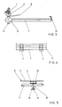
- Fig. 1 eine isometrische Darstellung zweier aufgestellter Gerüstrahmen mit einer schräg angeordneten Abdeckplatte;
- Fig. 2 eine Draufsicht auf die Ausführung nach Fig. 1 mit zusätzlich angeordneter Ausgleichsplatte;
- Fig. 3 einen Horizontalschnitt durch einen Gerüstrahmen mit einseitig angeordneter Gerüstkupplung, Muffe und Trägerrohr;
- Fig. 4 eine Stirnansicht mehrerer gestapelter Abdeckplatten und
- Fig. 5 einen Vertikalschnitt durch eine Anschlußstelle einer Abdeckplatte an das Trägerrohr.
- Zwischen zwei Gerüstrahmen 1 ist eine Abdeckplatte 2 aus wetterfestem und wasserundurchlässigem Material fest angeordnet. Diese Abdeckplatten 2 sind in sich steif ausgebildet, wobei auch die Möglichkeit besteht, in einem umlaufenden Rahmen eine den Anforderungen entsprechende Füllung einzulegen. Wie aus Fig. 4 erkennbar, sind die Längsseiten der Abdeckplatten 2 mit Aufkantungen 3 versehen, die leicht nach außen geneigt verlaufen und die über die Längsseite durchlaufen. Auf der Unterseite jeder Abdeckplatte 2 sind zwei parallel zu den Aufkantungen 3 verlaufende U-förmige Befestigungsschienen 4 mit ihrem Steg fest angeordnet. Die Flansche dieser Befestigungsschienen 4 sind rechtwinklig zueinander abgebogen, so daß zwischen den Stirnseiten der Abbiegungen ein Freiraum zur Einführung einer Auflagerplatte 12 gebildet ist. Die in Fig. 4 schematisch dargestellte Stapelung der Abdeckplatten 2 wird durch die leicht nach außen geneigt verlaufenden Aufkantungen 3 ermöglicht.
- An der äußeren Stütze des Gerüstrahmens 1 ist in einer Gerüstkupplung 5 eine verdrehbare Muffe 6 zur Aufnahme eines frei auskragenden Trägerrohrs 7 angeordnet, das den Zwischenraum zwischen der äußeren Stütze des Gerüstrahmens 1 und der Gebäudewand überbrückt und bis über das Dach geführt ist. Zur Erreichung des Verdrehens der Muffe 6 sind die Berührungsflächen zwischen der Gerüstkupplung 5 und der Muffe 6 als Rastgewinde 8 ausgebildet. In der gewählten Stellung der Muffe 6 wird das Rastgewinde 8 durch eine von der Innenseite der Gerüstkupplung 5 aus betätigbare Stellschraube 9 arretiert. Da vor dem Aufstellen der Gerüstrahmen 1 bzw. vor der Arretierung der Muffe 6 jeweils die für die Lage der Abdeckplatten 2 erforderliche Neigung feststeht, kann diese Neigung vor dem Anbringen der Gerüstkupplung 5 an die Stütze des Gerüstrahmens 1 eingestellt und arretiert werden.
- Da durch die Abdeckplatten 2, so wie aus Fig. 1 ersichtlich ist, der Raum zwischen den Gerüstrahmen 1 abgedeckt wird, ist zur Abdeckung des Zwischenraums zwischen den Gerüstrahmen 1 und der Gebäudewand, der im allgemeinen 30 cm beträgt, die Anordnung einer Ausgleichsplatte 11 erforderlich. Die Ausgleichsplatte 11 ragt über das Dach, damit der Spalt und damit die Außenseite der Gebäudewand gegen Witterungseinflüsse gesichert ist. Die Ausgleichsplatte 11 lagert ebenso wie die Abdeckplatte 2 auf den Trägerrohren 7, liegt also in einer Ebene mit den Abdeckplatten 2. Zur Herstellung einer Verbindung mit den Trägerrohren 7 besitzt die Ausgleichsplatte 11 auf ihrer Unterseite ebenfalls Befestigungsschienen 4. Zum Anschluß der Befestigungsschienen 4 der Abdeckplatte 2 und der Ausgleichsplatte 11 an das Trägerrohr 7 dient ein mit einer Auflagerplatte 12 und einer Flügelmutter 13 versehener Gewindestift 14, auf dem ein Auflagerhalter 16 geführt ist.
- Die Ausgleichsplatte 11 weist an beiden Stirnseiten Aussparungen 15 und 15′ auf, in denen die Stützen des Gerüstrahmens 1 geführt sind. Um die Ausgleichsplatte 11 den unterschiedlichen Dachneigungen anpassen zu können, sind die Aussparungen 15′ auf einer Stirnseite der Ausgleichsplatte 11 bedeutend länger als auf der anderen Stirnseite. Zweckmäßigerweise ist die längere Aussparung 15′ dreimal so lang wie die andere Aussparung 15. Um eine Überlappung an den Stirnseiten zu ermöglichen, verlaufen die Abdeckplatte 2 und die Ausgleichsplatte 11 in Längsrichtung konisch, so daß die schmalere Stirnseite in die breitere Stirnseite eingelegt werden kann. Am Ende des frei auskragenden Trägerrohrs 7 ist ein nach oben weisender Haken 10, siehe Fig. 3, angeordnet, der zur einseitigen Halterung der Ausgleichsplatte 11 dient. Hierzu wird die Ausgleichsplatte 11 lediglich unter diesen Haken 10 geschoben. Dieser Haken 10 ist zur stabilen Halterung der über das Dach reichenden Ausgleichsplatte 11 erforderlich, da im Dachbereich keine Befestigung an der Befestigungsschiene 4 möglich ist.
- Bei einer Variante verläuft das Trägerrohr 7 im Bereich der Auflagerung der Ausgleichsplatte 11 nach unten abgewinkelt, so daß die Ausgleichsplatte 11 gegenüber der Abdeckplatte 2 tiefer liegt. Bei in schräger Lage verlegten Platten 2 und 11 wird dadurch eine kontrollierte Wasserabführung ermöglicht.
-
- 1 Gerüstrahmen
- 2 Abdeckplatte
- 3 Aufkantungen
- 4 Befestigungsschiene
- 5 Gerüstkupplung
- 6 Muffe
- 7 Trägerrohr
- 8 Rastgewinde
- 9 Stellschraube
- 10 Haken
- 11 Ausgleichsplatte
- 12 Auflagerplatte
- 13 Flügelmutter
- 14 Gewindestift
- 15 Aussparung
- 15′ Aussparung
- 16 Auflagerhalter
Claims (29)
Priority Applications (1)
| Application Number | Priority Date | Filing Date | Title |
|---|---|---|---|
| AT89108355T ATE91744T1 (de) | 1988-05-13 | 1989-05-10 | Abdeckung fuer bau- und malergerueste. |
Applications Claiming Priority (2)
| Application Number | Priority Date | Filing Date | Title |
|---|---|---|---|
| DE3816320A DE3816320C1 (de) | 1988-05-13 | 1988-05-13 | |
| DE3816320 | 1988-05-13 |
Publications (3)
| Publication Number | Publication Date |
|---|---|
| EP0341678A2 true EP0341678A2 (de) | 1989-11-15 |
| EP0341678A3 EP0341678A3 (en) | 1990-03-28 |
| EP0341678B1 EP0341678B1 (de) | 1993-07-21 |
Family
ID=6354288
Family Applications (1)
| Application Number | Title | Priority Date | Filing Date |
|---|---|---|---|
| EP89108355A Expired - Lifetime EP0341678B1 (de) | 1988-05-13 | 1989-05-10 | Abdeckung für Bau- und Malergerüste |
Country Status (3)
| Country | Link |
|---|---|
| EP (1) | EP0341678B1 (de) |
| AT (1) | ATE91744T1 (de) |
| DE (1) | DE3816320C1 (de) |
Cited By (4)
| Publication number | Priority date | Publication date | Assignee | Title |
|---|---|---|---|---|
| GB2389622A (en) * | 2002-06-13 | 2003-12-17 | Mvs Services | Scaffolding system with brackets to retain protective panels |
| AU2003236467B1 (en) * | 2003-08-26 | 2004-01-22 | Atf Hire Group Pty Limited | A Void Platform and Method of Erecting Same |
| AU2004267122B2 (en) * | 2003-08-26 | 2007-02-01 | Atf Hire Group Pty Limited | A void platform and method of erecting same |
| WO2020148513A1 (en) * | 2019-01-15 | 2020-07-23 | Sky Lid Limited | Apparatus for providing a temporary weatherproof cover |
Family Cites Families (13)
| Publication number | Priority date | Publication date | Assignee | Title |
|---|---|---|---|---|
| FR1148151A (fr) * | 1956-04-18 | 1957-12-04 | Platelage métallique | |
| DE1852607U (de) * | 1962-02-26 | 1962-05-30 | Josef Hartung | Vorrichtung als provisorische arbeits- und lagerueberdachung. |
| CH535338A (fr) * | 1971-02-19 | 1973-03-31 | Barbey Alexis | Dispositif de couverture de chantier |
| FR2221949A5 (en) * | 1973-03-15 | 1974-10-11 | Aplibat | Scaffolding caisson-type platform - has sides which fit over poles, and base resting on tubular reinforcements |
| DE7514453U (de) * | 1975-05-06 | 1975-09-11 | Plettac Gmbh | Schutzdach |
| DD123367A1 (de) * | 1975-12-11 | 1976-12-12 | ||
| FR2351230A1 (fr) * | 1976-05-13 | 1977-12-09 | Outinord St Amand | Perfectionnements aux passerelles de coffrage |
| DE2637298A1 (de) * | 1976-08-19 | 1978-02-23 | Rupert Sonnauer | Wetterschutzvorrichtung fuer ein zerlegbares geruest |
| NL185947C (nl) * | 1978-08-03 | 1990-08-16 | Nicolon Nv | Steigerbekleding en steiger. |
| DE2909883A1 (de) * | 1979-03-14 | 1980-09-18 | Anton Rosendahl | Wetterschutzvorrichtung fuer bauarbeiter |
| GB2045307B (en) * | 1979-04-04 | 1983-03-16 | Jrm Construction Ltd | Building aid |
| DE8135977U1 (de) * | 1981-12-10 | 1983-03-31 | Müller & Baum GmbH & Co KG, 5768 Sundern | "tragkonstruktion fuer eine wetterverkleidung an einem baugeruest" |
| DE3609785C1 (de) * | 1986-03-22 | 1986-12-18 | Hans 1000 Berlin Herdzin | Verkleidung für Baugerüste |
-
1988
- 1988-05-13 DE DE3816320A patent/DE3816320C1/de not_active Expired
-
1989
- 1989-05-10 AT AT89108355T patent/ATE91744T1/de not_active IP Right Cessation
- 1989-05-10 EP EP89108355A patent/EP0341678B1/de not_active Expired - Lifetime
Cited By (4)
| Publication number | Priority date | Publication date | Assignee | Title |
|---|---|---|---|---|
| GB2389622A (en) * | 2002-06-13 | 2003-12-17 | Mvs Services | Scaffolding system with brackets to retain protective panels |
| AU2003236467B1 (en) * | 2003-08-26 | 2004-01-22 | Atf Hire Group Pty Limited | A Void Platform and Method of Erecting Same |
| AU2004267122B2 (en) * | 2003-08-26 | 2007-02-01 | Atf Hire Group Pty Limited | A void platform and method of erecting same |
| WO2020148513A1 (en) * | 2019-01-15 | 2020-07-23 | Sky Lid Limited | Apparatus for providing a temporary weatherproof cover |
Also Published As
| Publication number | Publication date |
|---|---|
| DE3816320C1 (de) | 1989-12-21 |
| EP0341678A3 (en) | 1990-03-28 |
| EP0341678B1 (de) | 1993-07-21 |
| ATE91744T1 (de) | 1993-08-15 |
Similar Documents
| Publication | Publication Date | Title |
|---|---|---|
| EP3712353A1 (de) | Halterung zum haltern eines geländerbestandteils an einem decken-schalungspaneel | |
| DE2123351C3 (de) | Schalungseinrichtung für eine wiederverwendbare Schalung einer Verbunddecke | |
| EP0108222A2 (de) | Traggestell | |
| DE2814095A1 (de) | Verbinder fuer zwei sich kreuzende schienen | |
| DE3108020A1 (de) | "schutzvorrichtung fuer metallgerueste" | |
| EP0341678A2 (de) | Abdeckung für Bau- und Malergerüste | |
| DE3122593C2 (de) | ||
| EP0877131A1 (de) | Befestigungsvorrichtung für ein Gerüst an einer Wand oder einer Attika | |
| DE3709441A1 (de) | Auf dem dach eines gedeckten gebaeudes abstuetzbares kamingeruest | |
| DE4114531A1 (de) | Arbeitsbuehne fuer waende oder schalungen | |
| DE4404042C1 (de) | Arbeitsgerüst für Bauwerke | |
| DE4318678A1 (de) | Gerüstabdeckung | |
| DE19951457B4 (de) | Abdeckung für Wände, zum Beispiel für Mauerwerk | |
| DE3213482C1 (de) | Ausschalhilfe | |
| DE19946060A1 (de) | Verfahren und Vorrichtung zur Erhöhung und/oder Sanierung von Masten | |
| DE3639129C2 (de) | ||
| EP0625619B1 (de) | Gerüstbühne | |
| DE8127001U1 (de) | Abschaleinrichtung fuer die halterung von schalbrettern | |
| DE2556970C2 (de) | Verbaueinheit zum Aussteifen der Wände von Baugräben, Rohrgräben oder dergleichen | |
| DE1116378B (de) | Konsolengeruest | |
| WO1993016246A1 (de) | Vorrichtung zur schalldämmung in räumen | |
| CH674870A5 (en) | Balustrade mounting on building site | |
| WO2025123065A1 (de) | Balkon, gebäude mit diesem balkon und verfahren zur anbringung dieses balkons | |
| DE3048043A1 (de) | Schalungsstuetze | |
| EP4411089A1 (de) | Sicherungsvorrichtung und system für arbeiten auf geneigten dächern |
Legal Events
| Date | Code | Title | Description |
|---|---|---|---|
| PUAI | Public reference made under article 153(3) epc to a published international application that has entered the european phase |
Free format text: ORIGINAL CODE: 0009012 |
|
| AK | Designated contracting states |
Kind code of ref document: A2 Designated state(s): AT BE CH FR GB LI LU NL SE |
|
| PUAL | Search report despatched |
Free format text: ORIGINAL CODE: 0009013 |
|
| AK | Designated contracting states |
Kind code of ref document: A3 Designated state(s): AT BE CH FR GB LI LU NL SE |
|
| 17P | Request for examination filed |
Effective date: 19900224 |
|
| 17Q | First examination report despatched |
Effective date: 19910717 |
|
| GRAA | (expected) grant |
Free format text: ORIGINAL CODE: 0009210 |
|
| AK | Designated contracting states |
Kind code of ref document: B1 Designated state(s): AT BE CH FR GB LI LU NL SE |
|
| REF | Corresponds to: |
Ref document number: 91744 Country of ref document: AT Date of ref document: 19930815 Kind code of ref document: T |
|
| GBT | Gb: translation of ep patent filed (gb section 77(6)(a)/1977) |
Effective date: 19930726 |
|
| ET | Fr: translation filed | ||
| PLBE | No opposition filed within time limit |
Free format text: ORIGINAL CODE: 0009261 |
|
| STAA | Information on the status of an ep patent application or granted ep patent |
Free format text: STATUS: NO OPPOSITION FILED WITHIN TIME LIMIT |
|
| 26N | No opposition filed | ||
| EPTA | Lu: last paid annual fee | ||
| EAL | Se: european patent in force in sweden |
Ref document number: 89108355.2 |
|
| PGFP | Annual fee paid to national office [announced via postgrant information from national office to epo] |
Ref country code: LU Payment date: 19950501 Year of fee payment: 7 |
|
| PGFP | Annual fee paid to national office [announced via postgrant information from national office to epo] |
Ref country code: GB Payment date: 19950505 Year of fee payment: 7 |
|
| PGFP | Annual fee paid to national office [announced via postgrant information from national office to epo] |
Ref country code: SE Payment date: 19950508 Year of fee payment: 7 |
|
| PGFP | Annual fee paid to national office [announced via postgrant information from national office to epo] |
Ref country code: AT Payment date: 19950522 Year of fee payment: 7 |
|
| PGFP | Annual fee paid to national office [announced via postgrant information from national office to epo] |
Ref country code: FR Payment date: 19950530 Year of fee payment: 7 |
|
| PGFP | Annual fee paid to national office [announced via postgrant information from national office to epo] |
Ref country code: NL Payment date: 19950531 Year of fee payment: 7 |
|
| PGFP | Annual fee paid to national office [announced via postgrant information from national office to epo] |
Ref country code: BE Payment date: 19950602 Year of fee payment: 7 |
|
| PGFP | Annual fee paid to national office [announced via postgrant information from national office to epo] |
Ref country code: CH Payment date: 19950613 Year of fee payment: 7 |
|
| PG25 | Lapsed in a contracting state [announced via postgrant information from national office to epo] |
Ref country code: LU Free format text: LAPSE BECAUSE OF NON-PAYMENT OF DUE FEES Effective date: 19960510 Ref country code: GB Effective date: 19960510 Ref country code: AT Effective date: 19960510 |
|
| PG25 | Lapsed in a contracting state [announced via postgrant information from national office to epo] |
Ref country code: SE Effective date: 19960511 |
|
| PG25 | Lapsed in a contracting state [announced via postgrant information from national office to epo] |
Ref country code: LI Effective date: 19960531 Ref country code: CH Effective date: 19960531 Ref country code: BE Effective date: 19960531 |
|
| BERE | Be: lapsed |
Owner name: EIKERMANN MANFRED Effective date: 19960531 |
|
| PG25 | Lapsed in a contracting state [announced via postgrant information from national office to epo] |
Ref country code: NL Effective date: 19961201 |
|
| GBPC | Gb: european patent ceased through non-payment of renewal fee |
Effective date: 19960510 |
|
| REG | Reference to a national code |
Ref country code: CH Ref legal event code: PL |
|
| PG25 | Lapsed in a contracting state [announced via postgrant information from national office to epo] |
Ref country code: FR Effective date: 19970131 |
|
| EUG | Se: european patent has lapsed |
Ref document number: 89108355.2 |
|
| NLV4 | Nl: lapsed or anulled due to non-payment of the annual fee |
Effective date: 19961201 |
|
| REG | Reference to a national code |
Ref country code: FR Ref legal event code: ST |