EP0341414B1 - Dispositif de protection pour râteau-faneurs avec outils de travail relevables - Google Patents
Dispositif de protection pour râteau-faneurs avec outils de travail relevables Download PDFInfo
- Publication number
- EP0341414B1 EP0341414B1 EP89105912A EP89105912A EP0341414B1 EP 0341414 B1 EP0341414 B1 EP 0341414B1 EP 89105912 A EP89105912 A EP 89105912A EP 89105912 A EP89105912 A EP 89105912A EP 0341414 B1 EP0341414 B1 EP 0341414B1
- Authority
- EP
- European Patent Office
- Prior art keywords
- linkage
- guard device
- machine
- pivots
- quadrilateral
- Prior art date
- Legal status (The legal status is an assumption and is not a legal conclusion. Google has not performed a legal analysis and makes no representation as to the accuracy of the status listed.)
- Expired - Lifetime
Links
- 230000001681 protective effect Effects 0.000 abstract description 22
- 230000005540 biological transmission Effects 0.000 description 2
- 230000008878 coupling Effects 0.000 description 2
- 238000010168 coupling process Methods 0.000 description 2
- 238000005859 coupling reaction Methods 0.000 description 2
- 230000006978 adaptation Effects 0.000 description 1
- 230000006835 compression Effects 0.000 description 1
- 238000007906 compression Methods 0.000 description 1
Images

Classifications
-
- A—HUMAN NECESSITIES
- A01—AGRICULTURE; FORESTRY; ANIMAL HUSBANDRY; HUNTING; TRAPPING; FISHING
- A01D—HARVESTING; MOWING
- A01D78/00—Haymakers with tines moving with respect to the machine
- A01D78/08—Haymakers with tines moving with respect to the machine with tine-carrying rotary heads or wheels
- A01D78/10—Haymakers with tines moving with respect to the machine with tine-carrying rotary heads or wheels the tines rotating about a substantially vertical axis
- A01D78/1007—Arrangements to facilitate transportation specially adapted therefor
- A01D78/1014—Folding frames
Definitions
- the invention relates to rotary hay machines with a protective device according to the preamble of claim 1.
- Rotary hay machines of this type have become known through a brochure from Kuhn SA Saverne with the designation "Giroheuer GF 6000 MH" and the issue date 11/87.
- the protective device can be folded up about a longitudinal axis which, viewed transversely to the direction of travel, lies on the machine frame at a distance from the pivot axis of the inner arm.
- the protective device In the vicinity of its free end, the protective device is connected to a linkage which in turn is connected to an outer, fold-up arm for the working tools.
- the linkage is coupled to the protective device via a slot guide, which among other things serves to allow the boom to move freely in the working position for ground adaptation without the protective device being moved as well.
- this coupling via a slot guide has the disadvantage that the protective device is only held loosely above its own weight in the horizontal position in the working position and can constantly deflect upwards when driving over uneven terrain, as a result of which noise is generated and great wear is caused.
- the feature of claim 2 aims to suppress the games in the joints of the four-bar linkage in the working position and thus to tension the protective device with the machine frame without play.
- This tension can, for. B. done in that the linkage is arranged transversely to the direction of travel and has a slight excess length relative to the stop for the lowest position of the protective device and bends somewhat in the lowest position, or that a compression spring is installed at a suitable location, for example.
- the linkage should run obliquely to the direction of travel. If, as described above, it also has a slight excess length, then in the working position the free ends of the support bracket for the protective device are spread elastically and thus serve as a spring for bracing the joints.
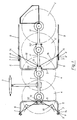
- a rotary hay machine has a machine frame (1) that runs on two wheels (2). It is connected to a tractor (not shown) via a three-point bracket (3). Working tools (4) are mounted on the underside of the machine frame (1).
- a support bracket (5) with free ends (6) is firmly connected to the machine frame (1). The free ends (6) have fixed stops (7).
- Rod-shaped protective devices (9) are arranged rotatably about axes of rotation (8).
- inner boom (11) and outer boom (11') are rotatably mounted. They each carry an impeller (2 ') and a working tool (4').
- the boom (11, 11 ') can be raised or lowered with hydraulic lifting cylinders (12).
- the rod-shaped protective devices (9) have an inward extension (9 '), which lies in the (lowered) working position from below against the stops (7) (Fig. 1 and 2, right half of the picture).
- the arms (11) have an articulated plate (13) and the rod-shaped protective devices (9) have an articulated plate (14).
- the link plates (13, 14) are connected to one another via a linkage (15).
- FIG. 3 the transmission chinematics of the four-bar linkage is shown schematically.
- the frame (S) is formed by the connecting line between a joint (10) and an axis of rotation (8), the crank (R) by the connecting line between a joint (10) and a joint plate (13), the rocker (r) the connecting line between an axis of rotation (8) and a hinge plate (14), while the handlebar (L) is formed by the linkage (15).
- the four-bar linkage (S, R, r, L) is designed so that the rod-shaped protective devices (9) are approximately vertical when the boom (11) is raised, while the rod-shaped protective devices (9) are approximately horizontal when the boom (11) is folded down its inward extension (9 ') presses against the stop (7) with prestress and thereby tensions all articulation points (8, 10, 14, 13).
Landscapes
- Life Sciences & Earth Sciences (AREA)
- Environmental Sciences (AREA)
- Agricultural Machines (AREA)
- Shovels (AREA)
- Soil Working Implements (AREA)
Claims (5)
- Râteau-faneur comprenant des outils de travail (4) montés de façon mobile sur des axes de pivotement (10) orientés dans la direction de la marche d'un bâti (1) de la machine et des bras (11) pouvant être relevés dans la position de transport, et un dispositif de protection (9, 9') qui est relié par une tringle (15) aux bras (11) de manière qu'à l'état relevé des bras (11) il soit sensiblement vertical, et qu'à l'état libre des bras (11) il soit sensiblement horizontal, la position la plus basse étant limitée par une butée fixe (7), caractérisé en ce que le bâti (1) de la machine, le bras (11), le dispositif de protection (9, 9') et la tringle (15) forment un quadrilatère articulé (S, R, r, L), dont la bielle (R) est disposée entre les articulations (10, 13) du bras (11), la structure de support (S) entre les articulations (8, 10) du bâti (1) de la machine, le bras (L) entre les articulations (13, 14) de la tringle (15), et le bras oscillant (r) entre les articulations (8, 14) du dispositif de protection (9, 9'), le bras oscillant (r) et la bielle (R), vus en direction transversale à la direction de la marche et dans la position de travail de la machine sont respectivement plus petits que le bras (L) et la structure (S), et dont, vues en direction en hauteur et dans la position de travail de la machine, les articulations (13, 14) de la tringle (15) sont disposées au-dessus des articulations (8, 10) du bâti (1) de la machine, et des parties de ce quadrilatère articulé (S, R, r, L) sont de constitution élastique.
- Râteau-faneur à dispositif de protection selon la revendication 1, caractérisé en ce que le quadrilatère articulé (S, R, r, L) est constitué de manière que le dispositif de protection (9, 9') à l'état abaissé des bras (11) s'applique élastiquement contre une butée fixe (7) du bâti (1) de la machine.
- Râteau-faneur à dispositif de protection selon les revendications 1 et 2, caractérisé en ce que la tringle (15) est agencée en oblique par rapport à la direction de la marche et est fixée de façon articulée d'une part au bras (11) et d'autre part au dispositif de protection (9).
- Râteau-faneur à dispositif de protection selon la revendication 3, caractérisé en ce que la tringle (15) est transversale à la direction de la marche.
- Râteau-faneur à dispositif de protection selon les revendications 1 à 4, caractérisé en ce que la bielle (R) du quadrilatère articulé (S, R, r, L) est plus longue que le bras oscillant (r) du quadrilatère articulé (S, R, r, L).
Priority Applications (1)
| Application Number | Priority Date | Filing Date | Title |
|---|---|---|---|
| AT89105912T ATE100271T1 (de) | 1988-05-11 | 1989-04-05 | Schutzvorrichtung fuer kreiselheumaschinen mit hochklappbaren arbeitswerkzeugen. |
Applications Claiming Priority (2)
| Application Number | Priority Date | Filing Date | Title |
|---|---|---|---|
| DE3816123A DE3816123A1 (de) | 1988-05-11 | 1988-05-11 | Schutzvorrichtung fuer kreiselheumaschinen mit hochklappbaren arbeitswerkzeugen |
| DE3816123 | 1988-05-11 |
Publications (2)
| Publication Number | Publication Date |
|---|---|
| EP0341414A1 EP0341414A1 (fr) | 1989-11-15 |
| EP0341414B1 true EP0341414B1 (fr) | 1994-01-19 |
Family
ID=6354178
Family Applications (1)
| Application Number | Title | Priority Date | Filing Date |
|---|---|---|---|
| EP89105912A Expired - Lifetime EP0341414B1 (fr) | 1988-05-11 | 1989-04-05 | Dispositif de protection pour râteau-faneurs avec outils de travail relevables |
Country Status (3)
| Country | Link |
|---|---|
| EP (1) | EP0341414B1 (fr) |
| AT (1) | ATE100271T1 (fr) |
| DE (2) | DE3816123A1 (fr) |
Families Citing this family (3)
| Publication number | Priority date | Publication date | Assignee | Title |
|---|---|---|---|---|
| FR2661312B1 (fr) * | 1990-04-27 | 1992-07-17 | Kuhn Sa | Machine de fenaison avec plusieurs rotors. |
| DE4111591A1 (de) * | 1990-06-19 | 1992-01-02 | Poettinger Alois Landmasch | Heuwerbungsmaschine |
| DE19541654A1 (de) * | 1995-11-08 | 1997-05-15 | Claas Saulgau Gmbh | Anordnung von Schutzbügeln für Vielkreiselheuwender |
Family Cites Families (5)
| Publication number | Priority date | Publication date | Assignee | Title |
|---|---|---|---|---|
| DD156635A1 (de) * | 1981-03-02 | 1982-09-08 | Rainer Gutsch | Verfahren zur trennung von gestaltabweichungen technischer oberflaechen |
| DE3603014A1 (de) * | 1986-01-31 | 1987-08-06 | Kloeckner Humboldt Deutz Ag | Kreiselzettwender |
| DE8625784U1 (de) * | 1986-09-26 | 1987-03-05 | Klöckner-Humboldt-Deutz AG Zweigniederlassung Fahr, 7702 Gottmadingen | Kreiselheuwerbungsmaschine |
| DE8709233U1 (de) * | 1987-03-20 | 1987-12-10 | KHD Agrartechnik GmbH, 7702 Gottmadingen | Kreiselheuwerbungsmaschine |
| DE8712165U1 (de) * | 1987-09-08 | 1987-10-29 | Fella-Werke Gmbh, 8501 Feucht | Schutzvorrichtung für Heuwerbungsmaschinen |
-
1988
- 1988-05-11 DE DE3816123A patent/DE3816123A1/de not_active Ceased
-
1989
- 1989-04-05 AT AT89105912T patent/ATE100271T1/de not_active IP Right Cessation
- 1989-04-05 DE DE89105912T patent/DE58906727D1/de not_active Expired - Fee Related
- 1989-04-05 EP EP89105912A patent/EP0341414B1/fr not_active Expired - Lifetime
Also Published As
| Publication number | Publication date |
|---|---|
| DE3816123A1 (de) | 1989-11-23 |
| DE58906727D1 (de) | 1994-03-03 |
| ATE100271T1 (de) | 1994-02-15 |
| EP0341414A1 (fr) | 1989-11-15 |
Similar Documents
| Publication | Publication Date | Title |
|---|---|---|
| DE69705807T2 (de) | Heuwerbungsmaschine | |
| DE4007735C2 (de) | Landwirtschaftliche Arbeitsmaschine zum Frontanbau an einen Schlepper | |
| EP0484794B1 (fr) | Machine de fenaison | |
| EP0391093B1 (fr) | Machine agricole | |
| EP0456900A2 (fr) | Machine agricole | |
| EP0381970B1 (fr) | Machine de fenaison | |
| EP1593294A1 (fr) | Dispositif d'accouplement pour faucheuse | |
| EP0429934A1 (fr) | Epandeur agricole | |
| EP0341414B1 (fr) | Dispositif de protection pour râteau-faneurs avec outils de travail relevables | |
| EP0415301B1 (fr) | Machine de fenaison | |
| DE3133713C2 (de) | Vorrichtung zur Befestigung von Arbeitsgeräten an Fahrzeugen | |
| DE2630493A1 (de) | An die dreipunktaufhaengung eines schleppers anschliessbarer kreiselmaeher | |
| EP0914761A1 (fr) | Suspension pour unités de travail des deux cotés d'un véhicule de support | |
| DE202011107679U1 (de) | Heuwerbungsmaschine | |
| EP0394830A1 (fr) | Machine agricole, en particulier faucheuse, destinée à être montée sur un tracteur | |
| EP0571794B1 (fr) | Machine à travaille agricole, notamment faneuse rotatoire | |
| DE4122072C2 (de) | Fahrwerk für Kreiselheumaschinen, wie Kreiselschwader | |
| DE1782942B2 (de) | Einrichtung zum Befestigen eines landwirtschaftlichen Gerätes an der genormten Dreipunktkupplung eines Schleppers | |
| DE2945062C2 (de) | Bodenbearbeitungsmaschine | |
| EP1829444B1 (fr) | Andaineuse rotative | |
| EP0503233B1 (fr) | Faucheuse rotative | |
| DE2206176C3 (de) | Tellerbesenaufhängung an einer Straßenkehrmaschine | |
| DE4103011C2 (de) | Mäh- oder Heumaschine | |
| DE3835366B4 (de) | Vorrichtung zur Bodenanpassung der Arbeitswerkzeuge von Heumaschinen | |
| EP1186233A2 (fr) | Dispositif de guidage d'une rampe d'épandage |
Legal Events
| Date | Code | Title | Description |
|---|---|---|---|
| PUAI | Public reference made under article 153(3) epc to a published international application that has entered the european phase |
Free format text: ORIGINAL CODE: 0009012 |
|
| 17P | Request for examination filed |
Effective date: 19890823 |
|
| AK | Designated contracting states |
Kind code of ref document: A1 Designated state(s): AT CH DE FR IT LI NL SE |
|
| 17Q | First examination report despatched |
Effective date: 19920703 |
|
| GRAA | (expected) grant |
Free format text: ORIGINAL CODE: 0009210 |
|
| ITF | It: translation for a ep patent filed | ||
| AK | Designated contracting states |
Kind code of ref document: B1 Designated state(s): AT CH DE FR IT LI NL SE |
|
| REF | Corresponds to: |
Ref document number: 100271 Country of ref document: AT Date of ref document: 19940215 Kind code of ref document: T |
|
| REF | Corresponds to: |
Ref document number: 58906727 Country of ref document: DE Date of ref document: 19940303 |
|
| ET | Fr: translation filed | ||
| PLBE | No opposition filed within time limit |
Free format text: ORIGINAL CODE: 0009261 |
|
| STAA | Information on the status of an ep patent application or granted ep patent |
Free format text: STATUS: NO OPPOSITION FILED WITHIN TIME LIMIT |
|
| 26N | No opposition filed | ||
| EAL | Se: european patent in force in sweden |
Ref document number: 89105912.3 |
|
| PGFP | Annual fee paid to national office [announced via postgrant information from national office to epo] |
Ref country code: DE Payment date: 20011002 Year of fee payment: 14 |
|
| PGFP | Annual fee paid to national office [announced via postgrant information from national office to epo] |
Ref country code: FR Payment date: 20020417 Year of fee payment: 14 |
|
| PGFP | Annual fee paid to national office [announced via postgrant information from national office to epo] |
Ref country code: NL Payment date: 20020422 Year of fee payment: 14 Ref country code: CH Payment date: 20020422 Year of fee payment: 14 Ref country code: AT Payment date: 20020422 Year of fee payment: 14 |
|
| PGFP | Annual fee paid to national office [announced via postgrant information from national office to epo] |
Ref country code: SE Payment date: 20020424 Year of fee payment: 14 |
|
| PG25 | Lapsed in a contracting state [announced via postgrant information from national office to epo] |
Ref country code: AT Free format text: LAPSE BECAUSE OF NON-PAYMENT OF DUE FEES Effective date: 20030405 |
|
| PG25 | Lapsed in a contracting state [announced via postgrant information from national office to epo] |
Ref country code: SE Free format text: LAPSE BECAUSE OF NON-PAYMENT OF DUE FEES Effective date: 20030406 |
|
| PG25 | Lapsed in a contracting state [announced via postgrant information from national office to epo] |
Ref country code: LI Free format text: LAPSE BECAUSE OF NON-PAYMENT OF DUE FEES Effective date: 20030430 Ref country code: CH Free format text: LAPSE BECAUSE OF NON-PAYMENT OF DUE FEES Effective date: 20030430 |
|
| PG25 | Lapsed in a contracting state [announced via postgrant information from national office to epo] |
Ref country code: NL Free format text: LAPSE BECAUSE OF NON-PAYMENT OF DUE FEES Effective date: 20031101 Ref country code: DE Free format text: LAPSE BECAUSE OF NON-PAYMENT OF DUE FEES Effective date: 20031101 |
|
| NLV4 | Nl: lapsed or anulled due to non-payment of the annual fee |
Effective date: 20031101 |
|
| EUG | Se: european patent has lapsed | ||
| REG | Reference to a national code |
Ref country code: CH Ref legal event code: PL |
|
| PG25 | Lapsed in a contracting state [announced via postgrant information from national office to epo] |
Ref country code: FR Free format text: LAPSE BECAUSE OF NON-PAYMENT OF DUE FEES Effective date: 20031231 |
|
| REG | Reference to a national code |
Ref country code: FR Ref legal event code: ST |
|
| PG25 | Lapsed in a contracting state [announced via postgrant information from national office to epo] |
Ref country code: IT Free format text: LAPSE BECAUSE OF NON-PAYMENT OF DUE FEES Effective date: 20050405 |