EP0341414B1 - Schutzvorrichtung für Kreiselheumaschinen mit hochklappbaren Arbeitswerkzeugen - Google Patents
Schutzvorrichtung für Kreiselheumaschinen mit hochklappbaren Arbeitswerkzeugen Download PDFInfo
- Publication number
- EP0341414B1 EP0341414B1 EP89105912A EP89105912A EP0341414B1 EP 0341414 B1 EP0341414 B1 EP 0341414B1 EP 89105912 A EP89105912 A EP 89105912A EP 89105912 A EP89105912 A EP 89105912A EP 0341414 B1 EP0341414 B1 EP 0341414B1
- Authority
- EP
- European Patent Office
- Prior art keywords
- linkage
- guard device
- machine
- pivots
- quadrilateral
- Prior art date
- Legal status (The legal status is an assumption and is not a legal conclusion. Google has not performed a legal analysis and makes no representation as to the accuracy of the status listed.)
- Expired - Lifetime
Links
- 230000001681 protective effect Effects 0.000 abstract description 22
- 230000005540 biological transmission Effects 0.000 description 2
- 230000008878 coupling Effects 0.000 description 2
- 238000010168 coupling process Methods 0.000 description 2
- 238000005859 coupling reaction Methods 0.000 description 2
- 230000006978 adaptation Effects 0.000 description 1
- 230000006835 compression Effects 0.000 description 1
- 238000007906 compression Methods 0.000 description 1
Images

Classifications
-
- A—HUMAN NECESSITIES
- A01—AGRICULTURE; FORESTRY; ANIMAL HUSBANDRY; HUNTING; TRAPPING; FISHING
- A01D—HARVESTING; MOWING
- A01D78/00—Haymakers with tines moving with respect to the machine
- A01D78/08—Haymakers with tines moving with respect to the machine with tine-carrying rotary heads or wheels
- A01D78/10—Haymakers with tines moving with respect to the machine with tine-carrying rotary heads or wheels the tines rotating about a substantially vertical axis
- A01D78/1007—Arrangements to facilitate transportation specially adapted therefor
- A01D78/1014—Folding frames
Definitions
- the invention relates to rotary hay machines with a protective device according to the preamble of claim 1.
- Rotary hay machines of this type have become known through a brochure from Kuhn SA Saverne with the designation "Giroheuer GF 6000 MH" and the issue date 11/87.
- the protective device can be folded up about a longitudinal axis which, viewed transversely to the direction of travel, lies on the machine frame at a distance from the pivot axis of the inner arm.
- the protective device In the vicinity of its free end, the protective device is connected to a linkage which in turn is connected to an outer, fold-up arm for the working tools.
- the linkage is coupled to the protective device via a slot guide, which among other things serves to allow the boom to move freely in the working position for ground adaptation without the protective device being moved as well.
- this coupling via a slot guide has the disadvantage that the protective device is only held loosely above its own weight in the horizontal position in the working position and can constantly deflect upwards when driving over uneven terrain, as a result of which noise is generated and great wear is caused.
- the feature of claim 2 aims to suppress the games in the joints of the four-bar linkage in the working position and thus to tension the protective device with the machine frame without play.
- This tension can, for. B. done in that the linkage is arranged transversely to the direction of travel and has a slight excess length relative to the stop for the lowest position of the protective device and bends somewhat in the lowest position, or that a compression spring is installed at a suitable location, for example.
- the linkage should run obliquely to the direction of travel. If, as described above, it also has a slight excess length, then in the working position the free ends of the support bracket for the protective device are spread elastically and thus serve as a spring for bracing the joints.
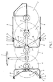
- a rotary hay machine has a machine frame (1) that runs on two wheels (2). It is connected to a tractor (not shown) via a three-point bracket (3). Working tools (4) are mounted on the underside of the machine frame (1).
- a support bracket (5) with free ends (6) is firmly connected to the machine frame (1). The free ends (6) have fixed stops (7).
- Rod-shaped protective devices (9) are arranged rotatably about axes of rotation (8).
- inner boom (11) and outer boom (11') are rotatably mounted. They each carry an impeller (2 ') and a working tool (4').
- the boom (11, 11 ') can be raised or lowered with hydraulic lifting cylinders (12).
- the rod-shaped protective devices (9) have an inward extension (9 '), which lies in the (lowered) working position from below against the stops (7) (Fig. 1 and 2, right half of the picture).
- the arms (11) have an articulated plate (13) and the rod-shaped protective devices (9) have an articulated plate (14).
- the link plates (13, 14) are connected to one another via a linkage (15).
- FIG. 3 the transmission chinematics of the four-bar linkage is shown schematically.
- the frame (S) is formed by the connecting line between a joint (10) and an axis of rotation (8), the crank (R) by the connecting line between a joint (10) and a joint plate (13), the rocker (r) the connecting line between an axis of rotation (8) and a hinge plate (14), while the handlebar (L) is formed by the linkage (15).
- the four-bar linkage (S, R, r, L) is designed so that the rod-shaped protective devices (9) are approximately vertical when the boom (11) is raised, while the rod-shaped protective devices (9) are approximately horizontal when the boom (11) is folded down its inward extension (9 ') presses against the stop (7) with prestress and thereby tensions all articulation points (8, 10, 14, 13).
Landscapes
- Life Sciences & Earth Sciences (AREA)
- Environmental Sciences (AREA)
- Agricultural Machines (AREA)
- Soil Working Implements (AREA)
- Shovels (AREA)
Description
- Die Erfindung bezieht sich auf Kreiselheumaschinen mit einer Schutzvorrichtung nach dem Oberbegriff des Anspruches 1.
- Kreiselheumaschinen dieser Gattung sind durch einen Prospekt der Firma Kuhn SA Saverne mit der Bezeichnung "Giroheuer GF 6000 MH" und dem Ausgabedatum 11/87 bekanntgeworden. Die Schutzvorrichtung ist bei dieser Maschine um eine Längsachse hochklappbar, die quer zur Fahrtrichtung gesehen mit Abstand von der Schwenkachse des inneren Auslegers am Maschinenrahmen liegt. In der Nähe ihres freien Endes ist die Schutzvorrichtung mit einem Gestänge verbunden, das seinerseits in Verbindung mit einem äußeren hochklappbaren Ausleger für die Arbeitswerkzeuge steht. Das Gestänge ist mit der Schutzvorrichtung über eine Schlitzführung gekoppelt, die unter anderem dazu dient, in der Arbeitsstellung eine freie Beweglichkeit der Ausleger zur Bodenanpassung zuzulassen, ohne daß die Schutzvorrichtung mitgewegt wird. Diese Koppelung über eine Schlitzführung hat aber den Nachteil, daß die Schutzvorrichtung in Arbeitsstellung nur lose über ihr Eigengewicht in Horizontallage gehalten wird und beim Überfahren von unebenem Gelände ständig nach oben ausschlagen kann, wodurch Geräusche erzeugt und großer Verschleiß bewirkt wird.
- Dieser Nachteil soll durch die Merkmale des kennzeichnenden Teiles des Anspruchs 1 behoben werden. Die freie Beweglichkeit der Schutzvorrichtung in der Arbeitsstellung wird dadurch unterbunden, daß der Maschinenrahmen, der Ausleger, die Schutzvorrichtung und das Gestänge ein Gelenkviereck bilden, das so gestaltet ist, daß für die Koppelung des Gestänges an der Schutzvorrichtung bzw. am Ausleger eine Schlitzführung entfallen kann, die Abstandsveränderungen der Schwenkachsen beim Schwenken der Ausleger mit der Schutzvorrichtung ausgleicht. Dadurch ist auch gewährleistet, daß sowohl in der Transportstellung, als auch in der Arbeitsstellung und in allen Zwischenstellungen eine eindeutige Zuordnung von Auslegern und Schutzvorrichtungen besteht.
- Das Merkmal des Anspruches 2 bezweckt, in der Arbeitsstellung auch noch die Spiele in den Gelenken des Gelenkvierecks zu unterdrücken und so die Schutzvorrichtung mit dem Maschinenrahmen spielfrei zu verspannen.
- Diese Verspannung kann z. B. dadurch erfolgen, daß das Gestänge quer zur Fahrtrichtung angeordnet ist und relativ zu dem Anschlag für die Tiefstlage der Schutzvorrichtung eine geringe Überlänge hat und sich in der Tiefstlage etwas durchbiegt, oder daß an geeigneter Stelle z.B. eine Druckfeder eingebaut ist.
- Nach einem anderen Merkmal der Erfindung soll das Gestänge schräg zur Fahrtrichtung verlaufen. Wenn es, wie oben geschildert, ebenfalls eine gerine Überlänge besitzt, dann werden in der Arbeitsstellung die freien Enden des Tragbügels für die Schutzvorrichtung elastisch aufgespreizt und dienen dadurch als Feder zur Verspannung der Gelenke.
- Ein weiteres Merkmal der Erfindung wird mit Anspruch 6 offenbart.
- Die Erfindung wird anhand von drei Abbildungen beispielsweise erläutert.
- Fig. 1 zeigt eine Schutzvorrichtung an einer Kreiselheumaschine in Ansicht von oben,
- Fig. 2 zeigt den gleichen Gegenstand von hinten und
- Fig. 3 eine schematische Darstellung der Getriebekinnematik.
- Eine Kreiselheumaschine hat einen Maschinenrahmen (1), der auf zwei Laufrädern (2) läuft. Er wird über einen Dreipunktbock (3) mit einem nicht dargestellten Schlepper verbunden. An der Unterseite des Maschinenrahmens (1) sind Arbeitswerkzeuge (4) gelagert. Mit dem Maschinenrahmen (1) ist ein Tragbügel (5) mit freien Enden (6) fest verbunden. Die freien Enden (6) besitzen feste Anschläge (7). Um Drehachsen (8) sind stangenförmige Schutzvorrichtungen (9) drehbar angeordnet.
- An Gelenken (10, 10′) sind innere Ausleger (11) und äußere Ausleger (11′) drehbar gelagert. Sie tragen je ein Laufrad (2′) und ein Arbeitswerkzeug (4′). Die Ausleger (11, 11′) können mit hydraulischen Hubzylindern (12) hochgehoben oder abgesenkt werden.
- Die stangenförmigen Schutzvorrichtungen (9) haben einen nach innen gerichteten Fortsatz (9′), der sich in der (abgesenkten) Arbeitsstellung von unten gegen die Anschläge (7) anlegt (Fig. 1 und 2, rechte Bildhälfte). Die Ausleger (11) besitzen eine Gelenklasche (13) und die stangenförmigen Schutzvorrichtungen (9) eine Gelenklasche (14). Die Gelenklaschen (13, 14) sind über ein Gestänge (15) miteinander verbunden.
- In Fig. 3 ist die Getriebekinnematik des Gelenkvierecks schematisch dargestellt. Das Gestell (S) wird von der Verbindungslinie zwischen einem Gelenk (10) und einer Drehachse (8) gebildet, die Kurbel (R) durch die Verbindungslinie zwischen einem Gelenk (10) und einer Gelenklasche (13), die Schwinge (r) durch die Verbindungslinie zwischen einer Drehachse (8) und einer Gelenklasche (14), während der Lenker (L) durch das Gestänge (15) gebildet wird.
- Das Gelenkviereck (S, R, r, L) ist so ausgelegt, daß die stabförmigen Schutzvorrichtungen (9) bei hochgeklapptem Ausleger (11) etwa senkrecht stehen, während bei abgeklapptem Ausleger (11) die stabförmigen Schutzvorrichtungen (9) etwa waagrecht liegen und ihr nach innen gerichteter Fortsatz (9′) mit Vorspannung gegen den Anschlag (7) drückt und dadurch alle Gelenkstellen (8, 10, 14, 13) verspannt.
Claims (5)
- Kreiselheumaschine mit Arbeitswerkzeugen (4) an um in Fahrtrichtung liegende Schwenkachsen (10) an einem Maschinenrahmen (1) beweglich gelagerten und für eine Transportstellung hochklappbaren Auslegern (11) und mit einer Schutzvorrichtung (9, 9'), die über ein Gestänge (15) mit den Auslegern (11) so verbunden ist, daß sie in hochgeklapptem Zustand der Ausleger (11) etwa senkrecht steht, und in abgelassenem Zustand der Ausleger (11) etwa waagrecht liegt, wobei die Tiefstlage durch einen festen Anschlag (7) begrenzt ist, dadurch gekennzeichnet, daß der Maschinenrahmen (1), der Ausleger (11), die Schutzvorrichtung (9, 9') und das Gestänge (15) ein Gelenkviereck (S, R, r, L) bilden, wovon die Kurbel (R) zwischen den Gelenken (10, 13) am Ausleger (11), das Gestell (S) zwischen den Gelenken (8, 10) am Maschinenrahmen (1), der Lenker (L) zwischen den Gelenken (13, 14) am Gestänge (15) und die Schwinge (r) zwischen den Gelenken (8, 14) an der Schutzvorrichtung (9, 9') liegt, wobei die Schwinge (r) und die Kurbel (R), quer zur Fahrtrichtung gesehen in Arbeitsstellung der Maschine, jeweils kleiner sind als der Lenker (L) und das Gestell (S) und wovon, in Höhenrichtung gesehen in Arbeitsstellung der Maschine, die Gelenke (13, 14) am Gestänge (15) über den Gelenken (8, 10) am Maschinenrahmen (1) liegen, und daß Teile dieses Gelenkviereckes (S, R, r, L) elastisch ausgestaltet sind.
- Kreiselheumaschine mit Schutzvorrichtung nach Anspruch 1, dadurch gekennzeichnet, daß das Gelenkviereck (S, R, r, L) so ausgebildet ist, daß die Schutzvorrichtung (9,9') in abgelassenem Zustand der Ausleger (11) gegen einen festen Anschlag (7) am Maschinenrahmen (1) elastisch angedrückt wird.
- Kreiselheumaschine mit Schutzvorrichtung nach den Ansprüchen 1 und 2, dadurch gekennzeichnet, daß das Gestänge (15) schräg zur Fahrtrichtung verläuft und einerseits an dem Ausleger (11) und andererseits an der Schutzvorrichtung (9) gelenkig befestigt ist.
- Kreiselheumaschine mit Schutzvorrichtung nach Anspruch 3, dadurch gekennzeichnet, daß das Gestänge (15) quer zur Fahrtrichtung liegt.
- Kreiselheumaschine mit Schutzvorrichtung nach den Ansprüchen 1 bis 4, dadurch gekennzeichnet, daß die Kurbel (R) des Gelenkviereckes (S,R, r, L) länger als die Schwinge (r) des Gelenkviereckes (S, R, r, L) ist.
Priority Applications (1)
| Application Number | Priority Date | Filing Date | Title |
|---|---|---|---|
| AT89105912T ATE100271T1 (de) | 1988-05-11 | 1989-04-05 | Schutzvorrichtung fuer kreiselheumaschinen mit hochklappbaren arbeitswerkzeugen. |
Applications Claiming Priority (2)
| Application Number | Priority Date | Filing Date | Title |
|---|---|---|---|
| DE3816123 | 1988-05-11 | ||
| DE3816123A DE3816123A1 (de) | 1988-05-11 | 1988-05-11 | Schutzvorrichtung fuer kreiselheumaschinen mit hochklappbaren arbeitswerkzeugen |
Publications (2)
| Publication Number | Publication Date |
|---|---|
| EP0341414A1 EP0341414A1 (de) | 1989-11-15 |
| EP0341414B1 true EP0341414B1 (de) | 1994-01-19 |
Family
ID=6354178
Family Applications (1)
| Application Number | Title | Priority Date | Filing Date |
|---|---|---|---|
| EP89105912A Expired - Lifetime EP0341414B1 (de) | 1988-05-11 | 1989-04-05 | Schutzvorrichtung für Kreiselheumaschinen mit hochklappbaren Arbeitswerkzeugen |
Country Status (3)
| Country | Link |
|---|---|
| EP (1) | EP0341414B1 (de) |
| AT (1) | ATE100271T1 (de) |
| DE (2) | DE3816123A1 (de) |
Families Citing this family (3)
| Publication number | Priority date | Publication date | Assignee | Title |
|---|---|---|---|---|
| FR2661312B1 (fr) * | 1990-04-27 | 1992-07-17 | Kuhn Sa | Machine de fenaison avec plusieurs rotors. |
| DE4111591A1 (de) * | 1990-06-19 | 1992-01-02 | Poettinger Alois Landmasch | Heuwerbungsmaschine |
| DE19541654A1 (de) * | 1995-11-08 | 1997-05-15 | Claas Saulgau Gmbh | Anordnung von Schutzbügeln für Vielkreiselheuwender |
Family Cites Families (5)
| Publication number | Priority date | Publication date | Assignee | Title |
|---|---|---|---|---|
| DD156635A1 (de) * | 1981-03-02 | 1982-09-08 | Rainer Gutsch | Verfahren zur trennung von gestaltabweichungen technischer oberflaechen |
| DE3603014A1 (de) * | 1986-01-31 | 1987-08-06 | Kloeckner Humboldt Deutz Ag | Kreiselzettwender |
| DE8625784U1 (de) * | 1986-09-26 | 1987-03-05 | Klöckner-Humboldt-Deutz AG Zweigniederlassung Fahr, 7702 Gottmadingen | Kreiselheuwerbungsmaschine |
| DE8709233U1 (de) * | 1987-03-20 | 1987-12-10 | KHD Agrartechnik GmbH, 7702 Gottmadingen | Kreiselheuwerbungsmaschine |
| DE8712165U1 (de) * | 1987-09-08 | 1987-10-29 | Fella-Werke Gmbh, 8501 Feucht | Schutzvorrichtung für Heuwerbungsmaschinen |
-
1988
- 1988-05-11 DE DE3816123A patent/DE3816123A1/de not_active Ceased
-
1989
- 1989-04-05 EP EP89105912A patent/EP0341414B1/de not_active Expired - Lifetime
- 1989-04-05 AT AT89105912T patent/ATE100271T1/de not_active IP Right Cessation
- 1989-04-05 DE DE89105912T patent/DE58906727D1/de not_active Expired - Fee Related
Also Published As
| Publication number | Publication date |
|---|---|
| DE3816123A1 (de) | 1989-11-23 |
| ATE100271T1 (de) | 1994-02-15 |
| EP0341414A1 (de) | 1989-11-15 |
| DE58906727D1 (de) | 1994-03-03 |
Similar Documents
| Publication | Publication Date | Title |
|---|---|---|
| DE69705807T2 (de) | Heuwerbungsmaschine | |
| DE4007735C2 (de) | Landwirtschaftliche Arbeitsmaschine zum Frontanbau an einen Schlepper | |
| EP0484794B1 (de) | Heuwerbungsmaschine | |
| EP0391093B1 (de) | Landwirtschaftliche Arbeitsmaschine | |
| DE9213091U1 (de) | Kreiselegge | |
| EP0456900A2 (de) | Landwirtschaftliche Maschine | |
| EP1593294A1 (de) | Aufhängungsvorrichtung für ein Mähwerk | |
| EP0381970A2 (de) | Kreiselheumaschinen | |
| EP0429934A1 (de) | Landwirtschaftliche Verteilmaschine | |
| EP0415301B1 (de) | Heuwerbungsmaschine | |
| EP0914761B1 (de) | Trägerfahrzeug mit einer Aufhängung für beidseitig an diesem angebrachte Arbeitsaggregate | |
| DE3133713C2 (de) | Vorrichtung zur Befestigung von Arbeitsgeräten an Fahrzeugen | |
| DE2630493A1 (de) | An die dreipunktaufhaengung eines schleppers anschliessbarer kreiselmaeher | |
| EP0341414A1 (de) | Schutzvorrichtung für Kreiselheumaschinen mit hochklappbaren Arbeitswerkzeugen | |
| EP0394830A1 (de) | Landwirtschafliches Anbaugerät insbesondere Kreiselmähwerk | |
| EP0571794B1 (de) | Landwirtschaftliche Arbeitsmaschine, besonders Kreiselheuwender | |
| DE4122072C2 (de) | Fahrwerk für Kreiselheumaschinen, wie Kreiselschwader | |
| DE1782942B2 (de) | Einrichtung zum Befestigen eines landwirtschaftlichen Gerätes an der genormten Dreipunktkupplung eines Schleppers | |
| DE2945062C2 (de) | Bodenbearbeitungsmaschine | |
| EP1829444B1 (de) | Kreiselschwader | |
| EP0503233B1 (de) | Kreiselmähwerk | |
| EP0772968B1 (de) | Anordnung von Schutzbügeln für Vielkreiselheuwender | |
| DE2206176C3 (de) | Tellerbesenaufhängung an einer Straßenkehrmaschine | |
| DE4103011C2 (de) | Mäh- oder Heumaschine | |
| DE3835366B4 (de) | Vorrichtung zur Bodenanpassung der Arbeitswerkzeuge von Heumaschinen |
Legal Events
| Date | Code | Title | Description |
|---|---|---|---|
| PUAI | Public reference made under article 153(3) epc to a published international application that has entered the european phase |
Free format text: ORIGINAL CODE: 0009012 |
|
| 17P | Request for examination filed |
Effective date: 19890823 |
|
| AK | Designated contracting states |
Kind code of ref document: A1 Designated state(s): AT CH DE FR IT LI NL SE |
|
| 17Q | First examination report despatched |
Effective date: 19920703 |
|
| GRAA | (expected) grant |
Free format text: ORIGINAL CODE: 0009210 |
|
| ITF | It: translation for a ep patent filed | ||
| AK | Designated contracting states |
Kind code of ref document: B1 Designated state(s): AT CH DE FR IT LI NL SE |
|
| REF | Corresponds to: |
Ref document number: 100271 Country of ref document: AT Date of ref document: 19940215 Kind code of ref document: T |
|
| REF | Corresponds to: |
Ref document number: 58906727 Country of ref document: DE Date of ref document: 19940303 |
|
| ET | Fr: translation filed | ||
| PLBE | No opposition filed within time limit |
Free format text: ORIGINAL CODE: 0009261 |
|
| STAA | Information on the status of an ep patent application or granted ep patent |
Free format text: STATUS: NO OPPOSITION FILED WITHIN TIME LIMIT |
|
| 26N | No opposition filed | ||
| EAL | Se: european patent in force in sweden |
Ref document number: 89105912.3 |
|
| PGFP | Annual fee paid to national office [announced via postgrant information from national office to epo] |
Ref country code: DE Payment date: 20011002 Year of fee payment: 14 |
|
| PGFP | Annual fee paid to national office [announced via postgrant information from national office to epo] |
Ref country code: FR Payment date: 20020417 Year of fee payment: 14 |
|
| PGFP | Annual fee paid to national office [announced via postgrant information from national office to epo] |
Ref country code: NL Payment date: 20020422 Year of fee payment: 14 Ref country code: CH Payment date: 20020422 Year of fee payment: 14 Ref country code: AT Payment date: 20020422 Year of fee payment: 14 |
|
| PGFP | Annual fee paid to national office [announced via postgrant information from national office to epo] |
Ref country code: SE Payment date: 20020424 Year of fee payment: 14 |
|
| PG25 | Lapsed in a contracting state [announced via postgrant information from national office to epo] |
Ref country code: AT Free format text: LAPSE BECAUSE OF NON-PAYMENT OF DUE FEES Effective date: 20030405 |
|
| PG25 | Lapsed in a contracting state [announced via postgrant information from national office to epo] |
Ref country code: SE Free format text: LAPSE BECAUSE OF NON-PAYMENT OF DUE FEES Effective date: 20030406 |
|
| PG25 | Lapsed in a contracting state [announced via postgrant information from national office to epo] |
Ref country code: LI Free format text: LAPSE BECAUSE OF NON-PAYMENT OF DUE FEES Effective date: 20030430 Ref country code: CH Free format text: LAPSE BECAUSE OF NON-PAYMENT OF DUE FEES Effective date: 20030430 |
|
| PG25 | Lapsed in a contracting state [announced via postgrant information from national office to epo] |
Ref country code: NL Free format text: LAPSE BECAUSE OF NON-PAYMENT OF DUE FEES Effective date: 20031101 Ref country code: DE Free format text: LAPSE BECAUSE OF NON-PAYMENT OF DUE FEES Effective date: 20031101 |
|
| NLV4 | Nl: lapsed or anulled due to non-payment of the annual fee |
Effective date: 20031101 |
|
| EUG | Se: european patent has lapsed | ||
| REG | Reference to a national code |
Ref country code: CH Ref legal event code: PL |
|
| PG25 | Lapsed in a contracting state [announced via postgrant information from national office to epo] |
Ref country code: FR Free format text: LAPSE BECAUSE OF NON-PAYMENT OF DUE FEES Effective date: 20031231 |
|
| REG | Reference to a national code |
Ref country code: FR Ref legal event code: ST |
|
| PG25 | Lapsed in a contracting state [announced via postgrant information from national office to epo] |
Ref country code: IT Free format text: LAPSE BECAUSE OF NON-PAYMENT OF DUE FEES Effective date: 20050405 |