EP0341196B1 - Reaktorvorrichtung zur grossflächigen Durchströmung von Wanderbettschüttungen - Google Patents
Reaktorvorrichtung zur grossflächigen Durchströmung von Wanderbettschüttungen Download PDFInfo
- Publication number
- EP0341196B1 EP0341196B1 EP19890730111 EP89730111A EP0341196B1 EP 0341196 B1 EP0341196 B1 EP 0341196B1 EP 19890730111 EP19890730111 EP 19890730111 EP 89730111 A EP89730111 A EP 89730111A EP 0341196 B1 EP0341196 B1 EP 0341196B1
- Authority
- EP
- European Patent Office
- Prior art keywords
- fluid
- reactor
- charge
- flow
- wall
- Prior art date
- Legal status (The legal status is an assumption and is not a legal conclusion. Google has not performed a legal analysis and makes no representation as to the accuracy of the status listed.)
- Expired - Lifetime
Links
- 239000012530 fluid Substances 0.000 claims abstract description 25
- 239000007789 gas Substances 0.000 claims description 12
- 238000009264 composting Methods 0.000 claims description 9
- XLYOFNOQVPJJNP-UHFFFAOYSA-N water Substances O XLYOFNOQVPJJNP-UHFFFAOYSA-N 0.000 claims description 4
- 238000000034 method Methods 0.000 claims description 3
- 230000015572 biosynthetic process Effects 0.000 claims description 2
- 239000000567 combustion gas Substances 0.000 claims 1
- 239000002361 compost Substances 0.000 description 7
- 238000001035 drying Methods 0.000 description 6
- 238000001914 filtration Methods 0.000 description 5
- 238000010438 heat treatment Methods 0.000 description 3
- 238000010926 purge Methods 0.000 description 3
- 238000000197 pyrolysis Methods 0.000 description 3
- 230000008929 regeneration Effects 0.000 description 3
- 238000011069 regeneration method Methods 0.000 description 3
- 238000003756 stirring Methods 0.000 description 3
- 239000007788 liquid Substances 0.000 description 2
- 239000000463 material Substances 0.000 description 2
- 238000001179 sorption measurement Methods 0.000 description 2
- 239000000725 suspension Substances 0.000 description 2
- 238000002485 combustion reaction Methods 0.000 description 1
- 238000011109 contamination Methods 0.000 description 1
- 238000011161 development Methods 0.000 description 1
- 230000018109 developmental process Effects 0.000 description 1
- 238000010981 drying operation Methods 0.000 description 1
- 238000011049 filling Methods 0.000 description 1
- 239000002737 fuel gas Substances 0.000 description 1
- 239000004576 sand Substances 0.000 description 1
- 229920006395 saturated elastomer Polymers 0.000 description 1
Images


Classifications
-
- B—PERFORMING OPERATIONS; TRANSPORTING
- B01—PHYSICAL OR CHEMICAL PROCESSES OR APPARATUS IN GENERAL
- B01D—SEPARATION
- B01D46/00—Filters or filtering processes specially modified for separating dispersed particles from gases or vapours
- B01D46/30—Particle separators, e.g. dust precipitators, using loose filtering material
- B01D46/32—Particle separators, e.g. dust precipitators, using loose filtering material the material moving during filtering
- B01D46/34—Particle separators, e.g. dust precipitators, using loose filtering material the material moving during filtering not horizontally, e.g. using shoots
-
- B—PERFORMING OPERATIONS; TRANSPORTING
- B01—PHYSICAL OR CHEMICAL PROCESSES OR APPARATUS IN GENERAL
- B01D—SEPARATION
- B01D53/00—Separation of gases or vapours; Recovering vapours of volatile solvents from gases; Chemical or biological purification of waste gases, e.g. engine exhaust gases, smoke, fumes, flue gases, aerosols
- B01D53/02—Separation of gases or vapours; Recovering vapours of volatile solvents from gases; Chemical or biological purification of waste gases, e.g. engine exhaust gases, smoke, fumes, flue gases, aerosols by adsorption, e.g. preparative gas chromatography
- B01D53/06—Separation of gases or vapours; Recovering vapours of volatile solvents from gases; Chemical or biological purification of waste gases, e.g. engine exhaust gases, smoke, fumes, flue gases, aerosols by adsorption, e.g. preparative gas chromatography with moving adsorbents, e.g. rotating beds
- B01D53/08—Separation of gases or vapours; Recovering vapours of volatile solvents from gases; Chemical or biological purification of waste gases, e.g. engine exhaust gases, smoke, fumes, flue gases, aerosols by adsorption, e.g. preparative gas chromatography with moving adsorbents, e.g. rotating beds according to the "moving bed" method
-
- B—PERFORMING OPERATIONS; TRANSPORTING
- B01—PHYSICAL OR CHEMICAL PROCESSES OR APPARATUS IN GENERAL
- B01J—CHEMICAL OR PHYSICAL PROCESSES, e.g. CATALYSIS OR COLLOID CHEMISTRY; THEIR RELEVANT APPARATUS
- B01J8/00—Chemical or physical processes in general, conducted in the presence of fluids and solid particles; Apparatus for such processes
- B01J8/02—Chemical or physical processes in general, conducted in the presence of fluids and solid particles; Apparatus for such processes with stationary particles, e.g. in fixed beds
- B01J8/0207—Chemical or physical processes in general, conducted in the presence of fluids and solid particles; Apparatus for such processes with stationary particles, e.g. in fixed beds the fluid flow within the bed being predominantly horizontal
- B01J8/0214—Chemical or physical processes in general, conducted in the presence of fluids and solid particles; Apparatus for such processes with stationary particles, e.g. in fixed beds the fluid flow within the bed being predominantly horizontal in a cylindrical annular shaped bed
-
- B—PERFORMING OPERATIONS; TRANSPORTING
- B01—PHYSICAL OR CHEMICAL PROCESSES OR APPARATUS IN GENERAL
- B01J—CHEMICAL OR PHYSICAL PROCESSES, e.g. CATALYSIS OR COLLOID CHEMISTRY; THEIR RELEVANT APPARATUS
- B01J8/00—Chemical or physical processes in general, conducted in the presence of fluids and solid particles; Apparatus for such processes
- B01J8/08—Chemical or physical processes in general, conducted in the presence of fluids and solid particles; Apparatus for such processes with moving particles
- B01J8/10—Chemical or physical processes in general, conducted in the presence of fluids and solid particles; Apparatus for such processes with moving particles moved by stirrers or by rotary drums or rotary receptacles or endless belts
-
- B—PERFORMING OPERATIONS; TRANSPORTING
- B01—PHYSICAL OR CHEMICAL PROCESSES OR APPARATUS IN GENERAL
- B01J—CHEMICAL OR PHYSICAL PROCESSES, e.g. CATALYSIS OR COLLOID CHEMISTRY; THEIR RELEVANT APPARATUS
- B01J8/00—Chemical or physical processes in general, conducted in the presence of fluids and solid particles; Apparatus for such processes
- B01J8/08—Chemical or physical processes in general, conducted in the presence of fluids and solid particles; Apparatus for such processes with moving particles
- B01J8/12—Chemical or physical processes in general, conducted in the presence of fluids and solid particles; Apparatus for such processes with moving particles moved by gravity in a downward flow
-
- C—CHEMISTRY; METALLURGY
- C05—FERTILISERS; MANUFACTURE THEREOF
- C05F—ORGANIC FERTILISERS NOT COVERED BY SUBCLASSES C05B, C05C, e.g. FERTILISERS FROM WASTE OR REFUSE
- C05F17/00—Preparation of fertilisers characterised by biological or biochemical treatment steps, e.g. composting or fermentation
- C05F17/90—Apparatus therefor
- C05F17/95—Devices in which the material is conveyed essentially vertically between inlet and discharge means
-
- F—MECHANICAL ENGINEERING; LIGHTING; HEATING; WEAPONS; BLASTING
- F26—DRYING
- F26B—DRYING SOLID MATERIALS OR OBJECTS BY REMOVING LIQUID THEREFROM
- F26B17/00—Machines or apparatus for drying materials in loose, plastic, or fluidised form, e.g. granules, staple fibres, with progressive movement
- F26B17/12—Machines or apparatus for drying materials in loose, plastic, or fluidised form, e.g. granules, staple fibres, with progressive movement with movement performed solely by gravity, i.e. the material moving through a substantially vertical drying enclosure, e.g. shaft
- F26B17/122—Machines or apparatus for drying materials in loose, plastic, or fluidised form, e.g. granules, staple fibres, with progressive movement with movement performed solely by gravity, i.e. the material moving through a substantially vertical drying enclosure, e.g. shaft the material moving through a cross-flow of drying gas; the drying enclosure, e.g. shaft, consisting of substantially vertical, perforated walls
- F26B17/124—Machines or apparatus for drying materials in loose, plastic, or fluidised form, e.g. granules, staple fibres, with progressive movement with movement performed solely by gravity, i.e. the material moving through a substantially vertical drying enclosure, e.g. shaft the material moving through a cross-flow of drying gas; the drying enclosure, e.g. shaft, consisting of substantially vertical, perforated walls the vertical walls having the shape of at least two concentric cylinders with the material to be dried moving in-between
-
- B—PERFORMING OPERATIONS; TRANSPORTING
- B01—PHYSICAL OR CHEMICAL PROCESSES OR APPARATUS IN GENERAL
- B01D—SEPARATION
- B01D2259/00—Type of treatment
- B01D2259/40—Further details for adsorption processes and devices
- B01D2259/40083—Regeneration of adsorbents in processes other than pressure or temperature swing adsorption
- B01D2259/40088—Regeneration of adsorbents in processes other than pressure or temperature swing adsorption by heating
- B01D2259/4009—Regeneration of adsorbents in processes other than pressure or temperature swing adsorption by heating using hot gas
-
- B—PERFORMING OPERATIONS; TRANSPORTING
- B01—PHYSICAL OR CHEMICAL PROCESSES OR APPARATUS IN GENERAL
- B01D—SEPARATION
- B01D53/00—Separation of gases or vapours; Recovering vapours of volatile solvents from gases; Chemical or biological purification of waste gases, e.g. engine exhaust gases, smoke, fumes, flue gases, aerosols
- B01D53/02—Separation of gases or vapours; Recovering vapours of volatile solvents from gases; Chemical or biological purification of waste gases, e.g. engine exhaust gases, smoke, fumes, flue gases, aerosols by adsorption, e.g. preparative gas chromatography
- B01D53/04—Separation of gases or vapours; Recovering vapours of volatile solvents from gases; Chemical or biological purification of waste gases, e.g. engine exhaust gases, smoke, fumes, flue gases, aerosols by adsorption, e.g. preparative gas chromatography with stationary adsorbents
- B01D53/0407—Constructional details of adsorbing systems
- B01D53/0431—Beds with radial gas flow
-
- B—PERFORMING OPERATIONS; TRANSPORTING
- B01—PHYSICAL OR CHEMICAL PROCESSES OR APPARATUS IN GENERAL
- B01D—SEPARATION
- B01D53/00—Separation of gases or vapours; Recovering vapours of volatile solvents from gases; Chemical or biological purification of waste gases, e.g. engine exhaust gases, smoke, fumes, flue gases, aerosols
- B01D53/02—Separation of gases or vapours; Recovering vapours of volatile solvents from gases; Chemical or biological purification of waste gases, e.g. engine exhaust gases, smoke, fumes, flue gases, aerosols by adsorption, e.g. preparative gas chromatography
- B01D53/06—Separation of gases or vapours; Recovering vapours of volatile solvents from gases; Chemical or biological purification of waste gases, e.g. engine exhaust gases, smoke, fumes, flue gases, aerosols by adsorption, e.g. preparative gas chromatography with moving adsorbents, e.g. rotating beds
- B01D53/10—Separation of gases or vapours; Recovering vapours of volatile solvents from gases; Chemical or biological purification of waste gases, e.g. engine exhaust gases, smoke, fumes, flue gases, aerosols by adsorption, e.g. preparative gas chromatography with moving adsorbents, e.g. rotating beds with dispersed adsorbents
- B01D53/12—Separation of gases or vapours; Recovering vapours of volatile solvents from gases; Chemical or biological purification of waste gases, e.g. engine exhaust gases, smoke, fumes, flue gases, aerosols by adsorption, e.g. preparative gas chromatography with moving adsorbents, e.g. rotating beds with dispersed adsorbents according to the "fluidised technique"
-
- Y—GENERAL TAGGING OF NEW TECHNOLOGICAL DEVELOPMENTS; GENERAL TAGGING OF CROSS-SECTIONAL TECHNOLOGIES SPANNING OVER SEVERAL SECTIONS OF THE IPC; TECHNICAL SUBJECTS COVERED BY FORMER USPC CROSS-REFERENCE ART COLLECTIONS [XRACs] AND DIGESTS
- Y02—TECHNOLOGIES OR APPLICATIONS FOR MITIGATION OR ADAPTATION AGAINST CLIMATE CHANGE
- Y02E—REDUCTION OF GREENHOUSE GAS [GHG] EMISSIONS, RELATED TO ENERGY GENERATION, TRANSMISSION OR DISTRIBUTION
- Y02E50/00—Technologies for the production of fuel of non-fossil origin
- Y02E50/30—Fuel from waste, e.g. synthetic alcohol or diesel
-
- Y—GENERAL TAGGING OF NEW TECHNOLOGICAL DEVELOPMENTS; GENERAL TAGGING OF CROSS-SECTIONAL TECHNOLOGIES SPANNING OVER SEVERAL SECTIONS OF THE IPC; TECHNICAL SUBJECTS COVERED BY FORMER USPC CROSS-REFERENCE ART COLLECTIONS [XRACs] AND DIGESTS
- Y02—TECHNOLOGIES OR APPLICATIONS FOR MITIGATION OR ADAPTATION AGAINST CLIMATE CHANGE
- Y02P—CLIMATE CHANGE MITIGATION TECHNOLOGIES IN THE PRODUCTION OR PROCESSING OF GOODS
- Y02P20/00—Technologies relating to chemical industry
- Y02P20/141—Feedstock
- Y02P20/145—Feedstock the feedstock being materials of biological origin
-
- Y—GENERAL TAGGING OF NEW TECHNOLOGICAL DEVELOPMENTS; GENERAL TAGGING OF CROSS-SECTIONAL TECHNOLOGIES SPANNING OVER SEVERAL SECTIONS OF THE IPC; TECHNICAL SUBJECTS COVERED BY FORMER USPC CROSS-REFERENCE ART COLLECTIONS [XRACs] AND DIGESTS
- Y02—TECHNOLOGIES OR APPLICATIONS FOR MITIGATION OR ADAPTATION AGAINST CLIMATE CHANGE
- Y02W—CLIMATE CHANGE MITIGATION TECHNOLOGIES RELATED TO WASTEWATER TREATMENT OR WASTE MANAGEMENT
- Y02W30/00—Technologies for solid waste management
- Y02W30/40—Bio-organic fraction processing; Production of fertilisers from the organic fraction of waste or refuse
Definitions
- the invention relates to a reactor device for large-area flow through moving bed beds according to the preamble of the main claim.
- Reactor devices for large-area flow through moving bed fillings are known for a large number of application areas.
- the beds with relatively large volume flows are to be flowed through over a large area and uniformly without channel formation. This applies, for example, to drying plants, heat regenerators for the post-combustion of exhaust gases, composting plants, moving bed filters, purging gas pyrolysis and the like.
- a reactor can be flowed through from bottom to top, the beds being leveled with a stirring arm or a slide and discharged centrally at the bottom of the reactor.
- a moving bed filter is known from US Pat. No. 4,040,794, in which the moving bed fill is accommodated in an annular space with gas-permeable walls. The gas is introduced into the center of the annulus and flows through the bed. Around. ring channels with deflection elements are arranged around the annular space, through which the gas flowing through the bed is directed back into the bed.
- the invention has for its object to provide a reactor device according to the preamble of the main claim, in which large flow cross-sections are provided with a relatively low flow-through layer height, the bed leveling and bridging in the bed should be avoided.
- the proposed reactor device can be used for numerous fields of application, for example it can be used for drying processes, purging gas pyrolysis, adsorption, filtration, composting or as a regenerator for heat regeneration.
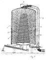
- the reactor device shown in FIG. 1 has a reactor vessel 1, in which an inner jacket 2, which tapers conically upwards, is received in a rotationally symmetrical manner.
- the outer wall 3 of the reactor vessel 1 and the inner wall 4 of the inner jacket 2 are gas and / or liquid permeable.
- the upper part of the inner jacket is covered by a cover 5.
- the inner casing 2 is rotatably arranged, which is represented by the suspension 6 designed as a shaft.
- an opening 7 is provided for feeding the bed.
- stirring arms 8 of the upper part of the reactor vessel 1 are rotatably arranged, for example connected to the shaft of the rotatable suspension 6.
- the outer wall 3 of the reactor vessel 1 is from an upper chamber 9 and a lower chamber 10 surround.
- Shovels are formed on the inner casing 2, which are designed as conveyor spirals in the exemplary embodiment shown.
- a discharge device 12, which is shown in more detail in FIG. 2, is arranged in the bottom of the reactor vessel 1.
- a rotating device 13 is provided, which is shown in the figure as a shaft to which blades 14 are attached.
- the reactor vessel is emptied through a shaft 15.
- the bed is introduced via the opening 7 into the rotationally symmetrical annular reactor space 16 formed between the inner jacket 2 and the outer wall 3 of the reactor vessel 1.
- the beds are of different nature depending on the intended use of the reactor device, for example filter materials are provided for filtering processes, or during drying processes the bedding can be formed as grain or the like.
- a fluid for example a gas, flows through the bed 16, which is let into the lower chamber 10 via the feed 17 and flows out through the outlet 18 at the upper chamber 9.
- the fluid is thus conducted in a simple cross-countercurrent, that is, it flows into the lower chamber 10, through the outer wall 6, through the bed 16 and the inner wall 4 into the interior of the inner jacket and from there back over the inner wall 4, the bed 16, the outer wall 3 in the upper chamber 9 and from there via the outlet 18 to the outside.
- the bed let in through the opening 7 is evenly distributed over the annular reactor chamber 16 with the aid of the stirring arms 8.
- the blades designed as conveying spirals 11 on the inner casing 2 promote the bed with the rotation upwards, loosening them up and distributing them evenly.
- the outer wall 3 and inner wall 4 are designed in such a way that they allow the fluid to flow through, while the beds cannot trickle through. For example, screen plates, stretch plates or conical individual segments can be provided.
- the blades 14 rotate and convey the bed inward from the annular reactor space to the shaft 16.
- 1 can be used for drying processes, purge gas pyrolysis, adsorption, filtration and the like.
- FIG. 3 An embodiment similar to FIG. 1 is shown in FIG. 3, a third chamber 19 being provided here.
- the inner jacket 2 has a separating surface 20 approximately in the middle. This arrangement enables the fluid to be guided twice in cross-countercurrent, which enables better countercurrent guidance or a better filter effect. 3 is for the same Applications such as the device according to FIG. 1 are provided.
- Fig. 4 shows a reactor device in which no second upper chamber is provided, but the fluid flows directly into the free environment. As in all of the exemplary embodiments, the flows of the fluid are represented by the arrows 21. 4 is particularly suitable for dryers or moving bed filters.
- Fig. 5 shows an embodiment which is particularly suitable for dryers and composting plants.
- a heat exchanger 22 is provided, which at least partially surrounds the outer wall 3 of the reactor vessel 1.
- the inflowing fluid 23 is guided through the heat exchanger 22, the outflowing fluid 24 providing the heat.
- a heat return from the outflowing fluid 24 to the inflowing fluid 23 is thus realized.
- This device can be used, for example, to create composting plants, since the composting process should provide as constant a temperature as possible.
- 25 water is additionally sprayed into the reactor space via a device.
- the bed preferably consists of a sand or ball bed which has a temperature gradient to the outside.
- a heating 26 of the interior or of the reactor space 16 is provided, which is realized via hot gases or fuel gases.
- the direction of flow of the fluid is in this embodiment changed periodically, this reversal being indicated by the arrows 27.
- the inflowing fluid which is preferably in the form of a gas, is heated in the bed, undergoes additional heating by the heating 26, and releases most of the heat back to the bed when it exits.
- the heat transfer is reversed.
- This embodiment of a regenerator is particularly useful when the pressure drop is to be particularly low and the bed is to be replaced continuously or discontinuously due to contamination.
- the compost to be treated is filled into the reactor vessel 1 from above.
- the heat exchanger 22 surrounds the reactor vessel 1 in the lower region and cold air 30 is introduced from below and heats up on the way up and penetrates through the permeable outer wall into the reactor space 16, flows through the compost inwards and then outwards again, whereby it absorbs the heat occurring during the treatment of the compost, and is passed downward via an annular space 32 and discharged via an outlet 31.
- the compost is thus flowed through in cross-direct current.
- the water required for the treatment of the compost is introduced in the region of the guide vanes 11 on the rotatable, conical inner jacket 2 or via the guide vanes 11 themselves.
Landscapes
- Chemical & Material Sciences (AREA)
- Chemical Kinetics & Catalysis (AREA)
- Organic Chemistry (AREA)
- Engineering & Computer Science (AREA)
- General Chemical & Material Sciences (AREA)
- Fluid Mechanics (AREA)
- General Engineering & Computer Science (AREA)
- Biochemistry (AREA)
- Microbiology (AREA)
- Molecular Biology (AREA)
- Life Sciences & Earth Sciences (AREA)
- Physics & Mathematics (AREA)
- Health & Medical Sciences (AREA)
- Mechanical Engineering (AREA)
- Biotechnology (AREA)
- Analytical Chemistry (AREA)
- Oil, Petroleum & Natural Gas (AREA)
- Devices And Processes Conducted In The Presence Of Fluids And Solid Particles (AREA)
- Structure Of Emergency Protection For Nuclear Reactors (AREA)
- Fertilizers (AREA)
- Filtering Of Dispersed Particles In Gases (AREA)
- Automatic Cycles, And Cycles In General (AREA)
- Physical Or Chemical Processes And Apparatus (AREA)
- Apparatus Associated With Microorganisms And Enzymes (AREA)
Description
- Die Erfindung betrifft eine Reaktorvorrichtung zur großflächigen Durchströmung von Wanderbettschüttungen nach dem Oberbegriff des Hauptanspruchs.
- Reaktorvorrichtungen zur großflächigen Durchströmung von Wanderbettschüttungen sind für eine Vielzahl von Anwendungsgebieten bekannt. Dabei sollen die Schüttungen mit verhältnismäßig großen Volumenströmen großflächig und gleichmäßig ohne Kanalbildungen durchströmt werden. Dies gilt beispielsweise für Trocknungsanlagen, Wärmeregeneratoren für die Nachverbrennung von Abgasen, Kompostanlagen, Wanderbettfilter, Spülgaspyrolysen und dergleichen. Solange die Schüttungen und Volumenströme verhältnismäßig klein sind, kann ein Reaktor von unten nach oben durchströmt werden, wobei die Schüttungen mit einem Rührarm oder einem Schieber egalisiert und am Reaktorboden zentral ausgetragen werden.
- Eine gleichmäßige Durchströmung wird aber bei großen Volumina wegen der erforderlichen Baugröße schwierig. Bei bekannten Schachtreaktoren werden Schüttungen, die zur Brückenbildung neigen, häufig ungleichmäßig durchströmt.
- Aus der US-A- 4 040 794 ist ein Wanderbettfilter bekannt, bei dem die Wanderbettschüttung in einem Ringraum mit gasdurchlässigen Wänden aufgenommen ist. Das Gas wird in die Mitte des Ringraums eingeleitet und strömt durch die Schüttung. Um. den Ringraum herum sind Ringkanäle mit Umlenkelementen angeordnet, durch die das durch die Schüttung strömende Gas wieder in die Schüttung zurückgelenkt wird.
- Der Erfindung liegt die Aufgabe zugrunde, eine Reaktorvorrichtung gemäß dem Oberbegriff des Hauptanspruchs zu schaffen, bei der große Durchströmungsquerschnitte bei verhältnismäßig niedriger durchströmter Schichthöhe zur Verfügung gestellt werden, wobei die Schüttung egalisiert und Brückenbildungen im der Schüttung vermieden werden sollen.
- Diese Aufgabe wird erfindungsgemäß durch die kennzeichnenden Merkmale des Hauptanspruchs in Verbindung mit den Merkmalen des Oberbegriffs gelöst. Dadurch, daß das Reaktorgefäß der Reaktorvorrichtung mit einer Innenwandung und einer Außenwandung derart ausgebildet ist, daß ein ringförmiger Reaktorraum gebildet wird und die Außen- und Innenwandungen gas- und/oder flüssigkeitsdurchlässig sind, wird eine großflächige gleichmäßige Durchströmung ermöglicht, wobei durch Drehen der Außenwandung und/oder der Innenwandung die Schüttung egalisiert wird und Brückenbildungen vermieden werden. Durch diese Bauart der Reaktorvorrichtung lassen sich bei verhältnismäßig großen Durchmessern und entsprechender Bauhöhe große Durchströmungsquerschnitte auch bei kleinen durchströmten Schichten realisieren, da der Durchströmungsquerschnitt durch die mittlere Manteloberfläche definiert wird.
- Durch die in den Unteransprüchen angegebenen Maßnahmen sind vorteilhafte Weiterbildungen und Verbesserungen möglich. Besonders vorteilhaft ist, daß das Fluid im Kreuzgegenstrom oder -gleichstrom geführt werden kann, wodurch Trocknungs- oder Filterwirkungen verbessert werden. Die vorgeschlagene Reaktorvorrichtung ist für zahlreiche Anwendungsgebiete einsetzbar, beispielsweise kann sie für Trocknungsvorgänge, Spülgaspyrolysen, Adsorptionen, Filtrationen, Kompostierungen oder als Regenarator für die Wärmeregenerierung verwendet werden.
- Ausführungsbeispiele der Erfindung sind in der Zeichnung dargestellt und werden in der nachfolgenden Beschreibung näher erläutert. Es zeigen:
- Fig. 1
- einen schematischen Längsschnitt durch eine Reaktorvorrichtung nach einem ersten Ausführungsbeispiel,
- Fig. 2
- eine Aufsicht auf den Boden des Reaktorgefäßes nach Fig. 1 mit einer Drehvorrichtung zur Austragung,
- Fig. 3
- einen schematischen Längsschnitt durch eine Reaktorvorrichtung gemäß einem zweiten Ausführungsbeispiel,
- Fig. 4
- einen Längsschnitt durch eine Reaktorvorrichtung nach einem dritten Ausführungsbeispiel,
- Fig. 5
- einen schematischen Längsschnitt durch eine Reaktorvorrichtung gemäß einem vierten Ausführungsbeispiel mit integriertem Wärmetauscher zur Anwendung als Trocknungs- oder Kompostanlage,
- Fig. 6
- einen Längsschnitt durch eine Reaktorvorrichtung gemäß einem fünften Ausführungsbeispiel zur Anwendung als Regenerator für die Wärmeregenerierung, und
- Fig. 7
- einen Längsschnitt durch eine Reaktoranordnung zur Anwendung als Kompostreaktor.
- Die in Fig. 1 dargestellte Reaktorvorrichtung weist ein Reaktorgefäß 1 auf, in dem rotationssymmetrisch ein sich nach oben konisch verjüngender Innenmantel 2 aufgenommen ist. Die Außenwandung 3 des Reaktorgefäßes 1 und die Innenwandung 4 des Innenmantels 2 sind gas- und/oder flüssigkeitsdurchlässig. Der obere Teil des Innenmantels ist durch eine Abdeckung 5 abgedeckt. Der Innenmantel 2 ist drehbar angeordnet, was durch die als Welle ausgebildete Aufhängung 6 dargestellt ist. Im oberen Teil des Reaktorgefäßes 1 ist eine Öffnung 7 zur Zuführung der Schüttung vorgesehen. Weiterhin sind Rührarme 8 des oberen Teils des Reaktorgefäßes 1 drehbar angeordnet, beispielsweise mit der Welle der drehbaren Aufhängung 6 verbunden.
- Die Außenwandung 3 des Reaktorgefäßes 1 wird von einer oberen Kammer 9 und einer unteren Kammer 10 umgeben. Auf dem Innenmantel 2 sind Schaufeln angeformt, die in dem dargestellten Ausführungsbeispiel als Förderspiralen ausgebildet sind. Im Boden des Reaktorgefäßes 1 ist eine Austragvorrichtung 12 angeordnet, die in Fig. 2 näher dargestellt ist. Danach ist eine Drehvorrichtung 13 vorgesehen, die in der Figur als Welle dargestellt ist, an der Schaufeln 14 befestigt sind. Durch einen Schacht 15 wird das Reaktorgefäß entleert.
- Die Schüttung wird über die Öffnung 7 in den zwischen Innenmantel 2 und Außenwandung 3 des Reaktorgefäßes 1 gebildeten rotationssymmetrischen ringförmigen Reaktorraum 16 eingeführt. Die Schüttungen sind je nach Verwendungszweck der Reaktorvorrichtung unterschiedlicher Natur, beispielsweise sind für Filtervorgänge Filtermaterialien vorgesehen oder bei Trocknungsvorgängen kann die Schüttung als Getreide oder dergleichen ausgebildet sein. Die Schüttung 16 wird von einem Fluid zum Beispiel einem Gas durchströmt, das in die untere Kammer 10 über die Zuführung 17 eingelassen wird und über den Auslaß 18 an der oberen Kammer 9 ausströmt. Das Fluid wird somit im einfachen Kreuzgegenstrom geführt, d.h., es strömt in die untere Kammer 10, durch die Außenwandung 6 hindurch, durch die Schüttung 16 und die Innenwandung 4 in den Innenraum des Innenmantels und von dort wieder zurück über die Innenwandung 4, die Schüttung 16, die Außenwandung 3 in die obere Kammer 9 und von dort über den Auslaß 18 nach außen.
- Die über die Öffnung 7 eingelassene Schüttung wird mit Hilfe der Rührarme 8 auf den ringförmigen Reaktorraum 16 gleichmäßig verteilt. Die als Förderspiralen 11 ausgebildeten Schaufeln auf dem Innenmantel 2 fördern die Schüttung mit der Drehung nach oben, wobei sie diese auflockern und gleichmäßig verteilen. Die Außenwandung 3 und Innenwandung 4 sind dabei derart ausgebildet, daß sie das Fluid hindurchströmen lassen, während die Schüttungen nicht hindurchrieseln können. Beispielsweise können Siebbleche, Streckbleche oder auch konusförmige Einzelsegmente vorgesehen sein.
- Zum Austrag der Schüttung, beispielsweise bei einem Filtervorgang der gesättigten Filtermaterialien oder bei einem Trocknungsvorgang des getrockneten Getreides, drehen sich die Schaufeln 14 und befördern die Schüttung vom ringförmigen Reaktorraum nach innen zu dem Schacht 16.
- Die Reaktorvorrichtung nach Fig. 1 kann für Trocknungsvorgänge, Spülgaspyrolysen, Adsorptionen, Filtrationen und dergleichen verwendet werden.
- In Fig. 3 ist ein zu Fig. 1 ähnliches Ausführungsbeispiel dargestellt, wobei hier eine dritte Kammer 19 vorgesehen ist. Außerdem weist der Innenmantel 2 etwa in der Mitte eine Trennfläche 20 auf. Diese Anordnung ermöglicht eine Führung des Fluids je zweimal im Kreuzgegenstrom, wodurch eine bessere Gegenstromführung oder eine bessere Filterwirkung ermöglicht wird. Diese Reaktorvorrichtung nach Fig. 3 ist für die gleichen Anwendungsfälle wie die Vorrichtung nach Fig. 1 vorgesehen.
- Fig. 4 zeigt eine Reaktorvorrichtung, bei der keine zweite obere Kammer vorgesehen ist, sondern das Fluid direkt in die freie Umgebung strömt. Die Strömungen des Fluids sind wie in allen Ausführungsbeispielen durch die Pfeile 21 dargestellt. Das Ausführungsbeispiel nach Fig. 4 ist vor allem für Trockner oder Wanderbettfilter geeignet.
- Fig. 5 zeigt ein Ausführungsbeispiel, das insbesondere für Trockner und Kompostanlagen geeignet ist. Dabei ist ein Wärmetauscher 22 vorgesehen, der zumindest teilweise die Außenwandung 3 des Reaktorgefäßes 1 umgibt. Dabei wird das einströmende Fluid 23 durch den Wärmetauscher 22 geführt, wobei das ausströmende Fluid 24 die Wärme zur Verfügung stellt. Es wird somit eine Wärmerückführung vom ausströmenden Fluid 24 zum einströmenden Fluid 23 realisiert. Durch diese Vorrichtung können beispielsweise Kompostanlagen erstellt werden, da bei dem Kompostierungsprozeß eine möglichst gleichbleibende Temperatur vorgesehen sein soll. Für eine Kompostanlage wird zusätzlich über eine Vorrichtung 25 Wasser in den Reaktorraum eingesprüht.
- In Fig. 6 ist ein Regenerator für die Wärmeregenerierung dargestellt. Dabei besteht die Schüttung vorzugsweise aus einem Sand- oder Kugelbett, das nach außen einen Temperaturgradienten aufweist. Bei dieser Vorrichtung ist eine Beheizung 26 des Innenraums bzw. des Reaktorraums 16 vorgesehen, die über heiße Gase oder Brenngase realisiert wird. Die Strömungsrichtung des Fluids wird bei diesem Ausführungsbeispiel periodisch gewechselt, wobei diese Umkehrung durch die Pfeile 27 angedeutet wird. Das einströmende Fluid, das vorzugsweise als Gas ausgebildet wird, wird dabei in der Schüttung erwärmt, erfährt eine zusätzliche Erwärmung durch die Beheizung 26 und gibt beim Austritt den größten Teil der Wärme wieder an die Schüttung ab. Beim Wechsel der Strömungsrichtung erfolgt eine Umkehrung des Wärmeüberganges. Diese Ausführungsform eines Regenerators ist insbesondere dann sinnvoll, wenn der Druckverlust besonders gering sein soll und die Schüttung wegen Verschmutzung kontinuierlich oder diskontinuierlich ausgetauscht werden soll.
- Fig. 7 zeigt ein weiteres Ausführungsbeispiel der Reaktorvorrichtung zur Kompostierung. Der zu behandelnde Kompost wird von oben her in das Reaktorgefäß 1 eingefüllt. Der Wärmetauscher 22 umgibt das Reaktorgefäß 1 im unteren Bereich und kalte Luft 30 wird von unten her eingeführt und erwärmt sich auf dem Weg nach oben und dringt durch die durchlässige Außenwandung in den Reaktorraum 16, durchströmt den Kompost nach innen und dann wieder nach außen, wobei sie die bei der Behandlung des Komposts auftretende Wäme aufnimmt, und wird über einen Ringraum 32 nach unten geleitet und über einen Auslaß 31 abgeführt. Somit wird der Kompost im Kreuzgleichstrom durchströmt.
- Das für die Behandlung des Komposts notwendige Wasser wird im Bereich der Leitschaufeln 11 an dem drehbaren, konusförmigen Innenmantel 2 beziehungsweise über die Leitschaufeln 11 selbst eingeführt.
- Durch die Anordnung des Wärmetauschers 22 im unteren Bereich, die Durchströmung des Komposts im Kreuzgleichstrom und durch die Wassereinbringung an den über die am Innenmantel 2 angeordneten Leitschaufeln wird eine gleichmäßige Luftfeuchtigkeit und Temperatur in dem Reaktorraum 16 erzielt.
Claims (13)
- Reaktorvorrichtung zur großflächigen Durchströmung von Wanderbettschüttungen mittels eines Fluids mit einem einen Einlaß für die Schüttung aufweisenden Reaktorgefäß, in dem die Wanderbettschüttung aufgenommen ist, wobei zwischen einer Innenwandung und der Außenwandung des Reaktorgefäßes ein radialsymmetrischer ringförmiger Reaktorraum gebildet ist, und die Außen- und Innenwandungen zur radialen Durchströmung des Fluids gas- und/oder flüssigkeitsdurchlässig sind,
dadurch gekennzeichnet,
daß die Innenwandung (4) und/oder die Außenwandung (3) zur Egalisierung der Schüttung und Vermeidung von Brückenbildungen drehbar angeordnet sind. - Vorrichtung nach Anspruch 1, dadurch gekennzeichnet, daß die Zuführung (17) und der Auslaß (18,3) für das Fluid und Umlenkanordnungen derart vorgesehen sind, daß das Fluid zur Durchströmung der Schüttung von außen nach innen und/oder innen nach außen in radialer Richtung im Kreuzstrom, Kreuzgleichstrom oder Kreuzgegenstrom geführt ist.
- Vorrichtung nach einem der Ansprüche 1 bis 2, dadurch gekennzeichnet, daß an der drehbaren Innen- und/oder Außenwandung (3,4) zum Reaktorraum (16) gerichtete Leitschaufeln (11) angeordnet sind, die die Schüttung infolge der Drehbewegung auflockern.
- Vorrichtung nach einem der Ansprüche 1 bis 3, dadurch gekennzeichnet, daß im Bereich des Einlasses (7) für die Schüttung eine mit der drehbaren Innen- und/oder Außenwandung verbundene Verteilvorrichtung (8) vorgesehen ist, die die Schüttung im Einlaß auf den gesamten Querschnitt des Reaktorraums (16) verteilt.
- Vorrichtung nach einem der Ansprüche 1 bis 4, dadurch gekennzeichnet, daß die drehbare Innenwandung (4) als sich nach oben konisch verjüngender Innenmantel (2) ausgebildet ist und daß die Leitschaufeln (11) derart an dem Innenmantel (2) angeordnet sind, daß die Auflockerung der Schüttung vorzugsweise nach oben erfolgt.
- Vorrichtung nach einem der Ansprüche 1 bis 5, dadurch gekennzeichnet, daß die Außenwandung (3) des Reaktorgefäßes (1) mit zwei übereinanderliegenden Kammern (9,10) umgeben ist, wobei die Zuführung (17) mit der Kammer (10) und der Auslaß (18) mit der Kammer (9) derart in Verbindung stehen, daß das die Schüttung durchströmende Fluid zunächst durch die Kammer (10) radialsymmetrisch von außen in Kreuzstrom durch die Schüttung geführt und dann von innen im Kreuzgegenstrom durch die zweite Kammer (9) geführt ist.
- Vorrichtung nach Anspruch 6, dadurch gekennzeichnet, daß die zweite Kammer (9) keine Außenwand aufweist und das Fluid direkt ins Freie ausströmt.
- Vorrichtung nach einem der Ansprüche 1 bis 7, dadurch gekennzeichnet, daß eine Vorrichtung (26) zur Zuführung von heißen Gasen und/oder Brenngasen vorgesehen ist, die das Fluid erwärmen.
- Vorrichtung nach einem der Ansprüche 1 bis 8, dadurch gekennzeichnet, daß das durchströmende Fluid periodisch in seiner Strömungsrichtung geändert wird.
- Vorrichtung nach einem der Ansprüche 1 bis 9, dadurch gekennzeichnet, daß ein Wärmetauscher (22) vorgesehen ist, durch den das einströmende Fluid (23) durch das ausströmende Fluid (24) erwärmt wird.
- Vorrichtung nach Anspruch 10. dadurch gekennzeichnet, daß der Wärmetauscher (22) die Außenwandung (3) des Reaktorgefäßes (1) zumindest teilweise umgibt.
- Vorrichtung nach einem der Ansprüche 1 bis 11, dadurch gekennzeichnet, daß zur Anwendung für einen Kompostierungsprozeß eine Vorrichtung (25) zur Zuführung von Wasser in den Reaktorraum (16) vorgesehen ist.
- Vorrichtung nach einem der Ansprüche 1 bis 12, dadurch gekennzeichnet, daß am Boden des Reaktorgefäßes (1) eine Drehvorrichtung (13) mit Schaufeln (14) zur gleichmäßigen Austragung der Schüttung angeordnet ist.
Priority Applications (1)
| Application Number | Priority Date | Filing Date | Title |
|---|---|---|---|
| AT89730111T ATE87844T1 (de) | 1988-05-02 | 1989-04-27 | Reaktorvorrichtung zur grossflaechigen durchstroemung von wanderbettschuettungen. |
Applications Claiming Priority (2)
| Application Number | Priority Date | Filing Date | Title |
|---|---|---|---|
| DE3815346 | 1988-05-02 | ||
| DE19883815346 DE3815346A1 (de) | 1988-05-02 | 1988-05-02 | Reaktorvorrichtung zur grossflaechigen durchstroemung von wanderbettschuettungen |
Publications (3)
| Publication Number | Publication Date |
|---|---|
| EP0341196A2 EP0341196A2 (de) | 1989-11-08 |
| EP0341196A3 EP0341196A3 (en) | 1990-05-30 |
| EP0341196B1 true EP0341196B1 (de) | 1993-04-07 |
Family
ID=6353723
Family Applications (1)
| Application Number | Title | Priority Date | Filing Date |
|---|---|---|---|
| EP19890730111 Expired - Lifetime EP0341196B1 (de) | 1988-05-02 | 1989-04-27 | Reaktorvorrichtung zur grossflächigen Durchströmung von Wanderbettschüttungen |
Country Status (6)
| Country | Link |
|---|---|
| EP (1) | EP0341196B1 (de) |
| JP (1) | JPH0214734A (de) |
| AT (1) | ATE87844T1 (de) |
| DE (2) | DE3815346A1 (de) |
| DK (1) | DK211889A (de) |
| ES (1) | ES2039930T3 (de) |
Families Citing this family (10)
| Publication number | Priority date | Publication date | Assignee | Title |
|---|---|---|---|---|
| EP0583488A1 (de) * | 1991-01-25 | 1994-02-23 | ISODRA isolierte Feindrähte GmbH Wildenkuhlen | Verfahren zur biologischen Behandlung von Abgasen und Einrichtung zur Ausführung des Verfahrens |
| ES2106258T3 (es) * | 1992-12-22 | 1997-11-01 | Sanyo Electric Co | Procedimiento y sistema de eliminacion de desechos organicos. |
| DE4339006C2 (de) * | 1993-11-11 | 2002-10-24 | Alfred Schymalla | Vorrichtung zur Umsetzung von Flüssigkeiten und Gasen an Feststoffen |
| DK172537B1 (da) * | 1996-07-30 | 1998-11-30 | Smidth & Co As F L | Indretning til varmeveksling |
| JP4552474B2 (ja) * | 2004-03-24 | 2010-09-29 | Jfeスチール株式会社 | 排ガス処理装置 |
| WO2008051876A2 (en) * | 2006-10-20 | 2008-05-02 | Don Shubin | Systems and methods for dewatering and treating waste |
| ITVR20080024A1 (it) * | 2008-02-18 | 2009-08-19 | Moretto Spa | Struttura di tramoggia |
| SE533607C2 (sv) * | 2009-03-13 | 2010-11-02 | Tomas Aabyhammar Med Scandry Fa | Anordning för torkning av partikelformigt material med en gas |
| DE102011111955A1 (de) * | 2011-08-30 | 2013-02-28 | Linde Aktiengesellschaft | Kolonne |
| CN116943546A (zh) * | 2022-04-20 | 2023-10-27 | 中国石油化工股份有限公司 | 一种下进上出径向移动床反应器 |
Family Cites Families (5)
| Publication number | Priority date | Publication date | Assignee | Title |
|---|---|---|---|---|
| GB329827A (en) * | 1929-05-14 | 1930-05-29 | Constantine Theodorovitch Drig | Improvements in or connected with low temperature carbonization retorts |
| FR781420A (fr) * | 1934-02-06 | 1935-05-15 | Socea | Trappe pour cellules ou analogues, destinées notamment au traitement des ordures ménagères |
| DE646182C (de) * | 1935-07-04 | 1937-06-10 | Hermann Niggemann Dr | Verfahren und Vorrichtung zum Schwelen von bituminoesen Brennstoffen |
| US4040794A (en) * | 1975-10-24 | 1977-08-09 | Uop Inc. | Moving bed contacting process and apparatus |
| DE3708049A1 (de) * | 1986-03-13 | 1987-09-17 | Zenata Nv | Vorrichtung und verfahren zur behandlung von kohle und schiefer |
-
1988
- 1988-05-02 DE DE19883815346 patent/DE3815346A1/de not_active Withdrawn
-
1989
- 1989-04-27 AT AT89730111T patent/ATE87844T1/de not_active IP Right Cessation
- 1989-04-27 EP EP19890730111 patent/EP0341196B1/de not_active Expired - Lifetime
- 1989-04-27 DE DE8989730111T patent/DE58903996D1/de not_active Expired - Fee Related
- 1989-04-27 ES ES89730111T patent/ES2039930T3/es not_active Expired - Lifetime
- 1989-05-01 DK DK211889A patent/DK211889A/da not_active Application Discontinuation
- 1989-05-02 JP JP1113595A patent/JPH0214734A/ja active Pending
Also Published As
| Publication number | Publication date |
|---|---|
| DK211889A (da) | 1989-11-03 |
| JPH0214734A (ja) | 1990-01-18 |
| ATE87844T1 (de) | 1993-04-15 |
| EP0341196A2 (de) | 1989-11-08 |
| DE3815346A1 (de) | 1989-11-16 |
| ES2039930T3 (es) | 1993-10-01 |
| DK211889D0 (da) | 1989-05-01 |
| EP0341196A3 (en) | 1990-05-30 |
| DE58903996D1 (de) | 1993-05-13 |
Similar Documents
| Publication | Publication Date | Title |
|---|---|---|
| EP0341196B1 (de) | Reaktorvorrichtung zur grossflächigen Durchströmung von Wanderbettschüttungen | |
| DE3844422A1 (de) | Verfahren und vorrichtung zum abtrennen unerwuenschter bestandteile aus einem abgas | |
| EP0270531B2 (de) | Wanderbettreaktor | |
| DE3314887A1 (de) | Gasverteilboden fuer trockner od.dgl. mit kreisendem fliessbett | |
| DE4118433C2 (de) | Fließbettapparatur zum Behandeln partikelförmigen Gutes | |
| EP0202411B1 (de) | Verfahren und Vorrichtung zur Rauchgasreinigung bei Feuerungsanlagen | |
| AT389822B (de) | Verfahren zum kontinuierlichen reinigen von gasen von mitgefuehrten beladestoffen sowie vorrichtung zu seiner durchfuehrung | |
| DE2951279C2 (de) | ||
| DE3408627A1 (de) | Vorrichtung zum entstauben von heissen gasen | |
| JPH04219112A (ja) | 主に排気ガス処理のための移動層反応器 | |
| DE2909647C2 (de) | Verfahren und Vorrichtung zur Reinigung von Gichtgas | |
| EP0211343B1 (de) | Vorrichtung zum Behandeln von Substanzen in einem Gasstrom | |
| DE19728332C2 (de) | Verfahren und Vorrichtung zum Vorwärmen und/oder Trocknen von glasbildendem Beschickungsgut mittels Abgasen von Glasschmelzöfen | |
| DE3875801T2 (de) | Substanzbehandlung. | |
| EP0111615B1 (de) | Wärmeübertragersystem, vorzugsweise für ein Prozessgas | |
| EP0290870B1 (de) | Einrichtung zum gesteuerten Abzug möglichst planparalleler Schichten fliessfähigen Schüttgutes an der Unterseite einer in einem kreiszylindrischen Behälter enthaltenen Schüttgutsäule und Verwendung bei einem Wanderbettfilter | |
| DE4040246A1 (de) | Wanderbettreaktor, insbesondere zur behandlung von rauchgasen | |
| DE3917325A1 (de) | Konverter fuer die katalytische umsetzung von gasfoermigen bestandteilen in gasen | |
| DE3422045A1 (de) | Verfahren und biofiltereinrichtung zur biologischen abluftreinigung | |
| EP0556368B1 (de) | Schüttgutreaktor | |
| DE1501369B2 (de) | Schachtförmiger Wärmetauscher | |
| DE69414161T2 (de) | Staubabscheider für heisse Gase | |
| DE632705C (de) | Verfahren und Vorrichtung zum Formen, Trocknen, Erhitzen und Vorbrennen klebenden Gutes | |
| DE2849053C2 (de) | Feststoff-Gas-Wärmetauscher | |
| EP0295213A1 (de) | Wirbelschichtanlage mit Abluftfilter |
Legal Events
| Date | Code | Title | Description |
|---|---|---|---|
| PUAI | Public reference made under article 153(3) epc to a published international application that has entered the european phase |
Free format text: ORIGINAL CODE: 0009012 |
|
| AK | Designated contracting states |
Kind code of ref document: A2 Designated state(s): AT BE CH DE ES FR GB GR IT LI LU NL SE |
|
| PUAL | Search report despatched |
Free format text: ORIGINAL CODE: 0009013 |
|
| AK | Designated contracting states |
Kind code of ref document: A3 Designated state(s): AT BE CH DE ES FR GB GR IT LI LU NL SE |
|
| 17P | Request for examination filed |
Effective date: 19900817 |
|
| 17Q | First examination report despatched |
Effective date: 19910627 |
|
| GRAA | (expected) grant |
Free format text: ORIGINAL CODE: 0009210 |
|
| ITF | It: translation for a ep patent filed | ||
| AK | Designated contracting states |
Kind code of ref document: B1 Designated state(s): AT BE CH DE ES FR GB GR IT LI LU NL SE |
|
| PG25 | Lapsed in a contracting state [announced via postgrant information from national office to epo] |
Ref country code: GR Free format text: LAPSE BECAUSE OF FAILURE TO SUBMIT A TRANSLATION OF THE DESCRIPTION OR TO PAY THE FEE WITHIN THE PRESCRIBED TIME-LIMIT Effective date: 19930407 |
|
| REF | Corresponds to: |
Ref document number: 87844 Country of ref document: AT Date of ref document: 19930415 Kind code of ref document: T |
|
| ET | Fr: translation filed | ||
| REF | Corresponds to: |
Ref document number: 58903996 Country of ref document: DE Date of ref document: 19930513 |
|
| GBT | Gb: translation of ep patent filed (gb section 77(6)(a)/1977) |
Effective date: 19930428 |
|
| REG | Reference to a national code |
Ref country code: ES Ref legal event code: FG2A Ref document number: 2039930 Country of ref document: ES Kind code of ref document: T3 |
|
| PLBE | No opposition filed within time limit |
Free format text: ORIGINAL CODE: 0009261 |
|
| STAA | Information on the status of an ep patent application or granted ep patent |
Free format text: STATUS: NO OPPOSITION FILED WITHIN TIME LIMIT |
|
| 26N | No opposition filed | ||
| ITTA | It: last paid annual fee | ||
| EPTA | Lu: last paid annual fee | ||
| EAL | Se: european patent in force in sweden |
Ref document number: 89730111.5 |
|
| PGFP | Annual fee paid to national office [announced via postgrant information from national office to epo] |
Ref country code: ES Payment date: 20000407 Year of fee payment: 12 |
|
| PGFP | Annual fee paid to national office [announced via postgrant information from national office to epo] |
Ref country code: LU Payment date: 20000410 Year of fee payment: 12 |
|
| PGFP | Annual fee paid to national office [announced via postgrant information from national office to epo] |
Ref country code: BE Payment date: 20000413 Year of fee payment: 12 |
|
| PGFP | Annual fee paid to national office [announced via postgrant information from national office to epo] |
Ref country code: SE Payment date: 20000417 Year of fee payment: 12 |
|
| PGFP | Annual fee paid to national office [announced via postgrant information from national office to epo] |
Ref country code: GB Payment date: 20000419 Year of fee payment: 12 |
|
| PGFP | Annual fee paid to national office [announced via postgrant information from national office to epo] |
Ref country code: AT Payment date: 20000421 Year of fee payment: 12 |
|
| PGFP | Annual fee paid to national office [announced via postgrant information from national office to epo] |
Ref country code: NL Payment date: 20000428 Year of fee payment: 12 Ref country code: FR Payment date: 20000428 Year of fee payment: 12 |
|
| PGFP | Annual fee paid to national office [announced via postgrant information from national office to epo] |
Ref country code: DE Payment date: 20000518 Year of fee payment: 12 |
|
| PGFP | Annual fee paid to national office [announced via postgrant information from national office to epo] |
Ref country code: CH Payment date: 20000629 Year of fee payment: 12 |
|
| PG25 | Lapsed in a contracting state [announced via postgrant information from national office to epo] |
Ref country code: LU Free format text: LAPSE BECAUSE OF NON-PAYMENT OF DUE FEES Effective date: 20010427 Ref country code: GB Free format text: LAPSE BECAUSE OF NON-PAYMENT OF DUE FEES Effective date: 20010427 Ref country code: AT Free format text: LAPSE BECAUSE OF NON-PAYMENT OF DUE FEES Effective date: 20010427 |
|
| PG25 | Lapsed in a contracting state [announced via postgrant information from national office to epo] |
Ref country code: SE Free format text: LAPSE BECAUSE OF NON-PAYMENT OF DUE FEES Effective date: 20010428 Ref country code: ES Free format text: LAPSE BECAUSE OF NON-PAYMENT OF DUE FEES Effective date: 20010428 |
|
| PG25 | Lapsed in a contracting state [announced via postgrant information from national office to epo] |
Ref country code: FR Free format text: THE PATENT HAS BEEN ANNULLED BY A DECISION OF A NATIONAL AUTHORITY Effective date: 20010430 Ref country code: BE Free format text: LAPSE BECAUSE OF NON-PAYMENT OF DUE FEES Effective date: 20010430 |
|
| PG25 | Lapsed in a contracting state [announced via postgrant information from national office to epo] |
Ref country code: LI Free format text: LAPSE BECAUSE OF NON-PAYMENT OF DUE FEES Effective date: 20010526 Ref country code: CH Free format text: LAPSE BECAUSE OF NON-PAYMENT OF DUE FEES Effective date: 20010526 |
|
| BERE | Be: lapsed |
Owner name: MICHEL-KIM HERWIG Effective date: 20010430 |
|
| PG25 | Lapsed in a contracting state [announced via postgrant information from national office to epo] |
Ref country code: NL Free format text: LAPSE BECAUSE OF NON-PAYMENT OF DUE FEES Effective date: 20011101 |
|
| EUG | Se: european patent has lapsed |
Ref document number: 89730111.5 |
|
| REG | Reference to a national code |
Ref country code: CH Ref legal event code: PL |
|
| GBPC | Gb: european patent ceased through non-payment of renewal fee |
Effective date: 20010427 |
|
| NLV4 | Nl: lapsed or anulled due to non-payment of the annual fee |
Effective date: 20011101 |
|
| PG25 | Lapsed in a contracting state [announced via postgrant information from national office to epo] |
Ref country code: DE Free format text: LAPSE BECAUSE OF NON-PAYMENT OF DUE FEES Effective date: 20020201 |
|
| REG | Reference to a national code |
Ref country code: FR Ref legal event code: ST |
|
| REG | Reference to a national code |
Ref country code: ES Ref legal event code: FD2A Effective date: 20030303 |
|
| PG25 | Lapsed in a contracting state [announced via postgrant information from national office to epo] |
Ref country code: IT Free format text: LAPSE BECAUSE OF NON-PAYMENT OF DUE FEES;WARNING: LAPSES OF ITALIAN PATENTS WITH EFFECTIVE DATE BEFORE 2007 MAY HAVE OCCURRED AT ANY TIME BEFORE 2007. THE CORRECT EFFECTIVE DATE MAY BE DIFFERENT FROM THE ONE RECORDED. Effective date: 20050427 |