EP0340452A2 - Dispositif de réglage en rotation d'un cylindre d'un dispositif de retournement et dispositif de déplacement axial d'un élément de réglage pour le changement de la position des pinces de ce cylindre dans une rotative d'impression de feuilles - Google Patents
Dispositif de réglage en rotation d'un cylindre d'un dispositif de retournement et dispositif de déplacement axial d'un élément de réglage pour le changement de la position des pinces de ce cylindre dans une rotative d'impression de feuilles Download PDFInfo
- Publication number
- EP0340452A2 EP0340452A2 EP89105685A EP89105685A EP0340452A2 EP 0340452 A2 EP0340452 A2 EP 0340452A2 EP 89105685 A EP89105685 A EP 89105685A EP 89105685 A EP89105685 A EP 89105685A EP 0340452 A2 EP0340452 A2 EP 0340452A2
- Authority
- EP
- European Patent Office
- Prior art keywords
- cylinder
- adjusting
- adjusting member
- pressure
- spring force
- Prior art date
- Legal status (The legal status is an assumption and is not a legal conclusion. Google has not performed a legal analysis and makes no representation as to the accuracy of the status listed.)
- Granted
Links
- 238000006243 chemical reaction Methods 0.000 title claims abstract description 9
- 230000008878 coupling Effects 0.000 claims abstract description 11
- 238000010168 coupling process Methods 0.000 claims abstract description 11
- 238000005859 coupling reaction Methods 0.000 claims abstract description 11
- 230000000295 complement effect Effects 0.000 claims 1
- 238000006073 displacement reaction Methods 0.000 abstract description 3
- 238000000034 method Methods 0.000 description 4
- 230000008569 process Effects 0.000 description 4
- 230000005540 biological transmission Effects 0.000 description 2
- 230000007246 mechanism Effects 0.000 description 2
- 230000008901 benefit Effects 0.000 description 1
- 230000006835 compression Effects 0.000 description 1
- 238000007906 compression Methods 0.000 description 1
- 238000010276 construction Methods 0.000 description 1
- 238000011161 development Methods 0.000 description 1
- 230000018109 developmental process Effects 0.000 description 1
- 230000006872 improvement Effects 0.000 description 1
- 230000003287 optical effect Effects 0.000 description 1
- 230000009467 reduction Effects 0.000 description 1
- 238000005096 rolling process Methods 0.000 description 1
- 238000009827 uniform distribution Methods 0.000 description 1
Images


Classifications
-
- B—PERFORMING OPERATIONS; TRANSPORTING
- B41—PRINTING; LINING MACHINES; TYPEWRITERS; STAMPS
- B41F—PRINTING MACHINES OR PRESSES
- B41F21/00—Devices for conveying sheets through printing apparatus or machines
- B41F21/10—Combinations of transfer drums and grippers
-
- B—PERFORMING OPERATIONS; TRANSPORTING
- B41—PRINTING; LINING MACHINES; TYPEWRITERS; STAMPS
- B41F—PRINTING MACHINES OR PRESSES
- B41F13/00—Common details of rotary presses or machines
- B41F13/0008—Driving devices
Definitions
- the invention relates to a device for adjusting the rotational position between a fixed gear and an adjusting gear arranged coaxially therewith and for changing the gripper by axially displacing an actuator on a cylinder of the turning device of a sheet-fed rotary printing press, which has generic features according to the preamble of claim 1.
- a device of this type is known from DE-OS 36 11 325.
- the adjusting member of this arrangement is adjustable by means of a thread in a way which comprises a first section in which the spring force acting on the pressure levers increases from a low value to a maximum value and a second section in which while maintaining the maximum on the pressure levers acting spring force an electrical switch for the supply circuit of the drive device can be actuated, so that the supply circuit can only be closed when the coupling between the fixed gear and the adjusting gear is fully effective.
- the supply circuit is first interrupted before the frictional coupling between the fixed gear and the adjusting gear can be released. In this way it is ensured that the machine can only be put into operation when the adjusting gear is non-positively coupled to the fixed gear, that is to say when the clamping between the two gears is firmly tightened.
- the axial displacement of the adjusting member for converting the grippers takes place in a design known from DE-PS 26 20 392 by an eccentric mechanism made of an eccentric bolt rotatably mounted in the adjusting member and an eccentric pin engaging in a guide of the cylinder.
- the adjusting member is secured with fastening screws in relation to the cylinder, so that it is necessary for the displacement of the adjusting member to climb the printing machine in order to loosen the fastening screws of the adjusting member, the actuating member of the eccentric with a suitable tool from one to the opposite end position to twist and then tighten the fastening screws again.
- an electrical end position protection is also known from this document. The end position lock works independently of the previously mentioned securing of the clamping between the fixed gear and the adjusting gear.
- the object on which the invention is based is derived from safeguarding the changeover process on the turning device better than hitherto against incorrect operation.
- the aim is to simplify the changeover process in order to reduce set-up times during the changeover process while avoiding incorrect operation.
- the invention solves this problem with a device of the type mentioned at the beginning and with features according to the characterizing part of patent claim 1.
- the new training features while maintaining the advantage of a clamping force independent of the operator of the machine for the non-positive coupling of the fixed gear and the adjusting gear, transmit the reaction force of the spring force to at least one clamping body, which firmly connects the adjusting member for the gripper changeover to the cylinder as soon as and as long as the fixed gear is non-positively coupled to the adjusting gear, so that the adjusting member for the gripper changeover in the operating position of the machine is now firmly connected to the cylinder and is thereby mechanically secured as a function of the effective clamping of the two gears. Electrical or mechanical precautions must be taken to ensure that this mechanical protection is only possible in the positioned positions, in particular end positions. This also achieves greater safety because both clamping processes are protected by only one switch, and an electrical signal can be used for the optical and / or acoustic display of the intact clamping.
- the characterizing part of claim 2 contains an advantageous embodiment of the features of the invention with the aim of using the simplest possible components for the transmission of the reaction force from the spring force for clamping the adjusting member on the cylinder.
- the features of claims 3 to 6 also serve this purpose in a more appropriate manner
- a further improvement of the solution of the object according to the invention is achieved according to a particular inventive idea with a device in which the actuator which is axially displaceable relative to the cylinder of the turning device can be adjusted by means of a rotatable eccentric for converting the gripper control, the eccentric pin in one part and the eccentric pin in the other part is performed if this training is developed with features according to the characterizing part of claim 7.
- Claims 8 to 14 contain advantageous developments of this inventive concept with regard to simple components and their trouble-free function.
- the claims 11 and 12 relate to means known per se from DE-PS 26 20 392 for securing the end positions of the axially movable actuator for gripper changeover.
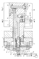
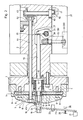
- a fixed gear 1 is attached to one end of a cylinder 2 of a turning device, which is shown only partially in the drawing for reasons of better clarity, by means of a plurality of screws 3 distributed over the circumference, of which only one is shown.
- the fixed gear 1 has an angular recess in the axial plane section, which forms a pin extension 4, on which the ring-shaped adjusting gear 5 is arranged so as to be adjustable in angle of rotation relative to the fixed gear 1. Both gears 1 and 5 can be non-positively coupled to one another by clamping.
- a support plate 7 is fastened to the end face of the pin extension 4 with a plurality of screws 6, against which a plurality, in the exemplary embodiment six, of pressure levers 8 are supported, which extend radially in a uniform distribution over the circumference.
- One end of this pressure lever 8 lies against a radial annular surface 9 on the adjusting gear 5 and the other end against a disc 10 which forms the spring-loaded pressure member, the pressure levers 8 being supported on the opposite side with cams 11 against the support plate 7.
- the cams 11 are arranged to increase the clamping force with little effort almost at one end of the pressure lever 8, but still between their supports on the adjusting gear and on the disc, so that the pressure levers 8 form double levers with lever arms of different lengths.
- the disk 10 is guided in an axially movable manner on a pressure rod 12, which in turn is axially movable in the shaft 2 parallel to its axis and has a radial flange 13 which forms an abutment for a compression spring 14.
- a column of several layered disc springs is provided, which are supported on the other hand against the disc 10, so that it loads the pressure lever 8 at the ends of the long lever arms with the spring force from the spring 14 and thus independently of a physical force.
- a pin 15 engages with its ends in bores on the one hand in the radial flange 13 and on the other hand in the cylinder 2 and secures the push rod 12 against rotation.
- a pressure ring 16 with an integrated roller bearing 17 adjoins the section of the pressure rod 12 passing through the spring 14 in the area of the pressure lever 8, one end of the pressure ring 16 abutting the disk 10 and a threaded sleeve 18 movable against the other end thereof, whose nut thread can be screwed onto a bolt thread at the free, outwardly directed end of the push rod by an actuator, for example a hexagon head 19.
- a game 20 is provided, so that the threaded sleeve 18 must be moved axially for releasing the coupling which causes the coupling between the fixed gear 1 and the adjusting gear 5 on this play before this in a second Section of the movement the threaded sleeve 18 forces can be exerted on the pressure ring 16 in order to displace it with the disk against the spring force of the spring 14 and thereby relieve the pressure lever 8.
- the threaded sleeve 18 moves in the opposite direction, the full spring force of the spring 14 is again effective on the pressure lever 8 before the threaded sleeve 18 moves on the portion of the play.
- a switch 21 located in the supply circuit of the machine.
- a double lever 23 which is fixed to the machine at 22, engages with one end in an annular groove 24 on the circumference of the threaded sleeve 18.
- the other end acts on the actuating member of the switch 21 and extends between a stop 25 and a spring 26, so that the stop 25 limits the movement of the threaded sleeve 18 to the outside, and thus their movement on the section determining the play 20.
- the spring 26 provides for a return of the double lever 23 to the stop position, in which the switch 21 releases the circuit of the machine when the clamp is tightened, that is to say the frictional coupling of the two gear wheels 1 and 5.
- FIG. 1 shows the state of the released clamping, in which the threaded sleeve 18 was first screwed to the right by the path of the game 20 in the plane of the drawing and the switch 21 to interrupt the circuit in the drive has operated the machine before the pressure ring 16 has been axially displaced against the disk 10 to reduce or cancel the spring force on the ends of the pressure lever 8.
- the pressure ring 16 is arranged on a step of the pressure rod 12 which has a smaller diameter than the part passing through the spring 14, so that a step-shaped stop is formed for the movement of the pressure ring 16.
- the inward-facing end of the pressure rod 12 opposite the bolt thread acts against a second, angularly shaped pressure lever 27 which is movable in the cylinder 2 in the region of the axially movable adjusting member 28 about an articulated bolt 29 arranged transversely to the longitudinal axis of the shaft 2.
- the other arm of the angularly shaped pressure lever 27 engages approximately centrally under a clamping bracket 30, the ends of which are each connected by a tension bolt 31 and 32 to clamping pieces 54 and 55 arranged in outer recesses of the adjusting member 28, which are connected to the ends of the clamping bracket via washers 33 and 34 30 act.
- the tension bolts 31 and 32 engage behind the clamping bracket 30 with a collar head and are guided through bores in the clamping bracket 30 and the adjusting member 28.
- the push rod 12 transmits the spring force of the spring 14 via the angular pressure lever 27 to the clamping bracket 30, so that the spring force acts via the tension bolts 31 and 32 as a clamping force on the clamping pieces 54 and 55 and presses the adjusting member 28 against seat surfaces formed on the shaft 2 .
- one arm of the pressure lever 27 and the clamping bracket 30 touch with spherical surfaces, which can optionally be formed by pressure disks made of a wear-resistant material.
- the clamping pieces 54 and 55 are screwable on the free ends of the tension bolts 31 and 32 to allow adjustment of the clamping forces and a play 35 between the push rod 12 and the transmission members and to ensure that the adjusting member 28 is axially movable when the Spring 14 for reducing or canceling the spring force acting on the pressure lever 8 is compressed, wherein the push rod 12 is in the Drawing moves to the left until the pressure ring 16 touches the stop shoulder of the push rod 12.
- the game 35 between the push rod 12 and the intermediate members of the clamping of the axially movable adjusting member 28 is therefore visible when the clamping is released.
- the game 20 between the threaded sleeve 18 and the pressure ring 16 is visible when the clamp is tightened.
- the axially movable adjustment member 28 for gripper changeover is designed as a slide that extends across the width of the machine and is guided in a recess in the cylinder 2 on guide strips 38 and 39 that can be adjusted by screws 36 and 37 on the drive side and on the operating side. A clamping of the adjusting member 28 on only one side is therefore sufficient.
- an eccentric mechanism is provided which, in contrast to known designs, is provided in the cylinder 2 about an eccentric bolt 40 mounted transversely to its axis and an eccentric pin 41 engaging in a bearing 56 of the adjusting member 28.
- the bearing 56 consists, for example, of a circuit board made of a wear-resistant material.
- the eccentric bolt 40 is adjusted by means of an angular gear, likewise mounted in the cylinder 2, from the two bevel gears 42 and 43 via a selector shaft 44, which is rotatably mounted parallel to the axis of the cylinder 2 in the latter.
- the bevel gear 42 is fastened on the inner end of the selector shaft 44.
- the other end of the selector shaft is guided through the support plate 7 to the outside and carries an actuating member there, which is arranged next to the clamp for the adjusting gear with the fixed gear.
- the adjustment of the adjusting member 28 can take place approximately at the same point at which the non-positive coupling of the two also occurs Gears 1 and 5 and the adjusting member 28 with the cylinder 2 causing clamping is provided.
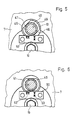
- a hexagon head 45 for a socket wrench is provided on the control shaft 44, with which the adjusting member 28 is displaced from one end position to the other.
- this socket wrench 46 has a design which enables the socket wrench to be inserted and removed from the hexagon head 45 acting as an actuating member on the control shaft 44 only in the set end positions of the adjusting member 28.
- the socket wrench has, in a manner known per se, two mutually parallel flats 47 and 48 on a flange edge 49 on two diametrically opposite sides, which engages behind a securing plate 50 which is fastened to the support disk 7.
- FIG. 6 shows a position of the socket wrench in which removal from the hexagon head 45 is possible and which corresponds to an end position of the adjusting member 28.
- FIG. 5 shows any intermediate position in which the flange edge 49 engages behind the securing plate 50 so that the socket wrench 46 cannot be removed from the hexagon 45 on the selector shaft 44.
- the hexagon 45 has a mark 51 on its front side, while on the securing plate 50 different symbols 52 and 53 for face printing as well as for face and reverse printing are attached, the associated end position of the adjusting member 28 the mark 51 in connection with the corresponding symbol.
Landscapes
- Engineering & Computer Science (AREA)
- Mechanical Engineering (AREA)
- Supply, Installation And Extraction Of Printed Sheets Or Plates (AREA)
- Transmission Devices (AREA)
Applications Claiming Priority (2)
| Application Number | Priority Date | Filing Date | Title |
|---|---|---|---|
| DE3814831 | 1988-05-02 | ||
| DE3814831A DE3814831C1 (fr) | 1988-05-02 | 1988-05-02 |
Publications (3)
| Publication Number | Publication Date |
|---|---|
| EP0340452A2 true EP0340452A2 (fr) | 1989-11-08 |
| EP0340452A3 EP0340452A3 (en) | 1990-10-31 |
| EP0340452B1 EP0340452B1 (fr) | 1994-01-26 |
Family
ID=6353376
Family Applications (1)
| Application Number | Title | Priority Date | Filing Date |
|---|---|---|---|
| EP89105685A Expired - Lifetime EP0340452B1 (fr) | 1988-05-02 | 1989-03-31 | Dispositif de réglage en rotation d'un cylindre d'un dispositif de retournement et dispositif de déplacement axial d'un élément de réglage pour le changement de la position des pinces de ce cylindre dans une rotative d'impression de feuilles |
Country Status (7)
| Country | Link |
|---|---|
| US (1) | US5031531A (fr) |
| EP (1) | EP0340452B1 (fr) |
| JP (1) | JPH0653412B2 (fr) |
| CN (1) | CN1010758B (fr) |
| AU (1) | AU605420B2 (fr) |
| CA (1) | CA1324160C (fr) |
| DE (2) | DE3814831C1 (fr) |
Families Citing this family (20)
| Publication number | Priority date | Publication date | Assignee | Title |
|---|---|---|---|---|
| DE3911609A1 (de) * | 1989-04-08 | 1990-10-11 | Heidelberger Druckmasch Ag | Bogenrotationsdruckmaschine mit mehreren druckwerken zum schoendruck und schoen- und widerdruck |
| DE3911630A1 (de) * | 1989-04-10 | 1990-10-11 | Heidelberger Druckmasch Ag | Vorrichtung zur formatverstellung an bogenfuehrungstrommeln einer druckmaschine |
| DE4004352C1 (fr) * | 1990-02-13 | 1991-06-06 | Heidelberger Druckmaschinen Ag, 6900 Heidelberg, De | |
| DE4131273C1 (fr) * | 1991-09-20 | 1992-12-10 | Heidelberger Druckmaschinen Ag, 6900 Heidelberg, De | |
| DE4141817C2 (de) * | 1991-12-18 | 1993-10-07 | Roland Man Druckmasch | Einrichtung zur Getriebezugtrennung |
| FR2693946B1 (fr) * | 1992-07-15 | 1995-03-31 | Heidelberger Druckmasch Ag | Procédé et dispositif de mise en marche/arrêt du retournement des feuilles et d'ajustement du format dans le transport de feuilles à travers une machine d'impression. |
| DE4223189C3 (de) * | 1992-07-15 | 2003-04-03 | Heidelberger Druckmasch Ag | Vorrichtung zur ferngesteuerten Betätigung von Klemmorganen einer Wendeeinrichtung |
| DE4223190C2 (de) * | 1992-07-15 | 1995-12-07 | Heidelberger Druckmasch Ag | Vorrichtung zum An- und Abstellen der Bogenwendung bei der Förderung von Bogen durch eine Druckmaschine |
| DE4322477C2 (de) * | 1992-07-15 | 1995-12-21 | Heidelberger Druckmasch Ag | Verfahren und Einrichtung zum An- und Abstellen der Bogenwendung und zur Formateinstellung bei der Förderung von Bogen durch eine Druckmaschine |
| JP3235070B2 (ja) * | 1993-07-05 | 2001-12-04 | 株式会社小森コーポレーション | 反転機構付枚葉輪転印刷機の印刷切替装置 |
| JP2602137Y2 (ja) * | 1993-11-08 | 1999-12-27 | 株式会社小森コーポレーション | 反転機構付枚葉輪転印刷機の印刷切替装置 |
| DE4401684C2 (de) * | 1994-01-21 | 1998-04-09 | Heidelberger Druckmasch Ag | Verstelleinrichtung für eine Druckmaschine |
| JP4220581B2 (ja) * | 1995-11-15 | 2009-02-04 | ハイデルベルガー ドルツクマシーネン アクチエンゲゼルシヤフト | 印刷機における反転装置の二重歯車 |
| DE19928960A1 (de) * | 1999-06-24 | 2000-12-28 | Volkswagen Ag | Zahnradtrieb |
| JP3524471B2 (ja) * | 2000-05-16 | 2004-05-10 | リョービ株式会社 | 両面印刷と片面印刷が切替可能な枚葉印刷機 |
| JP4414180B2 (ja) * | 2003-09-18 | 2010-02-10 | 株式会社小森コーポレーション | 胴装置 |
| US7412925B2 (en) * | 2004-10-04 | 2008-08-19 | Heidelberger Druckmaschinen Ag | Device for changing over gripper control in a turning configuration of a sheet-processing machine |
| JP5513781B2 (ja) * | 2009-06-15 | 2014-06-04 | 株式会社小森コーポレーション | 搬送胴の爪台高さ調節装置 |
| CN103522734B (zh) * | 2013-10-22 | 2016-03-16 | 太仓东能环保设备有限公司 | 一种方便纵横向旋转的印刷机 |
| FI125063B (fi) * | 2013-12-05 | 2015-05-15 | Metso Minerals Inc | Kiristyselin, kiristyslaite, leukamurskain, mineraalimateriaalin prosessointilaitos ja menetelmä kulutusosan kireyden säätämiseksi |
Citations (2)
| Publication number | Priority date | Publication date | Assignee | Title |
|---|---|---|---|---|
| DE2620392B1 (de) * | 1976-05-08 | 1977-09-01 | Heidelberger Druckmasch Ag | Einrichtung zum absichern einer druckmaschine fuer schoen- und widerdruck |
| DE3611325A1 (de) * | 1986-04-04 | 1987-10-08 | Heidelberger Druckmasch Ag | Vorrichtung zur verstellung der relativen drehlage zwischen einem zahnrad und einem mit diesem gleichachsig gelagerten zahnkranz |
-
1988
- 1988-05-02 DE DE3814831A patent/DE3814831C1/de not_active Expired
-
1989
- 1989-03-28 CA CA000594888A patent/CA1324160C/fr not_active Expired - Fee Related
- 1989-03-31 EP EP89105685A patent/EP0340452B1/fr not_active Expired - Lifetime
- 1989-03-31 DE DE89105685T patent/DE58906799D1/de not_active Expired - Fee Related
- 1989-04-21 AU AU33281/89A patent/AU605420B2/en not_active Ceased
- 1989-04-30 CN CN87103991A patent/CN1010758B/zh not_active Expired
- 1989-05-01 JP JP1109231A patent/JPH0653412B2/ja not_active Expired - Lifetime
- 1989-05-02 US US07/346,570 patent/US5031531A/en not_active Expired - Lifetime
Patent Citations (2)
| Publication number | Priority date | Publication date | Assignee | Title |
|---|---|---|---|---|
| DE2620392B1 (de) * | 1976-05-08 | 1977-09-01 | Heidelberger Druckmasch Ag | Einrichtung zum absichern einer druckmaschine fuer schoen- und widerdruck |
| DE3611325A1 (de) * | 1986-04-04 | 1987-10-08 | Heidelberger Druckmasch Ag | Vorrichtung zur verstellung der relativen drehlage zwischen einem zahnrad und einem mit diesem gleichachsig gelagerten zahnkranz |
Also Published As
| Publication number | Publication date |
|---|---|
| EP0340452B1 (fr) | 1994-01-26 |
| EP0340452A3 (en) | 1990-10-31 |
| DE58906799D1 (de) | 1994-03-10 |
| JPH0653412B2 (ja) | 1994-07-20 |
| JPH01317770A (ja) | 1989-12-22 |
| US5031531A (en) | 1991-07-16 |
| AU3328189A (en) | 1989-11-02 |
| DE3814831C1 (fr) | 1989-10-26 |
| CN1010758B (zh) | 1990-12-12 |
| CA1324160C (fr) | 1993-11-09 |
| AU605420B2 (en) | 1991-01-10 |
| CN1037484A (zh) | 1989-11-29 |
Similar Documents
| Publication | Publication Date | Title |
|---|---|---|
| DE3814831C1 (fr) | ||
| DD151134A1 (de) | Antrieb fuer funktionsgruppen in bogenfuehrungszylindern von druckmaschinen | |
| DE8319431U1 (de) | Vorrichtung zur umstellung auf wahlweisen schoendruck oder schoen- und widerdruck einer zwischen den einzelnen druckwerken einer bogenrotationsdruckmaschine angeordneten wendeeinrichtung | |
| EP0425936B1 (fr) | Dispositif pour le repérage, la fixation et la tension rapides de plaques d'impression | |
| DE2102412C3 (de) | Verstellvorrichtung an Kurbelwellenschleifmaschinen zum Ausrichten der zu schleifenden Kurbelzapfen | |
| DE2902421C2 (fr) | ||
| CH619629A5 (fr) | ||
| EP0377860B1 (fr) | Tambour de transfert de feuilles pour machines à imprimer pour l'impression sur le premier côté ou en retiration | |
| DE4004352C1 (fr) | ||
| DE4131273C1 (fr) | ||
| EP0069388B1 (fr) | Support de cylindres d'impression ou similaires, avec dispositif de réglage du repèrage latéral | |
| DE2901236A1 (de) | Vorrichtung zum verstellen des antriebes an bogenrotationsdruckmaschinen fuer wahlweisen schoen- oder schoen- und widerdruck | |
| EP2103367A1 (fr) | Dispositif de serrage pour objets, par exemple pour des pièces usinées devant être traitées | |
| DE4111636C1 (fr) | ||
| EP0377857B1 (fr) | Dispositif électrique de sécurité d'un système d'accouplement de tambour de transfert de feuilles dans une presse | |
| DE4324746C2 (de) | Einrichtung zum Umstellen eines Sauger- und Greifersystems | |
| DE898839C (de) | Einrichtung und Verfahren zur willkuerlichen Beseitigung und Einschaltung des toten Ganges in Spindelantrieben | |
| EP0786338A1 (fr) | Dispositif pour la mise en pression et hors pression d'un cylindre | |
| DE4208474A1 (de) | Handrad-stellvorrichtung fuer druckmaschinen | |
| EP1256447A2 (fr) | Tambour d'accumulation dans les dispositifs de retournement des machines à imprimer | |
| DE102004045098B4 (de) | Vorrichtung zur fernsteuerbaren Betätigung von Klemmelementen | |
| DD226518A1 (de) | Einrichtung zur betaetigung eines endschalters | |
| DE1577212C (de) | Exzenterpresse mit Hubverstellung | |
| DE3541473A1 (de) | Einrichtung zum betaetigen von schaltwellen in bogenfuehrungszylindern | |
| DD232673A1 (de) | Einrichtung zur umstellung von steuerkurven fuer wahlweise schoen- oder schoen- und widerdruck |
Legal Events
| Date | Code | Title | Description |
|---|---|---|---|
| PUAI | Public reference made under article 153(3) epc to a published international application that has entered the european phase |
Free format text: ORIGINAL CODE: 0009012 |
|
| 17P | Request for examination filed |
Effective date: 19890331 |
|
| AK | Designated contracting states |
Kind code of ref document: A2 Designated state(s): CH DE FR GB IT LI SE |
|
| PUAL | Search report despatched |
Free format text: ORIGINAL CODE: 0009013 |
|
| AK | Designated contracting states |
Kind code of ref document: A3 Designated state(s): CH DE FR GB IT LI SE |
|
| 17Q | First examination report despatched |
Effective date: 19920810 |
|
| GRAA | (expected) grant |
Free format text: ORIGINAL CODE: 0009210 |
|
| AK | Designated contracting states |
Kind code of ref document: B1 Designated state(s): CH DE FR GB IT LI SE |
|
| REF | Corresponds to: |
Ref document number: 58906799 Country of ref document: DE Date of ref document: 19940310 |
|
| ET | Fr: translation filed | ||
| GBT | Gb: translation of ep patent filed (gb section 77(6)(a)/1977) |
Effective date: 19940316 |
|
| ITF | It: translation for a ep patent filed | ||
| PLBE | No opposition filed within time limit |
Free format text: ORIGINAL CODE: 0009261 |
|
| STAA | Information on the status of an ep patent application or granted ep patent |
Free format text: STATUS: NO OPPOSITION FILED WITHIN TIME LIMIT |
|
| 26N | No opposition filed | ||
| EAL | Se: european patent in force in sweden |
Ref document number: 89105685.5 |
|
| PGFP | Annual fee paid to national office [announced via postgrant information from national office to epo] |
Ref country code: SE Payment date: 19960304 Year of fee payment: 8 |
|
| PG25 | Lapsed in a contracting state [announced via postgrant information from national office to epo] |
Ref country code: SE Effective date: 19970401 |
|
| EUG | Se: european patent has lapsed |
Ref document number: 89105685.5 |
|
| PGFP | Annual fee paid to national office [announced via postgrant information from national office to epo] |
Ref country code: CH Payment date: 19990331 Year of fee payment: 11 |
|
| PG25 | Lapsed in a contracting state [announced via postgrant information from national office to epo] |
Ref country code: LI Free format text: LAPSE BECAUSE OF NON-PAYMENT OF DUE FEES Effective date: 20000331 Ref country code: CH Free format text: LAPSE BECAUSE OF NON-PAYMENT OF DUE FEES Effective date: 20000331 |
|
| REG | Reference to a national code |
Ref country code: CH Ref legal event code: PL |
|
| PGFP | Annual fee paid to national office [announced via postgrant information from national office to epo] |
Ref country code: GB Payment date: 20010227 Year of fee payment: 13 |
|
| PGFP | Annual fee paid to national office [announced via postgrant information from national office to epo] |
Ref country code: FR Payment date: 20010321 Year of fee payment: 13 |
|
| REG | Reference to a national code |
Ref country code: GB Ref legal event code: IF02 |
|
| PG25 | Lapsed in a contracting state [announced via postgrant information from national office to epo] |
Ref country code: GB Free format text: LAPSE BECAUSE OF NON-PAYMENT OF DUE FEES Effective date: 20020331 |
|
| GBPC | Gb: european patent ceased through non-payment of renewal fee |
Effective date: 20020331 |
|
| PG25 | Lapsed in a contracting state [announced via postgrant information from national office to epo] |
Ref country code: FR Free format text: LAPSE BECAUSE OF NON-PAYMENT OF DUE FEES Effective date: 20021129 |
|
| REG | Reference to a national code |
Ref country code: FR Ref legal event code: ST |
|
| PG25 | Lapsed in a contracting state [announced via postgrant information from national office to epo] |
Ref country code: IT Free format text: LAPSE BECAUSE OF NON-PAYMENT OF DUE FEES;WARNING: LAPSES OF ITALIAN PATENTS WITH EFFECTIVE DATE BEFORE 2007 MAY HAVE OCCURRED AT ANY TIME BEFORE 2007. THE CORRECT EFFECTIVE DATE MAY BE DIFFERENT FROM THE ONE RECORDED. Effective date: 20050331 |
|
| PGFP | Annual fee paid to national office [announced via postgrant information from national office to epo] |
Ref country code: DE Payment date: 20070326 Year of fee payment: 19 |
|
| PG25 | Lapsed in a contracting state [announced via postgrant information from national office to epo] |
Ref country code: DE Free format text: LAPSE BECAUSE OF NON-PAYMENT OF DUE FEES Effective date: 20081001 |