EP0339645B1 - Device for reading bar codes on photographic film - Google Patents
Device for reading bar codes on photographic film Download PDFInfo
- Publication number
- EP0339645B1 EP0339645B1 EP19890107677 EP89107677A EP0339645B1 EP 0339645 B1 EP0339645 B1 EP 0339645B1 EP 19890107677 EP19890107677 EP 19890107677 EP 89107677 A EP89107677 A EP 89107677A EP 0339645 B1 EP0339645 B1 EP 0339645B1
- Authority
- EP
- European Patent Office
- Prior art keywords
- bar code
- bar
- reading
- photographic film
- negative
- Prior art date
- Legal status (The legal status is an assumption and is not a legal conclusion. Google has not performed a legal analysis and makes no representation as to the accuracy of the status listed.)
- Expired - Lifetime
Links
Images


Classifications
-
- G—PHYSICS
- G03—PHOTOGRAPHY; CINEMATOGRAPHY; ANALOGOUS TECHNIQUES USING WAVES OTHER THAN OPTICAL WAVES; ELECTROGRAPHY; HOLOGRAPHY
- G03B—APPARATUS OR ARRANGEMENTS FOR TAKING PHOTOGRAPHS OR FOR PROJECTING OR VIEWING THEM; APPARATUS OR ARRANGEMENTS EMPLOYING ANALOGOUS TECHNIQUES USING WAVES OTHER THAN OPTICAL WAVES; ACCESSORIES THEREFOR
- G03B27/00—Photographic printing apparatus
- G03B27/32—Projection printing apparatus, e.g. enlarger, copying camera
- G03B27/52—Details
- G03B27/62—Holders for the original
- G03B27/6271—Holders for the original in enlargers
- G03B27/6285—Handling strips
-
- G—PHYSICS
- G03—PHOTOGRAPHY; CINEMATOGRAPHY; ANALOGOUS TECHNIQUES USING WAVES OTHER THAN OPTICAL WAVES; ELECTROGRAPHY; HOLOGRAPHY
- G03B—APPARATUS OR ARRANGEMENTS FOR TAKING PHOTOGRAPHS OR FOR PROJECTING OR VIEWING THEM; APPARATUS OR ARRANGEMENTS EMPLOYING ANALOGOUS TECHNIQUES USING WAVES OTHER THAN OPTICAL WAVES; ACCESSORIES THEREFOR
- G03B27/00—Photographic printing apparatus
- G03B27/32—Projection printing apparatus, e.g. enlarger, copying camera
- G03B27/46—Projection printing apparatus, e.g. enlarger, copying camera for automatic sequential copying of different originals, e.g. enlargers, roll film printers
- G03B27/462—Projection printing apparatus, e.g. enlarger, copying camera for automatic sequential copying of different originals, e.g. enlargers, roll film printers in enlargers, e.g. roll film printers
Definitions
- the present invention relates to a device for reading bar codes on a photographic film which is capable of identifying the numbers and the positions of image frames by reading the bar codes affixed to the image frames.
- a photographic film such as a negative or positive film is mounted on a negative carrier.
- This carrier together with the photographic film is disposed at a printing position in a printing apparatus body for printing.
- the long negative mounted on the negative carrier is conveyed in the longitudinal direction thereof by a conveying device mounted on the negative carrier so that the image frames can be sequentially located at the printing position for printing.
- bar codes are affixed to the individual image frames at the same positions relative to the individual image frames.
- An image frame is selected for printing by reading the bar code affixed to the image frame by a sensor, the selected image frame being automatically positioned at the printing position using a notch formed in correspondence with each of the image frames.
- the bar codes correspond to the frame numbers which are assigned to the frames in a predetermined order in the longitudinal direction of a negative. This enables the bar code corresponding to a desired frame number to be retrieved by inputting the frame number by an operator therefore, it is possible to facilitate the positioning of desired image frames even when printing of the image frames is performed discontinuously for reprinting or making additional copies.
- figures representing image frame numbers or the name of a film maker may also be provided on a negative at positions which form the same locus as that of the bar codes.
- the sensor may erroneously read the figures or the letters as bar codes. This leads to a misalignment of a desired image frame or an erroneous detection of a desired bar code.
- This problem can be solved if other symbols or figures are provided at positions at which the locus thereof does not coincide with that of the bar codes.
- it is impossible to ensure sufficient space for these symbols and figures because the portion of the negative,other than the image frames, is small.
- reference WO-A-86/03041 discloses a device for reading bar codes affixed to a recording medium including a sensing device having a plurality of separate sensors disposed transverse to the direction in which the recording material is being conveyed.
- the determination of the bar code is based on the principle that when a full bar passes, all of the sensors will respond; when a half bar passes, then only the lower half of sensors will respond; and when a blank bar passes, then there will be no response from any of the sensors.
- an object of the present invention is to provide a photographic film bar code reading device which is capable of reliably reading only the bar codes affixed to a photographic film.
- the present invention achieves its object by providing a device for reading bar codes comprising the features set out in claim 1.
- the bar code reading device includes a plurality of symbol reading means disposed transverse to the direction in which the photographic film is conveyed for reading symbols, a comparison means for comparing the results of reading performed by the plurality of symbol reading means, and a determination means for determining whether or not a symbol that has been read is a bar code on the basis of the comparison results of the comparison means.
- symbols on a photographic film are read by a plurality of symbol reading means while the photographic film is being conveyed.
- the plurality of symbol reading means are disposed transverse to the direction in which the photographic film is conveyed.
- the symbols such as bar codes are symmetrical in the longitudinal direction thereof (in the direction perpendicular to the direction in which the photographic film is conveyed). In consequence, when a suitable bar code is read, all the detection results coincide with each other.
- the determination means determines that a symbol including a figure other than a bar code is read. This prevents an image frame from being shifted when it is to be positioned, which would occur when a symbol other than a bar code is erroneously detected as a bar code.
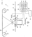
- Fig. 1 shows a photographic printing apparatus 10 to which the present invention is applied.
- light emitted from a light source 12 passes through a shutter 14 and a light diffusing cylinder 16 and reaches a negative 19 which is a photographic film.
- the negative 18 carries a plurality of image frames in the longitudinal direction thereof.
- the end portion of the negative 18 is coupled to another negative 18 having the same form by splicing tape 19. This enables a plurality of negatives to be successively conveyed.
- the negative 18 is held by a negative carrier 20.
- the negative carrier 20 has an opening 22.
- An image of the image frame located at this opening 22 is formed on a lens 24.
- the negative 18 has notches 18b formed on each image frame.
- a desired image frame can be readily located at the printing position by detecting the corresponding notch 18B by a notch detecting sensor (not shown) .
- the notches 18B are formed on the negative 18 by a notch puncher (not shown) after the development of the negative 18.
- the light that passes through the lens 24 reaches an emulsion coated surface of a sheet of printing paper 26 to cause the printing paper 26 to be exposed to the light.
- the two ends of the printing paper 26 are respectively wound around winding rollers 28 and 30. Each time one image is formed on the printing paper 26, the sheet of printing paper 26 is unwound from the roller 28 and wound around the roller 30.
- the negative carrier 20 is provided with a driving device 32 for conveying the negative 18.
- the driving device 32 is driven by a signal sent from a control device 34.
- the driving device 32 is a pulse motor which conveys the negative 18 in accordance with the number of pulses supplied from the control device 34. In this embodiment, the negative is conveyed by 0.1 mm per one pulse supplied to the pulse motor.
- the shutter 14 is also connected to the control device 34 through a driver 36 so that it can be opened for a predetermined period of time when printing is performed.
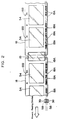
- a pair of position information detecting sensors 38 and 39 which serve as position information detecting means, are disposed on the upstream side of the negative carrier in order to read bar codes 18A (see Fig. 2) provided on the negative 18 while the negative 18 is being conveyed.
- the position information detecting sensors 38 and 39 are provided in the longitudinal direction of the bar code 18A so that the presence or non-presence of a bar code 18A can be detected in the vicinity of the two longitudinal end portions of the bar code 18A.
- the data representing the bar code 18A read by the position information detecting sensors 38 and 39 is supplied to the control device 34.
- Symbols other than the bar codes 18A or characters may be provided on the negative 18 at positions which form the same locus as that of the bar codes 18A. More specifically, Arabic figures representing frame numbers may be provided on the negative in addition to the bar codes 18A. These Arabic figures may be read as bar codes by mistake 18A, causing read errors. While the bar codes 18A have the same height, the figures are not symmetrical in the vertical direction. In consequence, the control device 34 makes a determination as to whether or not the detected values of the two position information detecting sensors 38 and 39 coincide with each other, thereby preventing erroneous reading of symbols other than the bar code.
- the control device incorporates a CPU 40, a RAM 42, a ROM 44, an I/O (input/output) port 46 and a data bus and control bus that interconnect these components.
- the driver 36 for the shutter 14, the driving device 32 and the position information detecting sensors 38 and 39 are all connected to the I/O 46 through signal lines. Also, a keyboard 50 is connected to this I/O 46.
- the bar codes 18A are provided on the negative 18 at the same positions relative to individual image frames 54.
- the position information reading sensors 38 and 39 are disposed at positions which are on the locus of the bar codes 18A.
- the bar codes 18A correspond to the image frame numbers.
- the data read by the position information reading sensors 38 and 39 is passed through a data conversion circuit 56 (see Fig. 3).
- the converted data is used to recognize the frame number corresponding to the bar code 18A which is represented by the data read by the position information reading sensors 38 and 39.
- the frame number designated by the keyboard 50 can be retrieved by comparing the frame number detected on the basis of the data read by the position information reading sensors with the designated frame number.
- the frame numbers are appended in a predetermined order (for example, in the order of 1, 1A, 2, 2A, 3, 3A ).
- the frame numbers are stored in the RAM 42 of the control device 34.
- the position information detecting sensor 38 (39) has four detecting units 58A, 58B, 58C and 58D and the data conversion circuit 56, as shown in Fig. 3.
- the bars that form a bar code 18A fall into two types: a wide one and a narrow one.
- the distance required for the detecting units 58A, 58B, 58C and 58D to be disposed is equivalent to the width of the wide bar.
- the bar code which has the narrower width equals to the space required for the two detecting units.
- the detecting unit 58A is connected to a negative input terminal of a first differential unit 60.
- the detecting unit 58B is connected to a positive input terminal of the first differential unit 60 and to a negative input terminal of a second differential unit 62.
- the detecting unit 58C is connected to a positive input terminal of the second differential unit 62 and to a negative input terminal of a third differential unit 64.
- the detecting unit 58D is connected to a positive input terminal of the third differential unit 64.
- the output of the first differential unit 60 is connected to a positive input terminal of a first comparator 66 and to a negative input terminal of a second comparator 68.
- the output of the second differential unit 62 is connected to a positive input terminal of a third comparator 70 and a negative input terminal of a fourth comparator 72.
- the output of the third differential unit 64 is connected to a positive input terminal of a fifth comparator 74 and to a negative input terminal of a sixth comparator 76.
- a voltage of +V (which is 0.66 V) is applied to the negative input terminals of the first, third and fifth comparators 66, 70 and 74, and a voltage of -V (which is -0.66 V) is applied to the positive input terminals of the second, fourth and sixth comparators 68, 72 and 76.
- data representing a value determined by a difference in the outputs of the adjacent detecting units in accordance with an absolute value is input to the I/O 46 of the control device 34.
- the first and second comparators output high level signals when
- the detected data representing the output differences is supplied to the control device 34.
- the control device 34 determines, in response to the differences in the outputs of the detecting units 58A, 58B, 58C and 58D,whether a white portion or a black portion of a bar code 18A is passing through the detection position. It also determines the width of a bar which is passing through the detection position (whether a wide bar or a narrow bar is passing). The determination procedure will be described below with reference to Fig. 4.
- the outputs of the detecting units 58A, 58B, 58C and 58D are respectively simplified as A, B, C and D.
- the control device 34 determines that A ⁇ B > C > D, as shown in Fig. 4 (C). This means that the white bar passed through the detecting unit 58A and that the detecting units 58B and 58C are together detecting the white bar. In consequence, the control device recognizes that the detected bar is a narrow white bar.
- A, B, C and D are shifting in the forward direction from the state shown in Fig. 4 (C), and the control device confirms that the negative is moving in the forward direction.
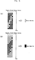
- Fig. 5 shows changes in the outputs of the detecting units 58A, 58B, 58C and 58D which occur as a bar code 18A passes through the detecting units. More specifically, Fig. 5(A) shows changes in the outputs of the detecting units 58A, 58B, 58C and 58D which occur as a narrow white bar code passes through the detecting units. Fig. 5(B) shows changes in the outputs of the detecting units 58A, 58B, 58C and 58D which occur as a wide black bar passes the detecting units. As can be seen in Figs. 5(A) and 5(B), it is thus possible to check whether the negative is stopped or fed in the reverse direction.
- the control device 34 sequentially inserts a combination of bars (13 bars in this embodiment) that form a bar code 18A in a table or a buffer) of the RAM 42.
- the detected bar is always inserted from a first portion of the table (from the right side of the table, as viewed in Fig. 6), the already inserted bars being individually shifted to the left as a newly detected bar is inserted in the table.
- the bars inserted in the table are extracted from the right side of the table.
- the individual bars are shifted to the right in the table, as a bar is extracted from the table.
- control device 34 operates a number of pulses that are applied to the pulse motor in order to obtain a bar code reading position corresponding to frame number 0 (a reference position) by using the frame number corresponding to the read bar code 18A and the number of pulses which has been applied to the pulse motor in order to position that bar code at the bar code detected position.
- the above-described calculation is performed by reading two consecutive different bar codes in the longitudinal direction of the negative when the negative is being conveyed. If the number of pulses required for the reference position which is calculated on the basis of reading of a preceding bar code of the consecutive different bar codes, does not coincide with that for the reference position, which is calculated on the basis of reading a subsequent bar code of the consecutive different bar codes, the number of pulses corresponding to the reading of the preceding bar code is cancelled. In addition, the number of pulses for the reference position which is calculated on the basis of reading of another bar code following the reading of the subsequent bar code is obtained. The obtained number of pulses is then compared with the number of pulses calculated on the basis of the reading of the subsequent bar code. This calculation and comparison are repeated until the number of pulses required for the reference position, which are calculated on the basis of the readings of two consecutive different bar codes become identical. This enables an accurate number of pulses required for the reference position to be obtained.
- predetermined number of pulses per pitch are respectively made to represent the bar code positions with the -reference position serving as a starting point. Further, since the frame numbers are appended in a predetermined order, it is possible to determine whether or not the reading is performed accurately by comparing the frame number calculated using the calculated number of pulses with the actually read frame number.
- the position information detection unit 58 also detects the connected portion of the negatives 18. More specifically, the control device 34 determines that the beginning of a new negative 18 has been detected when the position information detecting unit 58 detects the splicing tape 19 that connects the negatives 18. The control device then updates the frame numbers stored in the RAM 42 each time the splicing tape 19 is detected so as to newly define the number of pulses required for the reference position.
- Figs. 7 to 9 are flowcharts of the operation of this embodiment.
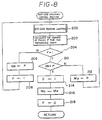
- variable I is set to 0, and flags F and G are reset, i.e., become 0, in step 100.
- a negative 18 is set in step 102, and the frame numbers representing the image frames on which printing is to be performed are then designated in step 104.
- the frame numbers designated may be successive or intermittent.
- step 106 an operator switches on a start switch or the like to start the printing operation in step 106.
- the driving device 32 is thereby driven (the stepping motor is started) in step 107.
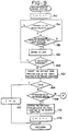
- step 108 it is determined in step 108 whether or not the splicing tape 19 is detected. If the answer is no, the control device determines that a subsequent negative 18 is not yet supplied, and the processing goes on to step 110 where it is determined whether or not flag G is set. If the answer is no, the control device determines that the bar code positions and the number of pulses for the stepping motor are not yet collated with each other (the number of pulses required for the reference position is not yet set). Processing then proceeds to step 112 where the bar code checking control routine is executed. This bar code checking control routine will be described later in detail.
- step 108 If the splicing tape 19 is detected in step 108, the processing goes to step 109 where the flag G is reset. The processing then goes on to step 112. Further, if it is determined in step 110 that the flag G is set, since the bar codes and the numbers of pulses are collated with each other (the number of pulses required for the reference point is set), the processing skips step 112 and goes on to step 114.
- step 114 the negative is conveyed in accordance with the number of pulses required for the designated frame number position.
- the designated image frame is then located at the printing position in step 116. Once the designated image frame has been located at the printing position, printing is processed in step 118. Next, it is determined in step 120 whether or not the printing of the designated image frames is completed. If the answer is no, the processing returns to step 107. In this way, the designated image frames are sequentially located at the printing position and printing is sequentially performed on the image frames located at the printing position. Once printing has been performed on all the designared image frames, this control routine is complete.
- step 200 the bar code reading control subroutine which is described later is executed in step 200.
- the number of pulses P required for the reference point (the frame number 0 position in this embodiment) is calculated on the basis of this bar code using the above-described equation in step 202.
- step 204 If it is determined in step 204 that 1 is set in flag F, since the holding memory M R stores the calculated value P, the calculated value P is compared with the value in the holding memory M R in step 210. If M R P, the processing goes to step 212 where the newly calculated value P is written in the holding memory M R (the value in the holding memory M R is updated), and the processing then returns to step 200 so as to exccute steps 202, 204, 210 and 212.
- step 216 the value stored in the holding memory M R is written in the defined memory M D .
- the flag F is reset in step 218, thereby completing this bar code checking control subroutine and returning to step 114.
- variable I is incremented in step 150, and it is then determined in step 154 whether or not there are changes in the outputs of the detecting units 58A, 58B, 58C and 58D while the negative 18 is being conveyed. If the answer is no, the processing executed in step 154 is repeated. If the answer is yes, the processing proceeds to step 156 where it is determined whether or not the outputs of the detecting units 58A, 58B, 58C and 58D of the detector located at one longitudinal end portion of the bar code 18A is identical with those of the detecting units of the detector located at the other longitudinal end portion of the bar code 18A.
- the processing returns to step 154.
- figures and symbols other than the bar codes 18A may be present on the locus formed on the negative 18 by the detecting units 58A, 58B, 58C, and 58D.
- the bar codes 18A are read in the vicinity of both the two longitudinal end portions thereof (see the dot-dashed line and the dot-dot-dashed line in Fig. 2). This prevents the control device from erroneously recognizing figures as bar codes 18A, thereby preventing erroneous detection.
- step 156 If it is determined in step 156 that the outputs of the upper and lower detecting units are identical, the control device determines that the detected symbol is a bar that constitutes a bar code, and therefore defines the detected symbol as an Ith bar of a bar code in step 158. If such determination is impossible this is recognized in step 160, processing returns to step 154. If the Ith bar is defined in step 158, this is recognized in step 160, and the defined bar is then inserted into the table in the RAM 42 from one side thereof (the right side as viewed in Fig. 6) in step 162. In that case, if a row of bars have been already set in the table, they are sequentially shifted in the forward direction.
- step 164 it is determined in step 164 whether or not the variable I is 13, which is the upper limit of a bar code. If it is determined that I ⁇ 13, the control device determines that all the bars that constitute one bar code 18A have been read. Thereafter, the variable I is reset to 0 in step 166, and then the processing returns to the main routine.
- step 164 the control device determines that reading of one bar code is not yet completed, and the processing goes to step 168 where it is determined whether or not the negative 18 is being fed in the reverse direction. If the negative 18 is not being fed in the reverse direction, the processing goes to step 108 of the main routine. If it is, the processing proceeds to step 170 where a number of bars corresponding to the amount of reverse feeding are moved out of the table from one side thereof (the right side thereof as viewed in Fig. 6). At that time, the remaining bars are sequentially shifted in the table in the reverse direction. Once the step 170 has been executed, variable I is decremented in step 172, and processing then returns to step 202.
- the bars that constitute one bar code are detected one by one from the changes in the outputs of the detecting units 58A, 58B, 58C and 58D.
- a number of bars corresponding to the amount of reverse feeding are cancelled, thereby ensuring a reliable bar code reading operation which eliminates any reading errors.
- an image frame determined in accordance with the number of pulses from the pulse motor can be confirmed.
- a frame number representing an erroneously read image frame can be estimated. In consequence, it is possible to smoothly perform the printing operation in a designated order without temporarily interrupting the printing operation and without cancelling the printing operation to be performed on the image frames corresponding to erroneously read bar codes.
- the connected portion of the adjacent negatives can be recognized by detecting the splicing tape 19, thereby eliminating the possibility of the erroneous recognition of the image frames.
- the position information detecting sensors are disposed in the vicinity of the two longitudinal end portions of a bar code, it is possible to prevent erroneous recognition of the figures or the like that moves on the same locus as that of the bar code 18A, thus improving the workability.
- the bar code reading device is capable of reliably reading only the bar codes affixed to a photographic film.
Landscapes
- Physics & Mathematics (AREA)
- General Physics & Mathematics (AREA)
- Projection-Type Copiers In General (AREA)
- Light Sources And Details Of Projection-Printing Devices (AREA)
Applications Claiming Priority (2)
| Application Number | Priority Date | Filing Date | Title |
|---|---|---|---|
| JP63106104A JP2505528B2 (ja) | 1988-04-28 | 1988-04-28 | 写真フイルムのバ―コ―ド読取装置 |
| JP106104/88 | 1988-04-28 |
Publications (3)
| Publication Number | Publication Date |
|---|---|
| EP0339645A2 EP0339645A2 (en) | 1989-11-02 |
| EP0339645A3 EP0339645A3 (en) | 1991-07-31 |
| EP0339645B1 true EP0339645B1 (en) | 1996-09-04 |
Family
ID=14425196
Family Applications (1)
| Application Number | Title | Priority Date | Filing Date |
|---|---|---|---|
| EP19890107677 Expired - Lifetime EP0339645B1 (en) | 1988-04-28 | 1989-04-27 | Device for reading bar codes on photographic film |
Country Status (3)
| Country | Link |
|---|---|
| EP (1) | EP0339645B1 (ja) |
| JP (1) | JP2505528B2 (ja) |
| DE (1) | DE68927067T2 (ja) |
Families Citing this family (1)
| Publication number | Priority date | Publication date | Assignee | Title |
|---|---|---|---|---|
| GB9004571D0 (en) * | 1990-03-01 | 1990-04-25 | Kodak Ltd | Improvements in and relating to film frame identification |
Family Cites Families (15)
| Publication number | Priority date | Publication date | Assignee | Title |
|---|---|---|---|---|
| JPS5314331B2 (ja) * | 1972-09-25 | 1978-05-17 | ||
| JPS5330616B2 (ja) * | 1974-05-29 | 1978-08-28 | ||
| JPS5242333A (en) * | 1975-09-30 | 1977-04-01 | Matsushita Electric Ind Co Ltd | Bar code reader |
| JPS5263625A (en) * | 1975-11-19 | 1977-05-26 | Nippon Denso Co Ltd | Bar code reader |
| JPS5471541A (en) * | 1977-11-18 | 1979-06-08 | Nippon Electric Ind | System for retrieving negative film |
| US4219737A (en) * | 1978-12-18 | 1980-08-26 | Visual Systems Corporation | Self regulating microfilm frame detection circuit |
| JPS56128933A (en) * | 1980-03-14 | 1981-10-08 | Fuji Color Service:Kk | Display method for film frame number to print |
| JPS57126314A (en) * | 1981-01-30 | 1982-08-06 | Sumitomo Metal Ind Ltd | Tracking method of pipe or bar material |
| JPS60195680A (ja) * | 1984-03-16 | 1985-10-04 | Fuji Photo Film Co Ltd | バ−コ−ド読取装置 |
| US4641018A (en) * | 1984-11-09 | 1987-02-03 | Ncr Corporation | Bar code and reading and decoding device |
| JPS61254942A (ja) * | 1985-05-07 | 1986-11-12 | Norio Iwasaki | 駒番号を記録する写真プリンタ−及びフイルム |
| JPS6252542A (ja) * | 1985-08-31 | 1987-03-07 | Minolta Camera Co Ltd | マイクロフイルムのプリンタ− |
| JPS6285234A (ja) * | 1985-10-09 | 1987-04-18 | Fuji Photo Film Co Ltd | 写真焼付け用ノツチヤ−・パンチヤ− |
| US4704519A (en) * | 1986-06-19 | 1987-11-03 | Emhart Industries, Inc. | Selective code reader |
| JPH01263637A (ja) * | 1988-04-15 | 1989-10-20 | Fuji Photo Film Co Ltd | 写真フイルムの位置情報読取装置 |
-
1988
- 1988-04-28 JP JP63106104A patent/JP2505528B2/ja not_active Expired - Lifetime
-
1989
- 1989-04-27 EP EP19890107677 patent/EP0339645B1/en not_active Expired - Lifetime
- 1989-04-27 DE DE1989627067 patent/DE68927067T2/de not_active Expired - Lifetime
Also Published As
| Publication number | Publication date |
|---|---|
| DE68927067D1 (de) | 1996-10-10 |
| EP0339645A3 (en) | 1991-07-31 |
| EP0339645A2 (en) | 1989-11-02 |
| JP2505528B2 (ja) | 1996-06-12 |
| DE68927067T2 (de) | 1997-01-16 |
| JPH01277226A (ja) | 1989-11-07 |
Similar Documents
| Publication | Publication Date | Title |
|---|---|---|
| US5564846A (en) | Printer with sheet positioning marks control | |
| US5264683A (en) | Method of collating photographic prints with photographic film | |
| EP0293887B1 (en) | Photographic printing method and apparatus therefor | |
| EP0320880B1 (en) | Method of identifying frame numbers of photographic film | |
| US4693591A (en) | Microfilm and microfilm printer | |
| US4961086A (en) | Device for reading positional information on photographic films | |
| US6196098B1 (en) | Paper cutter for photographic processing system | |
| US5268563A (en) | Device for reading bar codes on photographic film | |
| JP2568346B2 (ja) | 感光性材料を処理する装置 | |
| US5212367A (en) | Method of reading positional information on photographic film | |
| US5336873A (en) | Photographic film having frame number bar codes | |
| EP0339645B1 (en) | Device for reading bar codes on photographic film | |
| US4728996A (en) | Photographic printing method | |
| US5157437A (en) | Apparatus and method for checking coincidence between frame specification data and an actual frame of an auto-printer | |
| US5179266A (en) | Photographic film and method of identifying frame numbers of photographic film | |
| EP0333092B1 (en) | Photographic printing method | |
| EP0339643B1 (en) | A method of specifying frame number | |
| US5248887A (en) | Method of and apparatus for determining the orientation of film | |
| JPS63305337A (ja) | 写真焼付装置 | |
| EP0301397B2 (en) | Collating device | |
| US4419009A (en) | Data converting method for reordered prints | |
| JPH0685042B2 (ja) | 写真焼付方法 | |
| US5604564A (en) | Process and device for preparing film strips for subsequent orders | |
| JPS62264983A (ja) | 伝票印字装置 | |
| JPH0620084A (ja) | バーコード読取式伝票印刷機 |
Legal Events
| Date | Code | Title | Description |
|---|---|---|---|
| PUAI | Public reference made under article 153(3) epc to a published international application that has entered the european phase |
Free format text: ORIGINAL CODE: 0009012 |
|
| AK | Designated contracting states |
Kind code of ref document: A2 Designated state(s): DE FR GB |
|
| PUAL | Search report despatched |
Free format text: ORIGINAL CODE: 0009013 |
|
| AK | Designated contracting states |
Kind code of ref document: A3 Designated state(s): DE FR GB |
|
| 17P | Request for examination filed |
Effective date: 19920108 |
|
| 17Q | First examination report despatched |
Effective date: 19930729 |
|
| GRAH | Despatch of communication of intention to grant a patent |
Free format text: ORIGINAL CODE: EPIDOS IGRA |
|
| GRAH | Despatch of communication of intention to grant a patent |
Free format text: ORIGINAL CODE: EPIDOS IGRA |
|
| GRAA | (expected) grant |
Free format text: ORIGINAL CODE: 0009210 |
|
| AK | Designated contracting states |
Kind code of ref document: B1 Designated state(s): DE FR GB |
|
| REF | Corresponds to: |
Ref document number: 68927067 Country of ref document: DE Date of ref document: 19961010 |
|
| ET | Fr: translation filed | ||
| PLBE | No opposition filed within time limit |
Free format text: ORIGINAL CODE: 0009261 |
|
| STAA | Information on the status of an ep patent application or granted ep patent |
Free format text: STATUS: NO OPPOSITION FILED WITHIN TIME LIMIT |
|
| 26N | No opposition filed | ||
| REG | Reference to a national code |
Ref country code: GB Ref legal event code: IF02 |
|
| REG | Reference to a national code |
Ref country code: GB Ref legal event code: 732E |
|
| REG | Reference to a national code |
Ref country code: FR Ref legal event code: TP Ref country code: FR Ref legal event code: CD |
|
| PGFP | Annual fee paid to national office [announced via postgrant information from national office to epo] |
Ref country code: FR Payment date: 20080312 Year of fee payment: 20 Ref country code: DE Payment date: 20080502 Year of fee payment: 20 |
|
| PGFP | Annual fee paid to national office [announced via postgrant information from national office to epo] |
Ref country code: GB Payment date: 20080430 Year of fee payment: 20 |
|
| REG | Reference to a national code |
Ref country code: GB Ref legal event code: PE20 Expiry date: 20090426 |
|
| PG25 | Lapsed in a contracting state [announced via postgrant information from national office to epo] |
Ref country code: GB Free format text: LAPSE BECAUSE OF EXPIRATION OF PROTECTION Effective date: 20090426 |