EP0339226B1 - Sammel- oder Fangvorrichtung mit Füllstandsanzeige für ein Garten-, Rasen- oder Landschaftspflegegerät - Google Patents
Sammel- oder Fangvorrichtung mit Füllstandsanzeige für ein Garten-, Rasen- oder Landschaftspflegegerät Download PDFInfo
- Publication number
- EP0339226B1 EP0339226B1 EP89104387A EP89104387A EP0339226B1 EP 0339226 B1 EP0339226 B1 EP 0339226B1 EP 89104387 A EP89104387 A EP 89104387A EP 89104387 A EP89104387 A EP 89104387A EP 0339226 B1 EP0339226 B1 EP 0339226B1
- Authority
- EP
- European Patent Office
- Prior art keywords
- collecting
- indicating element
- air
- means according
- catching means
- Prior art date
- Legal status (The legal status is an assumption and is not a legal conclusion. Google has not performed a legal analysis and makes no representation as to the accuracy of the status listed.)
- Expired - Lifetime
Links
- 238000012423 maintenance Methods 0.000 title claims abstract description 5
- 239000004744 fabric Substances 0.000 claims abstract description 7
- 239000000463 material Substances 0.000 claims abstract description 4
- 241001417527 Pempheridae Species 0.000 claims description 2
- 238000004026 adhesive bonding Methods 0.000 claims description 2
- 230000035699 permeability Effects 0.000 claims description 2
- 238000007789 sealing Methods 0.000 claims description 2
- 241001237160 Kallima inachus Species 0.000 claims 2
- 239000011888 foil Substances 0.000 claims 1
- 244000025254 Cannabis sativa Species 0.000 description 5
- 238000010276 construction Methods 0.000 description 1
- 238000011109 contamination Methods 0.000 description 1
- 230000001419 dependent effect Effects 0.000 description 1
- 238000001514 detection method Methods 0.000 description 1
- 230000005484 gravity Effects 0.000 description 1
- 230000001771 impaired effect Effects 0.000 description 1
- 239000002985 plastic film Substances 0.000 description 1
- 229920006255 plastic film Polymers 0.000 description 1
- 239000007787 solid Substances 0.000 description 1
- 238000011179 visual inspection Methods 0.000 description 1
Images

Classifications
-
- A—HUMAN NECESSITIES
- A01—AGRICULTURE; FORESTRY; ANIMAL HUSBANDRY; HUNTING; TRAPPING; FISHING
- A01D—HARVESTING; MOWING
- A01D43/00—Mowers combined with apparatus performing additional operations while mowing
- A01D43/06—Mowers combined with apparatus performing additional operations while mowing with means for collecting, gathering or loading mown material
- A01D43/063—Mowers combined with apparatus performing additional operations while mowing with means for collecting, gathering or loading mown material in or into a container carried by the mower; Containers therefor
- A01D43/0631—Control devices specially adapted therefor
-
- A—HUMAN NECESSITIES
- A01—AGRICULTURE; FORESTRY; ANIMAL HUSBANDRY; HUNTING; TRAPPING; FISHING
- A01D—HARVESTING; MOWING
- A01D2101/00—Lawn-mowers
-
- A—HUMAN NECESSITIES
- A01—AGRICULTURE; FORESTRY; ANIMAL HUSBANDRY; HUNTING; TRAPPING; FISHING
- A01D—HARVESTING; MOWING
- A01D34/00—Mowers; Mowing apparatus of harvesters
- A01D34/01—Mowers; Mowing apparatus of harvesters characterised by features relating to the type of cutting apparatus
- A01D34/412—Mowers; Mowing apparatus of harvesters characterised by features relating to the type of cutting apparatus having rotating cutters
- A01D34/63—Mowers; Mowing apparatus of harvesters characterised by features relating to the type of cutting apparatus having rotating cutters having cutters rotating about a vertical axis
Definitions
- the invention relates to a collecting or catching device for a garden, lawn or landscape maintenance device with a fill level indicator, the material to be collected or collected being transferred to the at least partially air-permeable collecting or catching device through the use of an air flow generated by the device and a display element deflected by the buoyancy of the air flow flowing through the collecting or catching device from the rest position is present as a level indicator.
- a collecting and catching device which provides in the rear area a compartment which is separated from the collecting space and which is separated by an air-permeable grille.
- a display element is designed as a flap which is pivotally attached to the outer part of the catching device and is used as a fill level indicator by the air flow generated.
- a disadvantage of this known embodiment is the relatively small-area display element, the function of which depends to a considerable extent on the excess pressure achieved and the function of which is impaired by friction and contamination.
- the deflection during normal function and the return to the original position is dependent on gravity and easily leads to incorrect level information, for example in hilly terrain. Beyond that it is required that the display element is attached in the rear area. However, such an attachment falsifies the result, since the rear area is filled first.
- the invention is therefore based on the object of proposing a fill level indicator for collecting or catching devices in connection with garden, lawn or landscape maintenance devices, which is simple in construction and enables early detection of the filled state.
- the display element is flat and is fastened with at least one side edge to the air-permeable outer surface of the collecting or catching device and in which the indicating element is made of a fabric that has a lower air permeability than the wall of the collecting or catching device or consists of a plastic film.
- the invention is based on the knowledge that as long as the material to be collected can still be transferred to the collecting or catching device, there is also an air stream that flows through the catching device and, due to its permeable design, emerges outside. However, if the collecting or catching device is completely filled, the ejection opening acts like a kind of valve that has been closed.
- the air can no longer flow into the collecting or catching device.
- the deflection of the display element is canceled, which shows that no further good can be picked up.
- the display element In the event of normal working conditions, i.e. as long as goods can still be transferred to the collecting or catching device, the display element is lifted off the contact surface in the manner of a flag.
- the display element is fastened to the outer surface of the collecting or catching device with two opposite side edges and the distance of the fastening points on the collecting or catching device is smaller than the elongated length of the flat indicating element, measured between those for fastening provided side edges.
- the display element stands out from the ground like a kind of sail.
- the display element is also possible for the display element to be provided between the fastening points with at least two further articulation points, the axes of which extend parallel to the side edges which are provided for fastening. This allows the amount of lift-off that is required to be normal To recognize the working state or to recognize whether the collecting or catching device is filled, be enlarged.
- the fastening points and / or the further articulation points are designed as buckling edges or film hinge points.
- the display element can be connected to the collecting or catching device by sealing, gluing, buttons, clips or a Velcro fastener. It is therefore also possible to retrofit existing existing devices without any problems.
- the display element can be assigned to one of the side surfaces, the top surface or the rear surface of the collecting or catching device.
- the assignment to the top surface is preferred. It is also proposed that the display element be arranged as close as possible to the ejection opening of the device.
- a preferred application for the collecting or catching device according to the invention are sickle lawn mowers, scarifiers, leaf vacuums or leaf sweepers with an ejection opening. Since the prerequisite is that the collecting or catching device is permeable to air, it is proposed to use it in conjunction with a collecting bag made of an air-permeable fabric or with a perforated collecting basket.
- a sickle lawn mower 1 is shown, at the rear discharge opening 3, a grass bag 2 is connected as a collecting or catching device.
- the grass catcher 2 comprises a solid base plate 4 and a wire frame, which is enclosed by a fabric that is permeable to air.
- the top surface of the collecting bag 2 is designated 5, the side surfaces 6, 6a and the rear surface 7. Furthermore, the grass catcher is provided with a handle 8.
- the flat display element 9 is shown arranged on different surfaces 5, 6, 6a, 7 of the outer circumference of the collecting bag 2.
- the preferred arrangement takes place in the area of the top surface 5, although an arrangement on the side surfaces 6, 6a or the rear surface 7 of the collecting bag 2 is also conceivable.
- the collecting bag 2 is shown in plan view in FIG.
- the flag-like or flap-like display elements 9 has two side edges 10 aligned with the longitudinal axis of the collecting bag 2 and two side edges 10a arranged perpendicularly in the plane of the collecting bag 2 and is connected to a side edge 10a by a fastening point 11 with the top surface 5.
- This side edge 10a is preferably arranged close to the ejection opening 3, at the rear of the device 1.
- the fastening point 11, which forms the side edge 10a should extend at right angles to the longitudinal axis of the collecting bag 2.
- the flat-shaped display element 9 is connected to the collecting bag 2, in particular its top surface 5, with two side edges 6, 6a via fastening points 11, 11a.
- the stretched length of the strip-shaped display element 9 is greater than the distance between the fastening points 11, 11a.
- Figure 3 shows the normal position, i.e. the position during the filling of the collecting bag 2. If the collecting bag 2 is filled, the display element 9 falls down and lies on the surface, i.e. the top surface 5 of the collecting bag 2. This position is shown in broken lines.
- FIG. 4 there are also two Fastening points 11, 11a are provided for the display element 9. It is also assigned to the top surface 5. However, further articulation points 12, 12a, 12b and 12c are provided between the two fastening points 11, 11a. Since the display element 9 is a fabric strip or a film, the articulation points 12, 12a, 12b, 12c, and the fastening points 11, 11a can be formed by sharp folding edges or film hinge points. In this way, a targeted folding and raising is achieved.
- FIG. 5 A similar design is shown in FIG. 5. However, this is not a rear view as in FIG. 4.
- the display element 9 is not arranged transversely on the top surface 5, but rather along the catch bag.
- the attachment points 11, 11a of the display element are thus offset from one another on the longitudinal axis of the collecting bag 2.
- the erected position that is the position at which filling is still taking place, is shown as a solid line, while the folded position is shown as a dashed line.
Landscapes
- Life Sciences & Earth Sciences (AREA)
- Environmental Sciences (AREA)
- Harvester Elements (AREA)
- Catching Or Destruction (AREA)
- Soil Working Implements (AREA)
Description
- Die Erfindung betrifft eine Sammel- oder Fangvorrichtung für ein Garten-, Rasen- oder Landschaftspflegegerät mit einer Füllstandsanzeige, wobei das zu sammelnde oder aufzufangende Gut durch Ausnutzung eines vom Gerät erzeugten Luftstromes durch die Auswurföffnung in den zumindest teilweise luftdurchlässige Sammel- oder Fangeinrichtung überführt wird und als Füllstandsanzeiger ein durch die Auftriebskraft des die Sammel- oder Fangvorrichtung durchströmenden Luftstromes aus der Ruhelage abgelenktes Anzeigeelement vorhanden ist.
- Aus der GB-A-1 242 515 ist eine Sammel- und Fangeinrichtung bekannt, die im rückwärtigen Bereich ein vom Sammelraum getrenntes Abteil vorsieht, das durch ein luftdurchlässiges Gitter abgetrennt ist. Ein Anzeigeelement ist als Klappe ausgebildet, welche einseitig schwenkbar am Außenteil der Fangeinrichtung angebracht ist und als Füllstandsanzeige durch den erzeugten Luftstrom verwendet wird.
- Von Nachteil bei dieser bekannten Ausführung ist das relativ kleinflächige Anzeigeelement, dessen Funktion in erheblichem Maße von dem erzielten Überdruck abhängt und deren Funktion durch Reibung und Verschmutzung beeinträchtigt wird. Die Auslenkung während der normalen Funktion und die Rückstellung in die Ursprungslage ist hierbei von der Schwerkraft abhängig und führt zum Beispiel in einem hügeligen Gelände leicht zu falschen Füllstandsinformationen. Darüber hinaus ist es erforderlich, daß das Anzeigeelement im hinteren Bereich angebracht ist. Eine solche Anbringung verfälscht jedoch das Ergebnis, da der hintere Bereich zuerst gefüllt wird.
- Im Zusammenhang mit den obengenannten Geräten ist immer wieder auf das Bedürfnis hingewiesen worden, eine Füllstandsanzeige vorzusehen.
- Für den Bediener eines solchen Gerätes ist erst dann, wenn das Gut, das eigentlich aufgenommen werden soll, auf dem Boden liegenbleibt, ein Zeichen gegeben, daß die Fangvorrichtung gefüllt ist und kein weiteres Gut mehr aufnehmen kann. Insbesondere bei Rasenmähern stellt der Bediener häufig erst nach mehreren Metern, die er zurückgelegt hat, fest, daß kein Gras mehr in die Fangvorrichtung überführt wird. Eine Sichtkontrolle ist kaum möglich.
- Der Erfindung liegt daher die Aufgabe zugrunde, einen Füllstandsanzeiger für Sammel- oder Fangvorrichtungen in Verbindung mit Garten-, Rasen- oder Landschaftspflegegeräten vorzuschlagen, der einfach im Aufbau ist und ein frühzeitiges Erkennen des gefüllten Zustandes möglich macht.
- Diese Aufgabe wird erfindungsgemäß dadurch gelöst, daß das Anzeigeelement flächig ausgebildet und mindestens mit einer Seitenkante an der luftdurchlässigen Außenfläche der Sammel- oder Fangvorrichtung befestigt ist und bei der das Anzeigeelement aus einem Gewebe, das eine geringere Luftdurchlässigkeit als die Wandung der Sammel- oder Fangvorrichtung aufweist oder aus einer Kunststoffolie besteht.
- Die Erfindung geht von der Erkenntnis aus, daß solange noch das aufzusammelnde Gut in die Sammel- oder Fangvorrichtung überführt werden kann, auch noch ein Luftstrom vorhanden ist, der die Fangeinrichtung durchströmt und aufgrund deren durchlässigen Ausbildung nach außen tritt. Ist jedoch die Sammel- oder Fangvorrichtung gänzlich gefüllt, so wirkt die Auswurföffnung wie eine Art Ventil, das geschlossen wurde.
- Die Luft kann nicht mehr in die Sammel- oder Fangvorrichtung hineinströmen. Die Auslenkung des Anzeigeelementes wird aufgehoben, wodurch erkennbar ist, daß kein weiteres Gut mehr aufgenommen werden kann.
- Für den Fall, des normalen Arbeitszustandes, d.h. solange noch Gut in die Sammel- oder Fangvorrichtung überführt werden kann, wird das Anzeigeelement nach Art einer Fahne von der Anlagefläche abgehoben.
- In weiterer Ausgestaltung ist vorgesehen, daß das Anzeigeelement mit zwei gegenüberliegenden Seitenkanten an der Außenfläche der Sammel- oder Fangvorrichtung befestigt ist und der Abstand der Befestigungsstellen an der Sammel- oder Fangvorrichtung kleiner ist, als die gestreckte Länge des flächigen Anzeigeelementes, gemessen zwischen den zur Befestigung vorgesehenen Seitenkanten.
- Das Anzeigeelement hebt sich wie eine Art Segel vom Untergrund ab.
- Es ist jedoch auch möglich, daß das Anzeigeelement zwischen den Befestigungsstellen mit mindestens zwei weiteren Gelenkstellen versehen ist, deren Achsen sich parallel zu den Seitenkanten, die zur Befestigung vorgesehen sind, erstrecken. Hierdurch kann das Maß des Abhebens, das erforderlich ist, um einen normalen Arbeitszustand zu erkennen bzw. um zu erkennen ob die Sammel- oder Fangvorrichtung gefüllt ist, vergrößert werden.
- Um das gezielte Überführen des Anzeigeelementes aus der Ruhestellung in eine abgelenkte Stellung und zurück in die Ruhestellung zu verbessern, ist vorgesehen, die Befestigungsstellen und/oder die weiteren Gelenkstellen als Knickkanten oder Filmschanierstellen auszubilden.
- Das Anzeigeelement kann in weiterer Ausgestaltung der Erfindung mit der Sammel- oder Fangvorrichtung durch Siegeln, Kleben, Knöpfen, Klammern oder einen Klettverschluß verbunden werden. Es ist also auch eine Nachrüstung ohne weiteres bei bestehenden Altgeräten möglich.
- Alternativ kann das Anzeigeelement einer der Seitenflächen, der Deck- oder Hinterfläche der Sammel- oder Fangvorrichtung zugeordnet sein. Bevorzugt erfolgt jedoch die Zuordnung zur Deckfläche. Ferner ist vorgeschlagen, daß Anzeigeelement möglichst nahe der Auswurfsöffnung des Gerätes anzuordnen.
- Ein bevorzugtes Anwendungsgebiet für die Sammel- oder Fangvorrichtung nach der Erfindung sind Sichelrasenmäher, Vertikutierer, Laubsauger oder Laubkehrer mit Auswurföffnung. Da Voraussetzung ist, daß die Sammel- oder Fangvorrichtung luftdurchlässig ist, wird vorgeschlagen, diese in Verbindung mit einem Fangsack aus einem luftdurchlässigen Gewebe oder mit einem gelochten Fangkorb einzusetzen.
- Verschiedene Ausführungsbeispiele sind in der Zeichnung schematisch dargestellt.
- Es zeigt
- Fig.1 einen Rasenmäher in Verbindung mit einem Fangsack,
- Fig.2 einen Fangsack mit einer Fahne oder Klappe als Anzeigeelement,
- Fig.3 ein beidendig an den Fangsack angeschlossenes Streifenelement als Anzeigeelement,
- Fig.4 ein flächiges Anzeigeelement, ähnlich dem gemäß Figur 3, jedoch mit vier weiteren Gelenkstellen zum definierten Ablegen,
- Fig.5 ebenfalls ein beidendig befestigtes, flächiges Anzeigeelement mit zwei weiteren Gelenkstellen,
- In Figur 1 ist ein Sichelrasenmäher 1 dargestellt, an dessen am Heck befindlichen Auswurföffnung 3 ein Fangsack 2 als Sammel- oder Fangvorrichtung angeschlossen ist. Der Fangsack 2 umfaßt eine feste Bodenplatte 4 und ein Drahtgestell, das von einem Gewebe, das luftdurchlässig ist, umschlossen ist. Die Deckfläche des Fangsackes 2 ist mit 5, die Seitenflächen mit 6, 6a und die Hinterfläche mit 7 bezeichnet. Ferner ist der Fangsack mit einem Tragegriff 8 versehen.
- Es ist auch die Anwendung der erfindungsgemäßen Lösung auf eine Sammel- oder Fangvorrichtung möglich, bei der diese als gelochter Fangkorb ausgebildet ist.
- In Figur 2 ist das flächige Anzeigeelement 9 in Anordnung an verschiedenen Flächen 5, 6, 6a, 7 des Außenumfanges des Fangsackes 2 dargestellt. Die bevorzugte Anordnung erfolgt im Bereich der Deckfläche 5, wobei jedoch auch eine Anordnung an den Seitenflächen 6, 6a oder der Hinterfläche 7 des Fangsackes 2 denkbar ist. In Figur 2 ist der Fangsack 2 in der Draufsicht dargestellt. Das fahnenartig oder klappenartig ausgebildete Anzeigeelemente 9 weist zwei zur Längsachse des Fangsackes 2 ausgerichtete Seitenkanten 10 und zwei hierzu in der Ebene des Fangsackes 2 liegende, senkrecht angeordnete Seitenkanten 10a auf und ist mit einer Seitenkante 10a durch eine Befestigungsstelle 11 mit der Deckfläche 5 verbunden. Bevorzugt ist diese Seitenkante 10a nahe zur Auswurföffnung 3, am Heck des Gerätes 1 angeordnet. Dabei soll sich die Befestigungsstelle 11, die die Seitenkante 10a bildet, möglichst rechtwinklig zur Längsachse des Fangsackes 2 erstrecken.
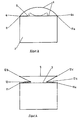
- Bei der in Figur 3 dargestellten Ausführungsform ist das flächig ausgebildete Anzeigeelement 9 mit zwei Seitenkanten 6, 6a über Befestigungsstellen 11, 11a mit dem Fangsack 2, insbesondere dessen Deckfläche 5 verbunden. Die gestreckte Länge des streifenförmigen Anzeigeelementes 9 ist größer, als der Abstand zwischen den Befestigungsstellen 11, 11a. Aus Figur 3 ist die Normalposition ersichtlich, d.h. die Stellung während des Füllens des Fangsackes 2. Ist der Fangsack 2 gefüllt, fällt das Anzeigeelement 9 nach unten und legt sich auf die Oberfläche, d.h. die Deckfläche 5 des Fangsackes 2. Diese Position ist in gestrichelter Form dargestellt.
- Bei der Ausführungsform nach Figur 4 sind ebenfalls zwei Befestigungsstellen 11, 11a für das Anzeigeelement 9 vorgesehen. Es ist ebenfalls der Deckfläche 5 zugeordnet. Zwischen den beiden Befestigungsstellen 11, 11a sind jedoch weitere Gelenkstellen 12, 12a, 12b und 12c vorgesehen. Da es sich bei dem Anzeigeelement 9 um einen Gewebestreifen oder eine Folie handelt, können die Gelenkstellen 12, 12a, 12b, 12c, und die Befestigungsstellen 11, 11a durch scharfe Knickkanten oder Filmschanierstellen gebildet werden. Hierdurch wird ein gezieltes Zusammenlegen und Aufrichten erreicht.
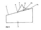
- Eine ähnliche Ausbildung ist in Figur 5 dargestellt. Es handelt sich jedoch hierbei nicht um eine Rückansicht wie bei Figur 4. Das Anzeigeelement 9 ist nicht quer auf der Deckfläche 5 angeordnet, sondern längs zum Fangsack. Die Befestigungsstellen 11, 11a des Anzeigeelementes sind also auf der Längsachse des Fangsackes 2 versetzt zueinander angeordnet. Es sind zwei weitere Gelenkstellen zu den ebenfalls als Gelenkstellen ausgebildeten Befestigungsstellen 11, 11a zusätzlich im Zwischenbereich vorgesehen und mit 12 und 12a bezeichnet. Die aufgerichtete Stellung, das ist die Stellung, bei der eine Füllung noch stattfindet, ist durchgezogen dargestellt, während die zusammengefaltete Stellung durch eine gestrichelte Linie dargestellt ist.
Claims (10)
Priority Applications (1)
| Application Number | Priority Date | Filing Date | Title |
|---|---|---|---|
| AT89104387T ATE61199T1 (de) | 1988-04-27 | 1989-03-13 | Sammel- oder fangvorrichtung mit fuellstandsanzeige fuer ein garten-, rasen- oder landschaftspflegegeraet. |
Applications Claiming Priority (2)
| Application Number | Priority Date | Filing Date | Title |
|---|---|---|---|
| DE3814119 | 1988-04-27 | ||
| DE3814119A DE3814119A1 (de) | 1988-04-27 | 1988-04-27 | Sammel- oder fangvorrichtung mit fuellstandsanzeige fuer ein garten-, rasen- oder landschaftspflegegeraet |
Publications (2)
| Publication Number | Publication Date |
|---|---|
| EP0339226A1 EP0339226A1 (de) | 1989-11-02 |
| EP0339226B1 true EP0339226B1 (de) | 1991-03-06 |
Family
ID=6352934
Family Applications (1)
| Application Number | Title | Priority Date | Filing Date |
|---|---|---|---|
| EP89104387A Expired - Lifetime EP0339226B1 (de) | 1988-04-27 | 1989-03-13 | Sammel- oder Fangvorrichtung mit Füllstandsanzeige für ein Garten-, Rasen- oder Landschaftspflegegerät |
Country Status (3)
| Country | Link |
|---|---|
| EP (1) | EP0339226B1 (de) |
| AT (1) | ATE61199T1 (de) |
| DE (2) | DE3814119A1 (de) |
Cited By (1)
| Publication number | Priority date | Publication date | Assignee | Title |
|---|---|---|---|---|
| DE4227677A1 (de) * | 1992-08-21 | 1994-04-21 | Gutbrod Werke Gmbh | Füllstandsanzeiger an einer Fangeinrichtung für motorisch betriebene Gartengeräte wie Rasenmäher oder Vertikutierer |
Families Citing this family (5)
| Publication number | Priority date | Publication date | Assignee | Title |
|---|---|---|---|---|
| JP3037794B2 (ja) * | 1991-09-25 | 2000-05-08 | 本田技研工業株式会社 | 刈取り機のグラスバッグ満杯検出装置 |
| DE4232198C2 (de) * | 1991-09-25 | 2001-12-13 | Honda Motor Co Ltd | Anzeigevorrichtung für den Füllungsgrad des Grasfangkorbes eines Rasenmähers |
| DE9312463U1 (de) * | 1993-08-19 | 1993-10-21 | Wolf - Geräte GmbH Vertriebsgesellschaft KG, 57518 Betzdorf | Vorrichtung zur Anzeige des Füllstandes im Fangkorb von Rasenmähern |
| GB2316596B (en) * | 1996-08-28 | 2000-07-12 | Atco Qualcast Ltd | Grassbox indicator devices for lawnmowers |
| GB9717093D0 (en) * | 1997-08-12 | 1997-10-15 | Bosch Gmbh Robert | Improvements in or relating to vegetation cutters |
Family Cites Families (13)
| Publication number | Priority date | Publication date | Assignee | Title |
|---|---|---|---|---|
| DE7143941U (de) * | 1972-02-17 | Hagedorn G | Grasfangvorrichtung für Sichelmäher | |
| DE7828438U1 (de) * | 1979-03-22 | Sabo-Maschinenfabrik Gmbh & Co Produktionsgesellschaft Kg, 5270 Gummersbach | Grasfangkorb für Rasenmäher Sabo-Maschinenfabrik GmbH & Co Produktionsgesellschaft KG, 5270 Gummersbach | |
| DE8406041U1 (de) * | 1984-07-19 | Norddeutsche Seekabelwerke Ag, 2890 Nordenham | Gartengerät, insbesondere Rasenmäher, Laubsammler, od. dgl. | |
| DE6902002U (de) * | 1969-01-20 | 1969-05-29 | Zuendapp Werke Gmbh | Rasenmaeher mit grasauffangvorrichtung |
| GB1242515A (en) * | 1969-02-17 | 1971-08-11 | Victa Ltd | Improvement in grasscatchers for rotary mowers |
| US3606747A (en) * | 1970-03-05 | 1971-09-21 | Joseph F Bauman | Indicating means for grass catching bag and the like |
| DE2337012A1 (de) * | 1973-07-20 | 1975-02-06 | As Motor Gmbh & Co Kg | Rasenmaeher mit heckauswurf |
| US3971198A (en) * | 1974-12-23 | 1976-07-27 | Arctic Enterprises, Inc. | Collector for a power lawnmower |
| GB2101864B (en) * | 1981-06-11 | 1984-12-12 | Daniel Bryan Payen | Lawn mower grass collection indicator |
| WO1984003413A1 (en) * | 1983-03-11 | 1984-09-13 | Sunbeam Corp | Rotary lawnmower |
| FR2571587B1 (fr) * | 1984-10-17 | 1987-10-30 | Garnot Guy | Aspirateur a gazon |
| US4761943A (en) * | 1985-02-06 | 1988-08-09 | Parker Sweeper Company | Mobile vacuum system for use with a riding tractor mower |
| DE8618664U1 (de) * | 1986-07-11 | 1986-11-13 | AL-KO Kober AG, 89359 Kötz | Motorisch angetriebener Rasenmäher |
-
1988
- 1988-04-27 DE DE3814119A patent/DE3814119A1/de active Granted
-
1989
- 1989-03-13 AT AT89104387T patent/ATE61199T1/de not_active IP Right Cessation
- 1989-03-13 EP EP89104387A patent/EP0339226B1/de not_active Expired - Lifetime
- 1989-03-13 DE DE8989104387T patent/DE58900061D1/de not_active Expired - Lifetime
Cited By (1)
| Publication number | Priority date | Publication date | Assignee | Title |
|---|---|---|---|---|
| DE4227677A1 (de) * | 1992-08-21 | 1994-04-21 | Gutbrod Werke Gmbh | Füllstandsanzeiger an einer Fangeinrichtung für motorisch betriebene Gartengeräte wie Rasenmäher oder Vertikutierer |
Also Published As
| Publication number | Publication date |
|---|---|
| EP0339226A1 (de) | 1989-11-02 |
| ATE61199T1 (de) | 1991-03-15 |
| DE58900061D1 (de) | 1991-04-11 |
| DE3814119A1 (de) | 1989-11-09 |
| DE3814119C2 (de) | 1990-06-21 |
Similar Documents
| Publication | Publication Date | Title |
|---|---|---|
| EP0638228B1 (de) | Lösbare Einrichtung zum Anschliessen eines Fangbehälters an eine Mäheinheit | |
| DE3130898C2 (de) | ||
| EP0920798A1 (de) | Vorrichtung, Auswurfgehäuse und Mähgerät | |
| DE3814119C2 (de) | ||
| DE69814409T2 (de) | Aufsitzmäher mit füllstandanzeigevorrichtung | |
| EP1266551A2 (de) | Arbeitsgerät zum Anbau an ein Fahrzeug | |
| DE3642012C2 (de) | ||
| DE60216167T2 (de) | Sammelbehälter | |
| DE69102348T2 (de) | Fangvorrichtung für einen Rasenmäher, mit einem abnehmbaren Boden, die erlaubt, das Schnittgut direkt fallen zu lassen. | |
| DE1680136C3 (de) | ||
| DE3328081C1 (de) | Fangvorrichtung fuer das Schnittgut eines Rasenmaehers | |
| DE8805535U1 (de) | Sammel- oder Fangvorrichtung mit Füllstandanzeige für ein Garten-, Rasen- oder Landschaftspflegegerät | |
| DE102010002820B4 (de) | Pollenmessvorrichtung | |
| EP0639321B1 (de) | Vorrichtung zur Anzeige des Füllstandes im Fangkorb von Rasenmähern | |
| DE4100593C2 (de) | ||
| EP0632954B1 (de) | Bodenbearbeitungsgerät mit einem Sammelbehälter | |
| DE3505637C2 (de) | ||
| DE9310940U1 (de) | Fangvorrichtung fuer einen rasenmaeher | |
| DE4232198C2 (de) | Anzeigevorrichtung für den Füllungsgrad des Grasfangkorbes eines Rasenmähers | |
| DE3643854C2 (de) | ||
| DE4228574A1 (de) | Sammelbehälter für Abfallgut von Strassen- und Rasenpflegegeräten | |
| DE69809151T2 (de) | Mehrzweckmäher | |
| DE19505321C2 (de) | Fahrbare Anhängevorrichtung mit einem Sammelbehälter für Mähgut, Kehrgut o. dgl. | |
| DE6902002U (de) | Rasenmaeher mit grasauffangvorrichtung | |
| DE19737504C2 (de) | Tierschutzgerechte Lebendfang-Röhrenfalle |
Legal Events
| Date | Code | Title | Description |
|---|---|---|---|
| PUAI | Public reference made under article 153(3) epc to a published international application that has entered the european phase |
Free format text: ORIGINAL CODE: 0009012 |
|
| AK | Designated contracting states |
Kind code of ref document: A1 Designated state(s): AT BE CH DE ES FR GB IT LI LU NL |
|
| 17P | Request for examination filed |
Effective date: 19891115 |
|
| 17Q | First examination report despatched |
Effective date: 19900122 |
|
| GRAA | (expected) grant |
Free format text: ORIGINAL CODE: 0009210 |
|
| ITF | It: translation for a ep patent filed | ||
| AK | Designated contracting states |
Kind code of ref document: B1 Designated state(s): AT DE FR GB IT |
|
| REF | Corresponds to: |
Ref document number: 61199 Country of ref document: AT Date of ref document: 19910315 Kind code of ref document: T |
|
| REF | Corresponds to: |
Ref document number: 58900061 Country of ref document: DE Date of ref document: 19910411 |
|
| GBT | Gb: translation of ep patent filed (gb section 77(6)(a)/1977) | ||
| ET | Fr: translation filed | ||
| PLBI | Opposition filed |
Free format text: ORIGINAL CODE: 0009260 |
|
| 26 | Opposition filed |
Opponent name: GUTBROD WERKE GMBH Effective date: 19911121 |
|
| PLAB | Opposition data, opponent's data or that of the opponent's representative modified |
Free format text: ORIGINAL CODE: 0009299OPPO |
|
| R26 | Opposition filed (corrected) |
Opponent name: GUTBROD WERKE GMBH Effective date: 19911121 |
|
| PLBN | Opposition rejected |
Free format text: ORIGINAL CODE: 0009273 |
|
| STAA | Information on the status of an ep patent application or granted ep patent |
Free format text: STATUS: OPPOSITION REJECTED |
|
| 27O | Opposition rejected |
Effective date: 19930426 |
|
| ITPR | It: changes in ownership of a european patent |
Owner name: CESSIONE;SABO - MASCHINENFABRIK GMBH |
|
| REG | Reference to a national code |
Ref country code: FR Ref legal event code: TP |
|
| REG | Reference to a national code |
Ref country code: GB Ref legal event code: 732E |
|
| REG | Reference to a national code |
Ref country code: FR Ref legal event code: CD |
|
| PGFP | Annual fee paid to national office [announced via postgrant information from national office to epo] |
Ref country code: AT Payment date: 19970320 Year of fee payment: 9 |
|
| PG25 | Lapsed in a contracting state [announced via postgrant information from national office to epo] |
Ref country code: AT Free format text: LAPSE BECAUSE OF NON-PAYMENT OF DUE FEES Effective date: 19980313 |
|
| REG | Reference to a national code |
Ref country code: GB Ref legal event code: IF02 |
|
| PG25 | Lapsed in a contracting state [announced via postgrant information from national office to epo] |
Ref country code: IT Free format text: LAPSE BECAUSE OF NON-PAYMENT OF DUE FEES;WARNING: LAPSES OF ITALIAN PATENTS WITH EFFECTIVE DATE BEFORE 2007 MAY HAVE OCCURRED AT ANY TIME BEFORE 2007. THE CORRECT EFFECTIVE DATE MAY BE DIFFERENT FROM THE ONE RECORDED. Effective date: 20050313 |
|
| PGFP | Annual fee paid to national office [announced via postgrant information from national office to epo] |
Ref country code: GB Payment date: 20080327 Year of fee payment: 20 |
|
| PGFP | Annual fee paid to national office [announced via postgrant information from national office to epo] |
Ref country code: DE Payment date: 20080219 Year of fee payment: 20 Ref country code: FR Payment date: 20080317 Year of fee payment: 20 |
|
| REG | Reference to a national code |
Ref country code: GB Ref legal event code: PE20 Expiry date: 20090312 |
|
| PG25 | Lapsed in a contracting state [announced via postgrant information from national office to epo] |
Ref country code: GB Free format text: LAPSE BECAUSE OF EXPIRATION OF PROTECTION Effective date: 20090312 |