EP0338864A2 - Magneto-optische Wiedergabeköpfe - Google Patents
Magneto-optische Wiedergabeköpfe Download PDFInfo
- Publication number
- EP0338864A2 EP0338864A2 EP89304020A EP89304020A EP0338864A2 EP 0338864 A2 EP0338864 A2 EP 0338864A2 EP 89304020 A EP89304020 A EP 89304020A EP 89304020 A EP89304020 A EP 89304020A EP 0338864 A2 EP0338864 A2 EP 0338864A2
- Authority
- EP
- European Patent Office
- Prior art keywords
- optical
- magneto
- playback head
- waveguide
- optical waveguide
- Prior art date
- Legal status (The legal status is an assumption and is not a legal conclusion. Google has not performed a legal analysis and makes no representation as to the accuracy of the status listed.)
- Granted
Links
Images


Classifications
-
- G—PHYSICS
- G11—INFORMATION STORAGE
- G11B—INFORMATION STORAGE BASED ON RELATIVE MOVEMENT BETWEEN RECORD CARRIER AND TRANSDUCER
- G11B11/00—Recording on or reproducing from the same record carrier wherein for these two operations the methods are covered by different main groups of groups G11B3/00 - G11B7/00 or by different subgroups of group G11B9/00; Record carriers therefor
- G11B11/10—Recording on or reproducing from the same record carrier wherein for these two operations the methods are covered by different main groups of groups G11B3/00 - G11B7/00 or by different subgroups of group G11B9/00; Record carriers therefor using recording by magnetic means or other means for magnetisation or demagnetisation of a record carrier, e.g. light induced spin magnetisation; Demagnetisation by thermal or stress means in the presence or not of an orienting magnetic field
- G11B11/105—Recording on or reproducing from the same record carrier wherein for these two operations the methods are covered by different main groups of groups G11B3/00 - G11B7/00 or by different subgroups of group G11B9/00; Record carriers therefor using recording by magnetic means or other means for magnetisation or demagnetisation of a record carrier, e.g. light induced spin magnetisation; Demagnetisation by thermal or stress means in the presence or not of an orienting magnetic field using a beam of light or a magnetic field for recording by change of magnetisation and a beam of light for reproducing, i.e. magneto-optical, e.g. light-induced thermomagnetic recording, spin magnetisation recording, Kerr or Faraday effect reproducing
- G11B11/10532—Heads
- G11B11/10541—Heads for reproducing
- G11B11/10543—Heads for reproducing using optical beam of radiation
- G11B11/10545—Heads for reproducing using optical beam of radiation interacting directly with the magnetisation on the record carrier
-
- G—PHYSICS
- G11—INFORMATION STORAGE
- G11B—INFORMATION STORAGE BASED ON RELATIVE MOVEMENT BETWEEN RECORD CARRIER AND TRANSDUCER
- G11B11/00—Recording on or reproducing from the same record carrier wherein for these two operations the methods are covered by different main groups of groups G11B3/00 - G11B7/00 or by different subgroups of group G11B9/00; Record carriers therefor
- G11B11/10—Recording on or reproducing from the same record carrier wherein for these two operations the methods are covered by different main groups of groups G11B3/00 - G11B7/00 or by different subgroups of group G11B9/00; Record carriers therefor using recording by magnetic means or other means for magnetisation or demagnetisation of a record carrier, e.g. light induced spin magnetisation; Demagnetisation by thermal or stress means in the presence or not of an orienting magnetic field
- G11B11/105—Recording on or reproducing from the same record carrier wherein for these two operations the methods are covered by different main groups of groups G11B3/00 - G11B7/00 or by different subgroups of group G11B9/00; Record carriers therefor using recording by magnetic means or other means for magnetisation or demagnetisation of a record carrier, e.g. light induced spin magnetisation; Demagnetisation by thermal or stress means in the presence or not of an orienting magnetic field using a beam of light or a magnetic field for recording by change of magnetisation and a beam of light for reproducing, i.e. magneto-optical, e.g. light-induced thermomagnetic recording, spin magnetisation recording, Kerr or Faraday effect reproducing
- G11B11/10532—Heads
-
- G—PHYSICS
- G11—INFORMATION STORAGE
- G11B—INFORMATION STORAGE BASED ON RELATIVE MOVEMENT BETWEEN RECORD CARRIER AND TRANSDUCER
- G11B11/00—Recording on or reproducing from the same record carrier wherein for these two operations the methods are covered by different main groups of groups G11B3/00 - G11B7/00 or by different subgroups of group G11B9/00; Record carriers therefor
- G11B11/10—Recording on or reproducing from the same record carrier wherein for these two operations the methods are covered by different main groups of groups G11B3/00 - G11B7/00 or by different subgroups of group G11B9/00; Record carriers therefor using recording by magnetic means or other means for magnetisation or demagnetisation of a record carrier, e.g. light induced spin magnetisation; Demagnetisation by thermal or stress means in the presence or not of an orienting magnetic field
- G11B11/105—Recording on or reproducing from the same record carrier wherein for these two operations the methods are covered by different main groups of groups G11B3/00 - G11B7/00 or by different subgroups of group G11B9/00; Record carriers therefor using recording by magnetic means or other means for magnetisation or demagnetisation of a record carrier, e.g. light induced spin magnetisation; Demagnetisation by thermal or stress means in the presence or not of an orienting magnetic field using a beam of light or a magnetic field for recording by change of magnetisation and a beam of light for reproducing, i.e. magneto-optical, e.g. light-induced thermomagnetic recording, spin magnetisation recording, Kerr or Faraday effect reproducing
- G11B11/1055—Disposition or mounting of transducers relative to record carriers
- G11B11/10552—Arrangements of transducers relative to each other, e.g. coupled heads, optical and magnetic head on the same base
- G11B11/10554—Arrangements of transducers relative to each other, e.g. coupled heads, optical and magnetic head on the same base the transducers being disposed on the same side of the carrier
-
- G—PHYSICS
- G11—INFORMATION STORAGE
- G11B—INFORMATION STORAGE BASED ON RELATIVE MOVEMENT BETWEEN RECORD CARRIER AND TRANSDUCER
- G11B11/00—Recording on or reproducing from the same record carrier wherein for these two operations the methods are covered by different main groups of groups G11B3/00 - G11B7/00 or by different subgroups of group G11B9/00; Record carriers therefor
- G11B11/10—Recording on or reproducing from the same record carrier wherein for these two operations the methods are covered by different main groups of groups G11B3/00 - G11B7/00 or by different subgroups of group G11B9/00; Record carriers therefor using recording by magnetic means or other means for magnetisation or demagnetisation of a record carrier, e.g. light induced spin magnetisation; Demagnetisation by thermal or stress means in the presence or not of an orienting magnetic field
- G11B11/105—Recording on or reproducing from the same record carrier wherein for these two operations the methods are covered by different main groups of groups G11B3/00 - G11B7/00 or by different subgroups of group G11B9/00; Record carriers therefor using recording by magnetic means or other means for magnetisation or demagnetisation of a record carrier, e.g. light induced spin magnetisation; Demagnetisation by thermal or stress means in the presence or not of an orienting magnetic field using a beam of light or a magnetic field for recording by change of magnetisation and a beam of light for reproducing, i.e. magneto-optical, e.g. light-induced thermomagnetic recording, spin magnetisation recording, Kerr or Faraday effect reproducing
- G11B11/1055—Disposition or mounting of transducers relative to record carriers
- G11B11/1058—Flying heads
-
- G—PHYSICS
- G11—INFORMATION STORAGE
- G11B—INFORMATION STORAGE BASED ON RELATIVE MOVEMENT BETWEEN RECORD CARRIER AND TRANSDUCER
- G11B5/00—Recording by magnetisation or demagnetisation of a record carrier; Reproducing by magnetic means; Record carriers therefor
- G11B5/127—Structure or manufacture of heads, e.g. inductive
- G11B5/31—Structure or manufacture of heads, e.g. inductive using thin films
- G11B5/3109—Details
- G11B5/313—Disposition of layers
-
- G—PHYSICS
- G11—INFORMATION STORAGE
- G11B—INFORMATION STORAGE BASED ON RELATIVE MOVEMENT BETWEEN RECORD CARRIER AND TRANSDUCER
- G11B5/00—Recording by magnetisation or demagnetisation of a record carrier; Reproducing by magnetic means; Record carriers therefor
- G11B5/127—Structure or manufacture of heads, e.g. inductive
- G11B5/31—Structure or manufacture of heads, e.g. inductive using thin films
- G11B5/3163—Fabrication methods or processes specially adapted for a particular head structure, e.g. using base layers for electroplating, using functional layers for masking, using energy or particle beams for shaping the structure or modifying the properties of the basic layers
-
- G—PHYSICS
- G11—INFORMATION STORAGE
- G11B—INFORMATION STORAGE BASED ON RELATIVE MOVEMENT BETWEEN RECORD CARRIER AND TRANSDUCER
- G11B5/00—Recording by magnetisation or demagnetisation of a record carrier; Reproducing by magnetic means; Record carriers therefor
- G11B5/48—Disposition or mounting of heads or head supports relative to record carriers ; arrangements of heads, e.g. for scanning the record carrier to increase the relative speed
- G11B5/58—Disposition or mounting of heads or head supports relative to record carriers ; arrangements of heads, e.g. for scanning the record carrier to increase the relative speed with provision for moving the head for the purpose of maintaining alignment of the head relative to the record carrier during transducing operation, e.g. to compensate for surface irregularities of the latter or for track following
- G11B5/60—Fluid-dynamic spacing of heads from record-carriers
- G11B5/6005—Specially adapted for spacing from a rotating disc using a fluid cushion
-
- G—PHYSICS
- G11—INFORMATION STORAGE
- G11B—INFORMATION STORAGE BASED ON RELATIVE MOVEMENT BETWEEN RECORD CARRIER AND TRANSDUCER
- G11B7/00—Recording or reproducing by optical means, e.g. recording using a thermal beam of optical radiation by modifying optical properties or the physical structure, reproducing using an optical beam at lower power by sensing optical properties; Record carriers therefor
- G11B7/12—Heads, e.g. forming of the optical beam spot or modulation of the optical beam
- G11B7/122—Flying-type heads, e.g. analogous to Winchester type in magnetic recording
-
- G—PHYSICS
- G11—INFORMATION STORAGE
- G11B—INFORMATION STORAGE BASED ON RELATIVE MOVEMENT BETWEEN RECORD CARRIER AND TRANSDUCER
- G11B7/00—Recording or reproducing by optical means, e.g. recording using a thermal beam of optical radiation by modifying optical properties or the physical structure, reproducing using an optical beam at lower power by sensing optical properties; Record carriers therefor
- G11B7/12—Heads, e.g. forming of the optical beam spot or modulation of the optical beam
- G11B7/123—Integrated head arrangements, e.g. with source and detectors mounted on the same substrate
- G11B7/124—Integrated head arrangements, e.g. with source and detectors mounted on the same substrate the integrated head arrangements including waveguides
Definitions
- This invention relates to magneto-optical playback heads.
- Figure 1 shows an example of a known optical head for a magneto-optical disc 1 forming a recording medium.
- a beam of light from a laser beam source 2 is passed through a grating 3, a lens system 4, a polarizer 5, a beam splitter 6, and an objective lens 7 to be converged on the magneto-optical recording disc 1.
- the return light beam reflected from the disc 1 is reflected by the beam splitter 6 into a direction at an angle of 90° with its original path, passed through a half-wave plate 8, and subjected to differential detection by means of a polarization beam splitter 9 and photodiodes 10 and 11, so that a playback signal is obtained.
- the reference numerals 12 and 13 denote cylindrical lenses.
- a magneto-optical recording system for recording a signal by a magnetic-field modulation method, and capable of real-time over-writing using a single laser beam. That is, as shown in Figure 2, while a recording laser beam 18 is applied to one side of a magneto-optical disc 1 made up of a transparent substrate 15, a magneto-optical recording layer 16, and a protective layer 17, a magnetic head 21 mounted on a slider similar to a head for a magnetic disc is disposed to face the side of the disc 1 opposite to the side irradiated by the beam, and a signal to be recorded is supplied to the magnetic head 21. Playback is performed with a laser beam in the manner described with reference to Figure 1.
- a branch type optical waveguide in which the end of one branch waveguide is provided with a semiconductor laser as a light source, the end of the other branch waveguide is provided with a photodetector, and the end of the common waveguide is arranged to confront a recording medium, so that an emitted light beam from the semiconductor laser is lead through one branch waveguide and the common waveguide to impinge on the recording medium, and the reflected beam from the recording medium is guided from the end of the common waveguide to the other branch waveguide and allowed to enter the photodetector, and thereby, a playback signal is obtained (see Japanese laid-open patent specifications 60/59547, 60/59548 and 61/66238).
- An optical head has also been proposed which has a semiconductor laser and photodetectors, disposed at both sides thereof, integrally formed on a substrate, in which a light beam emitted from the semiconductor laser is applied to a recording medium and the reflected light therefrom is received by the photodetectors at both sides (see Japanese laid-open patent specification 62/192032).
- a magneto-optical playback head comprising:
- a magneto-optical playback head comprising:
- the present invention relates to a magneto-optical playback head for reading a signal from a magneto-optical recording medium making use of the magneto-optical effect.
- the reading of a signal by magneto-optical effect makes use of rotation of the plane of polarization due to interaction between magnetization recorded in a magnetic medium and linearly polarized light.
- Media with a signal recorded therein in such a manner include magneto-optical discs in which recording is made, not using a bias magnetic field, but utilizing stray magnetic field in a medium heated by a laser beam, and those in which recording is made using a bias magnetic field, for example, an auxiliary magnetic field (dc magnetic field), and magnetic-field modulation.
- dc magnetic field auxiliary magnetic field
- the recording can also be performed by electromagnetic induction using a ring head or a single pole type head as described in detail below with reference to an embodiment of the invention.
- An embodiment of optical playback head comprises a first optical waveguide, of which one end is provided with a light source and the other end is arranged to confront a recording medium, and a second optical waveguide, of which one end is provided with a photodetector, and further comprises metal-clad mode filters, which are formed by laminating conductive layers to the first and second optical waveguides with insulating layers interposed therebetween, the conductive layers being arranged at a predetermined angle to each other.
- the angle of inclination of the conductive layer of the metal-clad filter (corresponding to a polarizer) formed on the first optical waveguide with respect to a reference plan is a
- the angle of inclination of the conductive layer of the metal-clad mode filter (corresponding to an analyzer) formed on the second optical waveguide with respect to the reference plane is ⁇
- the metal-clad mode filters for the first optical waveguide and the second optical waveguide in such a way that they form a predetermined angle, that is, an angle of 45° or an angle close to 45° with each other, the playback signal can be maximized.
- playback head uses optical waveguides instead of a large lens system, and since the polarizer and the analyzer are formed by metal-clad mode filters, it is possible to mount the head on a light-weight slider.
- the return light from the recording medium is split into two parts and the respective signals are read differentially, a signal twice as large as each is obtained, while dc components in the signals are suppressed or cancelled by each other, so that the signal-to-noise ratio (S/N) of the playback signal can be substantially improved.
- S/N signal-to-noise ratio
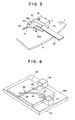
- Figures 3 to 5 as well as Figures 6A to 6D show an embodiment of optical playback head according to the present invention.
- a recording medium such as a magneto-optical disc 31, a recording track 32 thereon, and a light-weight slider 33, having on its end face 33A or 33B an optical playback head 34 according to this invention.
- the slider 33 has, for example, a width W of 3 mm and a height H of 1 mm, and is placed against the disc 31 by means of a gimbal mechanism exerting a required amount of pressure on the disc 31, that is, the slider 33 is attached to the free end of a resilient member 25.
- the slider 33 is, for example, fitted to a metallic olate 62 having a protrusion 61 on its top surface, so that the free end of the resilient member 25 comes into abutment with the protrusion 61, allowing the slider 33 to swing about the resilient member 25.
- the wiring from the head 34 is led out through a flexible wiring lead 79.
- the slider 33 can float over the medium 31 by means of an air flow produced by rotation of the disc 31, indicated by the arrow a.
- the optical playback head 34 is composed, as shown in Figures 4 and 5, of a semiconductor laser diode 36 (for example, a GaAs from junction laser diode) forming a light source, a photodetector 37 formed, for example, of a PIN photodiode or an avalanche photodiode, a first optical waveguide 38, of which one end is in contact or confrontation with the laser diode 36 and the other end is in confrontation with the disc 31, so that a beam of light emitted from the laser diode 36 is thrown directly on the surface of the disc 31, and a second optical waveguide 40, which is combined with the first optical waveguide 38 to form a cross type optical directional coupler 39, so that the beam of light reflected from the disc 31 is led from the first optical waveguide 38 to the photodetector 37 through the directional coupler 39, all these elements being disposed on a substrate 35.
- a semiconductor laser diode 36 for example, a GaAs from junction laser diode
- the light emitted from the laser diode 36 is linearly polarized light having a plane of polarization in the direction parallel to its active layer, and its ratio of polarization indicating the degree of linear polarization is 80 to 100.
- Such a laser beam is introduced into the optical waveguide without experiencing mode conversion.
- the first and second optical waveguides 38 and 40 are each formed, for example, of an ion-exchanged waveguide made of soda glass dipped in a solution of KNO s whereby K + ions are exchanged. More particularly, the first and second optical waveguides 38 and 40 are formed by being piled up and crossed with each other, that is, as shown in Figure 6D (a sectional view taken along line D - D in Figure 5), the first optical waveguide 38 is formed by an ion exchange technique on a sputtered glass film 43 on a soda glass substrate 42, another sputtered glass film 44 is formed thereon, and a second optical waveguide 40 is formed by the ion exchange technique on the sputtered glass film 44.
- each optical waveguide 38 and 40 are adjusted so that a single mode may be obtained, namely, the electric field may be distributed as a Gaussian distribution within the optical waveguides 38 and 40.
- the wavelength of the light X 0.78 ⁇ m
- the first optical waveguide 38 is formed in a tapered optical waveguide, that is, it becomes thinner (its width W becomes smaller) towards its end where it confronts the magneto-optical disc 31. It can also be formed in an untapered, or straight, waveguide with a uniform width.
- the second optical waveguide 40 while it is arranged in confrontation or contact with the photodetector 37 at its one end, is closed on the way to the other end.
- the laser diode 36 provides a linearly polarized beam having a sufficiently high ratio of polarization
- the metal-clad mode filters 46 and 47 serving respectively as a polarizer and an analyzer, for the first optical waveguide 38 midway between the laser diode 36 and the directional coupler 39, and for the second optical waveguide 40 midway between the photodetector 37 and the directional coupler 39.
- the metal-clad mode filters 46 and 47 are formed respectively by depositing conductive layers 50 and 51 made, for example, of AI over the first optical waveguide 38 and second optical waveguide 40 with buffer layers 48 and 49 of insulating layers made, for example, of Si0 2 interposed therebetween.
- the metal-clad mode filters 46 and 47 transmit the TE mode therethrough and absorb the TM mode.
- the Si0 2 layer for the buffer layer 48 is formed with a thickness, for example, of 0.2 ⁇ m, so that the TE mode does not suffer a loss, and because the loss of the TM mode decreases as the film is made thicker.
- the directional coupler 39 is coupled through the evanescent field.
- an angle of crossing y of the optical waveguides 38 and 40 is preferred to be set to less than 1°.
- y 1°
- w 5 ⁇ m
- the space I at the crossing portion becomes approximately 600 ⁇ m.
- the active layer 56 sandwiched between the p type clad layer 54 and then type clad layer 55 is arranged to be at an angle of inclination a the same as the angle of inclination a of the metal-clad mode filter 46 serving as a polarizer.
- the laser diode 36 although not shown in Figure 4, one that is cut out such that its active layer is at an angle of a with the surface of the substrate 35 is used.
- the first optical waveguide 38 is formed such that its surface 38a is also inclined at an angle of a along its entire length as shown in Figure 6D, and in addition thereto, the surface 40a of the second optical waveguide 40 at the directional coupler 39 is also formed to be inclined at an angle of a in parallel with the first optical waveguide 38.
- the second optical waveguide 40 is formed such that its surface 40a is inclined at an angle ⁇ at the metal-clad filter 47.
- the laser diode 36 is not inclined, but the active layer 56 is held horizontal and to form the first and second optical waveguides 38 and 40 such that their surfaces 38a and 40a are held horizontal, whereas they are inclined at an angle a and angle ⁇ , respectively, at the metal-clad mode filters 46 and 47.
- the intensity of the light is lowered as compared with the example shown in the drawing.
- a beam of light emitted from the laser diode 36 is introduced into the first optical waveguide 38, propagated through the metal-clad mode filter 46, and thrown on the surface of the disc 31.
- the plane of polarization of the reflected light from the disc 31 exhibits Kerr rotation, according to the directions of the recorded magnetization (for example, upward magnetization or downward magnetization) in the disc 31, of an angle of + 8 or - ⁇ with respect to the plane of polarization of the incident light. Since the spacing t between the end of the head and the disc 31 is less than 1 ⁇ m, the reflected light is introduced into the first optical waveguide 38 from its end, propagated to the second optical waveguide 40 through the directional coupler 39, and passed through a bent midway portion of the waveguide portion to be allowed to enter the metal-clad mode filter 47 forming an analyzer.
- the reflected light passed through the metal-clad mode filter 47 forming an analyzer is received by the photodetector 37 and subjected, for example, to differential detection, so that a playback signal is derived.
- the optical playback head since the optical waveguides 38 and 40 are coupled through the directional coupler 39, so that the reflected light from the disc 31 is propagated to the second optical waveguide 40 by means of the directional coupler 39, mode conversion in which the direction of the plane of polarization is changed hardly occurs. Further, by the use of the directional coupler 39, the return light of the reflected light through the first optical waveguide 38 to the side of the laser diode 36 is limited, and thereby, oscillation of the laser diode 36 is prevented from being unstable.
- the metal-clad mode filters 46 and 47 are used for the polarizer and analyzer, and their buffer layers 48 and 49, and conductive layers 50 and 51 are arranged so that the angle formed therebetween may become 45° or close to 45°, the playback signal can be maximized.
- the optical system can be made smaller than prior ones by the use of the optical waveguides 38 and 40, the directional coupler 39, and the metal-clad mode filters 46 and 47 as described above, it can be formed on an end face 33A of a light-weight slider 33. Hence, high speed access and formation of narrower tracks can be attained.
- Figure 7 shows an example of a magneto-optical recording and playback head utilizing the embodiment of optical playback head according to the present invention.
- This recording and playback head is for magnetic recording, by electromagnetic induction, and for optical playback, and is arranged to be capable of high-speed overwrite and high-speed access.
- a magneto-optical disc 71 is formed by laminating a reflecting film 73, a magneto-optical recording film 74, and a protective film 75 over a substrate 72, while an embodiment of magneto-optical recording and playback head 76 of the present invention is formed of a thin-film magnetic recording head 77 and an optical playback head 78 according to the present invention as described above placed side by side.
- the recording and playback head 76 is formed on and end face 33A of a light-weight slider 33 as shown in Figure 3.
- the light-weight sliders 33 with recording and playback heads 76 of the same structure mounted thereon may be disposed to confront both sides of the disc 71.
- the thin-film magnetic head is made of a magnetic thin-film of high magnetic permeability and high saturation magnetic flux density, and is structured as a magnetic circuit portion 80 in which a magnetic gap g is formed and a thin-film coiled conductor 81 is arranged to cross the magnetic circuit portion 80.
- the optical playback head 78 is made up of an optical waveguide 38, the second optical waveguide 40, and the cross type optical directional coupler 39 formed by both the optical waveguides 38 and 40, and has the first and second optical waveguides 38 and 40 provided with the metal-clad mode filters 46 and 47 forming a polarizer and an analyzer, the laser diode 36 as a light source, and the photodetector 37 formed of a photodiode.
- One end of the first optical waveguide 38 is arranged to confront the laser diode 36 and the other end is arranged to confront the disc 71.
- One end of the second optical waveguide 40 is arranged to confront the photodetector 37.
- Reference numeral 83 denotes wiring.
- the substrate 84 for forming the recording and playback head 76 thereon an Si substrate may be used, and the photodiode service as the photodetector 37 may be formed in the Si substrate.
- recording with the thin-film magnetic head 77 effects overwrite recording into a narrow track of several ⁇ m at a high-speed of several tens to several hundreds of MHz possible.
- the arrangement of the optical playback head 78 formed of the optical waveguide element 82, the laser diode 36, and the photodetector 37 or photodiode permits the provision of miniaturized pick-up of a high S/N ratio.
- the arrangement of the thin-film magnetic recording head 76 and the optical playback head 78 on a light-weight slider 79 eliminates the need for a lens system and focusing control, and provides a small- sized, light-weight magnetic recording/optical playback head.
- the use of the recording and playback head 76 for a disc 71 makes high-speed access, high-speed transfer, and a large-capacity disc drive attainable. It further supports a double-side medium magneto-optical disc, and therefore, double-side use of the disc as well as operation of a plurality of double-side recorded media on a common spindle in a stacked manner can be implemented.
- the arrangement of the input and output optical waveguides also makes other arrangements possible such as use a branch type waveguide, or use a waveguide whose one end is provided with a laser diode, and another waveguide whose one end is provided with a photodetector, while the other ends thereof are juxtaposed close to each other facing a recording medium.
- Figures 8 and 9 show another embodiment of an optical playback head.
- This optical playback head includes a first optical waveguide 38 whose one end confronts a laser 36 and the other end confronts a magneto-optical recording medium 31 and a second optical waveguide 40 whose one end confronts a photodetector 37 of a photodiode or the like and the other end confronts the magneto-optical recording medium.
- the end faces 38a and 40a of the first and second optical waveguides 38 and 40 confronting the magneto-optical recording medium are juxtaposed close to each other.
- the first optical waveguide 38 is formed in a tapered optical waveguide, that is, it becomes thinner (its width W becomes smaller) towards its end 38a where it confronts the magneto-optical disc 31, so that it has a small sectional-area at the end 38a confronting the disc 31.
- the second optical waveguide 40 is formed so that it has a sectional area S 2 at its end 40a confronting the disc 31 larger than the sectional area S 1 at the end 38a of the first optical waveguide 38.
- the second optical waveguide 40 is formed to have a width W 2 larger than the width Wi at the end 38a of the first optical waveguide 38.
- These optical waveguides may be formed of glass in which ions are exchanged as described above, or by selectively diffusing metallic ions of Ti or the like into a monocrystalline LiTaOs substrate.
- metal-clad mode filters 46 and 47 serving as a polarizer and analyzer, respectively.
- the metal-clad mode filters 46 and 47 are formed respectively by depositing conductive layers 50 and 51 of, for example, AI over the first optical waveguide 38 and second optical waveguide 40 with buffer layers 48 and 49 of insulating layers made, for example, of Si0 2 interposed therebetween.
- the metal-clad mode filter 46 forming a polarizer and the metal-clad mode filter 47 forming an analyzer are arranged to form an angle of 45° or a predetermined angle close to 45° with each other.
- a beam of light emitted from the laser diode 36 is introduced into the first optical waveguide 38, propagated through the metal-clad mode filter 46 forming a polarizer, and thrown on the surface of the disc 31.
- the plane of polarization of the reflected light from the disc 31 exhibits Kerr rotation of an angle of + 8 or - 6 with respect to the plane of polarization of the incident light according to the directions of the recorded magnetization (for example, upward magnetization or downward magnetization) in the disc 31.
- the reflected light from the disc 31 is guided by the second optical waveguide 40 and passed through the metal-clad mode filter 47 forming an analyzer to be received by the photodetector 37 and subjected, for example, to differential detection so that a playback signal is derived.
- the optical playback output can be maximized the same as in the case described above with reference to Figures 4 and Figure 5.
- the sectional area S 2 of the end 40a of the second optical waveguide 40 is formed to be larger than the sectional area S 1 of the end 38a of the first optical waveguide 38, it is possible effectively to collect the reflected light from the disc 31 and thereby achieve an improvement in the playback output.
- the sectional area Si of the end of the first optical waveguide 38 is made small, the return light quantity of the reflected light from the disc 31 to the first optical waveguide 38 is kept small, and hence, the laser diode 36 is prevented from making unstable oscillation affected by the return light. Further, since the first optical waveguide 38 is tapered and the sectional area S 1 of its end is formed to be smaller than that of the second optical waveguide 40, formation of a narrower recording track can be achieved.
- mode conversion causing the plane of polarization in each of the first and second optical waveguides 38 and 40 to change into a different direction is kept small.
- the optical system can be constructed in a smaller size than prior ones by virtue of the above described arrangement using the optical waveguides 38 and 40 and the metal-clad mode filters 46 and 47, it can be formed on the end face 33A of a light-weight slider 33. Hence, high-speed access can be attained.
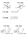
- optical output characteristics dependent on combinations of mode filters serving as the polarizer and analyzer will first be described with reference to Figures 10A, 10B, 11A, 12A, 12B and 13.
- FIG 10A is a drawing a schematically showing an AI-clad mode filter, which is formed by putting an AI layer 108 on a optical waveguide 101 formed on a substrate 100, with a buffer layer 107 of Si0 2 or the like interposed therebetween.
- the AI-clad mode filter is the one which transmits the electric field component parallel to the AI layer 108, that is, a TE mode passing mode filter.
- Figure 10B is a drawing schematically showing an amorphous Si-clad mode filter, which is formed by putting an amorphous silicon layer 110 on a optical waveguide 101 formed on a substrate 100, with a buffer layer 109 of Si0 2 or the like interposed therebetween.
- the amorphous Si layer 110 that is, a TM mode passing mode filter.
- the AI-clad mode filter for the polarizer 46 has been arranged such that its AI layer is held parallel to the active layer of the laser diode, and, referenced from this direction, the angle a of the mode filter on the side of the analyzer 47 has been changed as shown in Figure 11 B.
- the optical output at the photodetector 37 varies in accordance with sin 2 a as shown by a curve C 2 in Figure 13.
- the angle a is preferred to be smaller than the maximum angle of 45°.
- each of a combination of an AI-clad mode filter (TE mode) and an amorphous Si-clad mode filter (TM mode), a combination of an AI-clad mode filter (TE mode) and an AI-clad mode filter (TE mode), and a combination of an amorphous Si-clad mode filter (TM mode) and an amorphous Si-clad mode filter (TM mode) can be used for the two analyzers.
- these angles are selected to be in such a relation that when the optical output from one photodetector increases (or decreases) against change in the Kerr rotation angle (+ 8) on the magnetico-optical disc, the optical output from the other photodetector decreases (or increases).
- the optical playback pick-up A is made up of a semi-conductor laser diode (for example a GaAs P-N junction laser diode) 118 as a light source, first and second photodetectors 119 and 120 formed, for example, of a PIN photodiode or avalanche photodiode, and branch type optical waveguide 121 of a tree-like arrangement, all these elements being disposed on a substrate 114.
- a semi-conductor laser diode for example a GaAs P-N junction laser diode
- first and second photodetectors 119 and 120 formed, for example, of a PIN photodiode or avalanche photodiode
- branch type optical waveguide 121 of a tree-like arrangement
- the optical waveguide 121 has a first optical waveguide 121A, of which one end of 121a1 is in contact or confrontation with the laser diode 118 and the other end 121a 2 is in confrontation with the magneto-optical disc 31, for throwing an emitted beam of light from the laser diode 118 directly on the surface of the disc 31, and a second optical waveguide 121B, which is branched from the first optical waveguide 121A at a position close to the other end 121a 2 thereof, for guiding the reflected light from the surface of the disc 31 to the side of the first and second photodetectors 119 and 120.
- the second optical waveguide 121 B is further branched so that optical waveguides 121B 1 and 121B 2 are extended to their respective ends 121b 1 and 121b 2 , where the first and second photodetectors 119 and 120 are disposed confronting these ends.
- the laser diode 118 provides a linearly polarized beam having a sufficiently high ratio of polarization
- a mode filter 123 forming a polarizer for the first optical waveguide 121A and first and second mode filters 124 and 125 forming first and second analyzers respectively for the second optical waveguide 121B 1 and 121B 2 , disposed in their middle positions.
- these mode filters 123, 124 and 125 are formed respectively by depositing conductive layers 129, 130 and 131, for example, AI over the first optical waveguide 121A, one optical waveguide 121B 1 and the other optical waveguide 121B 2 of the second optical waveguide, with buffer layers 126, 127 and 128 made of an insulating layer of, for example, Si0 2 interposed therebetween.
- first mode filter 124 forming the first analyzer and the second mode filter 125 forming the second analyzer are formed to be at predetermined angles ai and a 2 , respectively, with the mode filter 123 forming a polarizer is formed to be parallel to a reference plane 1 corresponding to the active layer of the laser diode 118.
- Reference numerals 132, 133 and 134 denote sputtered coatings of soda glass in the case where waveguides are formed by thermal ion exchange.
- a beam of light emitted from the laser diode 118 is introduced into the first optical waveguide 121 A, propagated through the mode filter 123 forming a polarizer, and thrown on the surface of the recording track on the disc 31.
- the plane of polarization of the reflected light from the disc 31 exhibits Kerr rotation, according to the directions of the recorded magnetization (for example, upward magnetization or downward magnetization) in the disc 31, of an angle of + ⁇ or - ⁇ with respect to the plane of polarization of the incident light.
- the reflected light is guided by each of the second optical waveguides 121B 1 and 121B2, and introduced into the first mode filter 124 (Figure 16A1) forming the first analyzer and the second mode filter 125 ( Figure 16A2) forming the second analyzer respectively.
- the change in the optical output after being passed through the first mode filter 124 becomes cos 2 (135° ⁇ 0).
- Figure 16B2 shows changes in the Kerr rotation angle ( ⁇ 0) corresponding to the changes in the direction of the magnetization on the recording track surface 112 as shown in Figure 16B1.
- Figures 16C1 and 16C2 show changes in the optical output (the cos 2 curves C 1 ) for the angles of inclination ⁇ 1 and a 2 of the first and the second mode filters 124 and 125, respectively
- an AI layer is used the same as in the preceding embodiment.
- the first mode filter 124 has the characteristic to transmit the TE mode and absorb the TM mode and conversely the second mode filter 125 has the characteristic to transmit the TM mode and absorb the TE mode.
- the first mode filter 124 forms an angle ⁇ 1 of 45° with the mode filter 123 as a polarizer and the second mode filter 125 forms an angle a 2 of 45° with the mode filter 123.
- the mode filter 123 is disposed to be parallel to the reference plane 1 the same as in the preceding embodiment.
- Figure 17B2 shows changes in the Kerr rotation angle ( ⁇ 0) corresponding to the changes in the direction of the magnetization along the recording track 112 shown in Figure 17B1
- Figure 17C1 and 17C2 show changes in the optical output (the cos 2 curve C 1 ) for the angle of inclination ⁇ 1 of the first mode filter 124, and changes in the optical output (the sin 2 curve C 2 ) for the angel of inclination a2 of the second mode filter 125.
- the changes in the optical outputs of the first mode filter 124 and the second mode filter 125 are 180° out of phase from each other.
- the signals are subjected to detection in the differential amplifier 135, the dc components are eliminated while the signal component is doubled, and therefore, a playback signal can be detected at a high S/N ratio.
- the angles may be set according to or (2) of the table as in the embodiment described first above.
- These combinations are just some examples of the possible combinations, and any combinations of the mode filters satisfying the conditions mentioned in the above table may be used, within the range of angles from which sufficiently high optical output variations can be obtained according to A6.
- an amorphous Si-clad mode filter coated with the amorphous Si-clad mode filter coated with the amorphous Si layer 141 was used for the second mode filter 125.
- the amorphous Si layer normally has a characteristic to transmit the TM mode and absorb the TE mode, it is known that its transmitting mode will change as the thickness of the layer is changed, that is, it will become able to transmit either the TM mode or the TE mode (see The Transactions of the IEICE, Vol. E70, No. 4 April 1987, Letter [1987 Natl. Conv., March 26-29] Multilayer Waveguide Polarizer with a-Si:H film clad). Therefore, it is possible to form all the mode filters coated with the amorphous Si layer 141.
- the mode filter 123 forming a polarizer was arranged to be parallel to the reference plan 1, the laser diode 118 as the light source, specifically, its active layer, can be held parallel to the substrate 114, and thus, hybrid arrangement of it with the laser diode 118 can easily be achieved.
- the arrangement of the first optical waveguide for throwing light on the medium and the second optical waveguide for guiding the output light may be as described with reference to Figure 4 or 8.
- the recording and playback head is disposed on one end face 33B of the slider 33 shown in Figure 3.
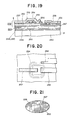
- FIG. 3 A main portion of Figure 3 is shown in an enlarged schematic view of Figure 18, and a second view of it at the portion of the recording magnetic head taken along the direction in which the head moves relative to the medium is shown in Figure 19.
- the recording and playback head will be described in connection with its process of fabrication.
- This head is joined to the substrate 221 having the recording and playback head mounted thereon such that the gap g of a thin-film magnetic recording head and one end of the optical waveguides of the optical playback head look out of the confronting plane 81, confronting the magneto-optical disc 31, on one side face of the slider 33.
- the substrate 221 is, for example, cut out from a monocrystalline Si wafer 230.
- a plurality of laminated members 227 of the thin-film magnetic recording head and the optical playback head are simultaneously formed within each of rectangular head forming areas 228, which are arranged into a plurality of vertical columns and a plurality of horizontal rows.
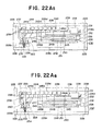
- FIG. 22A1 to 22A6 schematically show enlarged plan views of the principal portion at each step of the formation and Figures 22B1 to 22B4 shown sectional views taken along line B - B in Figures 22A1 to 22A4.
- first to third photodetector devices 231 to 233 are formed close to one short side 228a of each of the head forming areas 228 on the wafer 230 and fourth and fifth photodetector devices 234 and 235 are formed disposed in contact with and adjoining the long side 228c and closer to the short side 228b opposite to the short side 228a.
- These photodetector devices 231 to 235 are structured, for example, of a photodiode and all thereof are formed on the side of a principal plane 230a of the Si wafer 230 by a well-known technique.
- a surface insulating layer 236 of Si0 2 or the like by a method such as thermal oxidation of Si, and on this surface insulating layer 236, there are formed a required number of terminal areas 237 in an array towards the side of the other long side 228d for leading out external leads therefrom.
- a die bonding pad portion 238 for die bonding a later described semiconductor laser at the position close to and confronted with the first photodetector device 231, and in the vicinity of it, there is formed a wire bonding pad portion 239 used for wire bonding one of the electrodes of the semiconductor laser.
- wiring conductive layers 240 for connecting one of the electrodes of the first to fifth photodetector devices 231 to 235 to their corresponding terminal areas 237 and those for connecting the die bonding pad portion 238, the wire bonding pad portion 239, and so on to their corresponding terminal areas 237.
- Such terminal areas 237, bonding pad portions 238 and 239, and the wiring conductive layers 240 can be simultaneously formed into required patterns by deposition of AI or the like over the whole surface, through techniques such as metallic evaporation sputtering, or etching by photolithography.
- first and second inclined planes 241A and 241B whose one ends are located at a position opposing the second and third photodetector devices 232 and 233 and stretched therefrom along the length of the long sides 228C and 228d.
- These first and second inclined planes 241A and 241B are formed to be inclined by 45° or so.
- These first and second inclined planes 241A and 241 B can be formed, for example, by anisotropic etching of a monocrystalline silicon wafer 230.
- the planes which give the maximum value of the etching rate are the crystal planes (110), and those which give the minimum value are the crystal planes (111).
- an Si monocrystalline substrate 301 cut out along its crystal plane (100) is subjected to etching with a pyrocatechol ethylene diamine solution of aqueous solution of KOH using an etching mask 307 formed, for example, of Si0 2 and having a window 307a of a slit form elongated along the axis ⁇ 100> (in the direction perpendicular to the drawing in Figure 27A)
- an etching groove 308 of a triangular section as shown in Figure 27A is made, so that inclined planes 302A and 302B which are exposed crystal planes (111) each thereof forming an angle 0 1 of 54.74° with the surface of the substrate 301 are obtained on
- an Si monocrystalline substrate 301 having the crystal plane (110) lying along the surface of the substrate 301 is subjected to similar anisotropic etching using an SiO 2 etching resist 307 having a window 307a of a slit form elongated along the axis ⁇ 110>, then, according to selection of the width of the window 307a and the etching depth, an etching groove 308 with the crystal plane (110) exposed on the bottom face and the crystal plane (111) and ( 111 ) exposed on both sides thereof is made, whereby inclined planes 302A and 302B each thereof forming an angle 0 2 of 35.26° with the surface of the substrate 301 are obtained.
- a GaAs substrate can also be employed making use of its anisotropic property exhibited in etching with a Br 2 methanol group etchant, in which the maximum etching rate is exhibited in the direction of the axis ⁇ 110> and the minimum rate is exhibited in the direction of the axis ⁇ 111 > .
- a substrate having the crystal plane (100) and forming the etching pattern in the direction of the axis ⁇ 110> it is possible to obtain a groove with the first and second inclined planes provided on the crystal planes 111 forming an angle of about 45° with the surface of the substrate 301.
- a wafer with its surface taken along the crystal plane (100) is used as the monocrystalline Si wafer 230 and the direction along the long side fo the area 228 is selected to be in the direction of the axis ⁇ 100> .
- An insulating layer 242 of Si0 2 or the like is formed all over the surface of the wafer 230 by chemical vapour deposition or the like, and an elongated window 242A is made in this insulating layer 242 along the axis ⁇ 110> by a photolithographic technique or the like.
- an etchant such as KOH or a mixed solution of pyrocatechol and ethylene diamine. Then, since the crystal planes 110 exhibit the maximum etching rate and the planes (111) formed on both side faces thereof.
- the optical waveguide layer 223 is made up of a first optical waveguide 244, which is, first stretched from the midpoint between the fourth and fifth photodetector devices 234 and 235 in the direction parallel to the short side up to a bent portion, and then, stretched in the direction parallel to the long side until its end is led into a die bonding pad portion 238, and a second optical waveguide 245, of which one portion is a trunk 245C, one end thereof being located in the vicinity of or in contact with the end of the first optical waveguide 244 located between the photodetector devices 234 and 235, is similarly stretched in the direction parallel to the short side up to a bent portion, and stretched therefrom in the direction parallel to the long side to a point, where branches 245A and 245B are branched from the trunk, making a Y-shape, and these branches are stretched along the inclined planes 241A and 241
- the optical waveguides 244 and 245 are formed, for example, by depositing an optical waveguide forming thin-film layer of soda glass or the like all over the wafer 230 including the interior of the groove 243 to a thickness of 5 to 10 ⁇ m, and then, by applying selective ion exchanging, for example, of K + for Na + in the soda glass at the portion of the layer where the optical waveguides 244 and 245 are to be formed, from the surface to a required depth, thereby providing the portion with higher refractive index.
- Such a process to form optical waveguides by ion exchanging is carried out, although not shown, by coating the entire surface with a high temperature resistant mask of polyimide or the like, further coating the surface with a film of SiO 2 or the like serving as a resist to reactive ion etching (RIE), making a window having a pattern of the optical waveguides 244 and 245 in the film with a photoresist, opening windows with RIE through the resist mask of Si0 2 or the like and the material layer thereunder of polyimide or the like, and then dipping the wafer 230 in a molten liquid of KN0 3 .
- RIE reactive ion etching
- optical waveguides can be formed by carrying out selective ion implantation and diffusion as required, thereby providing the portion with a higher refractive index. Or, otherwise, by forming a thin film having a higher refractive index on the wafer 230 with a buffer layer of Si0 2 or the like interposed therebetween, and etching the film of high refractive index into a desired pattern by a photolithographic technique, ridge type optical waveguides formed of the film of high refractive index can be obtained. As shown in Figures 22A4 and 22B4, the above described polyamide used as the mask for the ion exchanging of the surface of Si0 2 thereon used as the etching resist, etc.
- a buffer layer 247 of Si0 2 or the like is formed all over the optical waveguide layer 223, that is, the optical waveguides 244 and 245, by sputtering or the like, and over the same, across the first optical waveguide 244 formed on the principal plane of the wafer 230 as well as the branches 245A and 245B of the second optical waveguide 245 formed on both the inclined planes 241A and 241B in the groove 243, a conductive layer 248 of a metallic layer of AI or the like or an amorphous Si layer or the like is formed by full-evaporation by CVD or the like and patterning by photolithography, or the like.
- a thin-film layer 222 constituting a recording magnetic head is formed between the fourth and fifth photodetector devices 234 and 235 over the end of the optical waveguide layer 223 constituting the optical playback head, or, in concrete terms, over the ends of the optical waveguides 244 and 245 for light beams. That is, a first magnetic thin film 252 is formed in a band form parallel to the short side of the area 228, and over the same, a head coil 254 of a conductive layer magnetic head in, for example a spiral pattern is formed by patterning by metallic layer evaporation and photolithography, or the like, with an interlayer insulating layer 253 of Si0 2 or the like interposed therebetween.
- FIG. 20 shows an enlarged plan view of the magnetic head portion.
- contact windows While making contact windows by selective etching in the insulating layers covering the terminal areas 237 as well as the pad portions 238 and 239 so that they are exposed to the outside, contact windows for exposing both ends of the coil 254 are made, and wiring conductive layers 258 are formed, through the contact windows, between the ends of the coil 254 and the corresponding terminal areas 237, and thereby electrical leading out of the coil terminals is achieved.
- prisms 259 and 260 by selectively etching the laminated insulating layer, buffer layer, or the like, so that prisms of an air layer are formed therein, or, as required, by burying a material with a low refractive index therein.
- a slider substrate 271 a ceramic substrate of Ti-Ca, Ti-Ba, AITiC, ferrite, or the like, to be finally turned into sliders 31 as shown in Figure 23A is first prepared.
- the principal plane of the substrate is finished to provide a smooth surface, and onto this surface, a wafer, for example, a monocrystalline wafer 230, having a plurality of the above described head assemblies thereon as shown in Figure 23B, is adhered by adhesive, glass bonding, molten metal bonding, or the like, whereby a joined member 272 is obtained.
- a wafer for example, a monocrystalline wafer 230, having a plurality of the above described head assemblies thereon as shown in Figure 23B, is adhered by adhesive, glass bonding, molten metal bonding, or the like, whereby a joined member 272 is obtained.
- the joined member 272 including the head forming areas 228 having head assemblies therein of the silicon wafer 230, is separated by, for example, being cut along the boundaries between the rows in the longitudinal direction as shown in Figure 23C, so that blocks 273 each thereof having integrated plural sets of the head portion and slider portion are obtained.
- the portions of the block 273 between the grooves 274 on the side opposite to the side where the wafer 230 is joined are provided with a taper 275 by being cut and ground.
- the block 273 is chip cut into a division having one area 228 of the wafer 230, whereby the substrate 221 having the head assembly is cut out together with the slider 31 to provide a slider member 276 being, for example, 3 mm wide and 1 mm high.
- the side of the long side 228C of the slider member 276 is ground so that it is formed into the confronting surface 81 to confront the magnetic recording medium.
- a semiconductor laser 277 is bonded onto the die bonding pad portion 238 for the laser diode and one electrode of the laser diode 277 is bonded using a wire lead 278 to the wire bonding pad portion 239.
- the attached portion of the semiconductor laser is sealed with a resin, and the member is arranged at the free end of the resilient member 25 of the gimbal mechanism described in Figure 3.
- a metallic plate 62 having a protrusion 61 on its top surface, for example, is attached to the slider member 276 so that the free end of the resilient plate 25 comes into abutment with the protrusion 61 allowing the slider member 276 to swing about the resilient plate 25.
- the terminal areas re soldered with external leads, for example, corresponding wires of a flexible substrate 79. In this way, the head apparatus can be constructed.
- the terminals on the ground side of the apparatus of the first to fifth photodetector devices 231 to 235 and the semiconductor laser 277 are brought in common on the side of the substrate 221 (Si wafer 230) and the terminal lead is taken out from one terminal area 237 in contact with the substrate 221.
- Outputs of the second and third photodetector devices 232 and 233 are supplied to a differential amplifier 135, and a differential output is derived.
- the semiconductor laser 277 in order that its light emitting end, that is, the end plane of its active layer, looks straight at the light inlet end of the first optical waveguide 244, provision is made, for example, to make a recess for its setting portion in the silicon wafer 230, or to adjust the thickness of the die bonding pad portion 238.
- the first photodetector device 231 is placed, for example, in a relative position with the semiconductor laser 277 such that it can effectively receive a beam of light which is similarly emitted from the semiconductor laser 277 facing the first optical waveguide 244, and the semiconductor laser 277 is arranged to be controlled for its power by the first photodetector devices 231.
- the fourth and fifth photodetector devices 234 and 235 having their front ends looking out of the confronting surface 281 confronting the magnetic recording medium are arranged to receive reflected beams from track guide grooves (not shown) formed on the magneto-optical recording medium 31 for taking out a differential output thereof, thereby to perform tracking servo.
- the first mode filter 249 is formed, for example, to lie along the surface of the substrate 221, whereby its plane of polarization is arranged at an angle of 90° with the centre plane between the inclined planes 241A and 241 B for the second and third mode filters 250 and 251, that is, the centre of the planes of polarization of the second and third mode filters 250 and 251.
- the magnetic recording and optical playback head constructed integrally with the slider member 276 disposed at the free end of the gimbal, that is, the resilient member 25, as described above, performs recording and playback in its floated state caused by an air flow produced by the relative movement of it with the magnetic recording medium 31, for example, a magneto-optical disc, as shown in Figure 3.
- magnetic recording in a magnetic recording medium is executed by an operation to be ordinarily performed by an induction-type head, that is, by being supplied with a signal current through the coil 254 of the thin-film magnetic head.
- light from the semiconductor laser 277 is introduced into the first optical waveguide 244 and passed through the first clad type mode filter 249, so that the light is turned into polarized light having a plane of polarization in a predetermined direction to be thrown on a recording track of the magnetic recording medium 31.
- Reflected light in which the plane of polarization has experienced a rotation by the magneto-optical interaction corresponding to the magnetically recorded information along the track is introduced into the trunk 245c of the optical waveguide 245.
- the output of the differential amplifier 135 will become, for example, zero upon receipt of the beams of light passed through the clad type mode filters 250 and 251 for the first and second branches 244A and 244B of the optical waveguide 244 into which the reflected light was introduced, then, when information "1" is read and therefore the reflected light experiences a Kerr rotation, one of the transmitted light quantities will increase while the other decreases, because the planes of polarization of both the second and third mode filters 250 and 251 are controlled by the inclined planes 241A and 241 B in the opposite directions with respect to the plane at an angle of 90° with the plane of polarization of the clad type mode filter 249 for the first optical waveguide 244, and thus, a large output can be taken out of the differential amplifier 135.
- the laser beam spot on the recording track is arranged to be an elongated spot having its major axis in the direction of the width of the track as described in Figure 24.
- Figures 24 and 25A both schematically show the pattern of the information bits formed by magnetization along the recording track on the magnetic recording medium, and the track width W is, for example, 1 to 2 1 1m and the bit length L B is 0.5 to 1 J.Lm
- the relative spot of irradiation beam is made, as shown by the solid line a, to have a length ( PL in the major axis, corresponding to the track width Tw, in the lateral direction to the track, and a length (ps in the minor axis in the direction longitudinal to the track.
- the spot is selected to be a virtually perfect circular shape as described above.
- the spot diameter is made to be as large as corresponding to the track width T w as shown by the broken line b in Figure 25A, the spot falls on adjoining bits, so that the output waveform exhibits a rounding as shown by the broken line b in Figure 25B and the S/N ratio is deteriorated especially in the short-wave range.
- the spot diameter is made small as shown by the broken line c in Figure 25A, while the S/N ratio is improved, the output is lowered as shown by the broken line c in Figure 25B because the radiation of light is made only on a part of the bit.
- the beam spot is made into an elongated spot a as described above, the lowering of the output can be suppressed as shown by the solid line a in Figure 25B and the S/N ratio in the short-wave range can be improved.
- the curves 291a, 291b and 291c in Figure 26 shown frequency characteristics of the spots a, b and c described in Figure 25.
- the spot in an elongated shape is used as described above, it is desired to arrange the first optical waveguide 244 to be able to propagate a basic wave mode, so that separation of the spot may be prevented from occurring and a single spot may be obtained.
- the optical playback head of the present invention the optical system has been made smaller by the use of the optical waveguides instead of a conventional large lens system, and for the head for use with magneto-optical discs, the polarizer and analyzer have been arranged by the use of metal-clad mode filters, and hence, the head can be formed on a light-weight slider.
- the polarizer and analyzer have been arranged by the use of metal-clad mode filters, and hence, the head can be formed on a light-weight slider.
- the metal-clad mode filters are provided for the first and second optical waveguides and they are arranged to form an angle of 45° or a predetermined angle close to 45° with each other, the playback signal from a magneto-optical disc can be maximized.
- the ends of the first and second optical waveguides are disposed adjacent to each other and the sectional area of one end of the second waveguide is formed to be larger than the sectional area of one end of the first optical waveguide, it is possible effectively to collect the reflected light from a recording medium through the end of the second optical waveguide and thereby to enhance the playback output greatly.
- the sectional area of one end of the first optical waveguide is formed to be small, the return light of the reflected light to the first optical waveguide is limited, whereby unstable oscillation of the laser diode is prevented.
- the sectional area of one end of the first optical waveguide is made small, formation of narrower recording tracks can be attained. Moreover, since the optical system can be made smaller by the use of the optical waveguides instead of a large lens system, the pick-up can be formed on a light-weight slider and high-speed access can thereby be attained.
- the positioning of both the heads can be carried out accurately, and since the thin-film technique capable of forming the film with high precision is used, the positioning can be made more accurate, and mass production with good reproducibility can be attained. Further, since the device can be structured in small size and light weight, the head as a whole can be light. Hence, high-speed access can be attained.
- the optical waveguides of the optical waveguides 244 and 245 are all provided with mode filters 249, 250 and 251 in their midpoints, and this means that such a structure generally requires considerably dimensions.
- the prisms 259 and 260 it is possible to stretch the waveguides 244 and 245 not only in the direction of the height of the slider 33, but also in the direction turned from that direction parallel to the magnetic recording medium 31.
- the need for holding the slider 33 high, and hence, the need for keeping the point of support of the gimbal, that is, the resilient member 25 high is eliminated, and thus, it is possible to overcome the structural disadvantage involved therein.
- the output from the optical playback head is taken out as a differential value of the outputs from both the branches 245A and 245B, an increased output level is obtained and the noise components being in phase are cancelled by each other, so an improved S/N ratio can be achieved.
- first and second branches 245A and 245B and the mode filters 250 and 251 must be provided, the branches 245A and 245B together with the first optical waveguide 244 are stretched in the two directions relative to the magnetic recording medium 31 as described above.
- the fabrication can be made easier and the structure can be made simpler.
Landscapes
- Physics & Mathematics (AREA)
- Optics & Photonics (AREA)
- Engineering & Computer Science (AREA)
- Manufacturing & Machinery (AREA)
- Optical Integrated Circuits (AREA)
- Optical Head (AREA)
Applications Claiming Priority (10)
| Application Number | Priority Date | Filing Date | Title |
|---|---|---|---|
| JP99380/88 | 1988-04-22 | ||
| JP63099380A JPH01271931A (ja) | 1988-04-22 | 1988-04-22 | 光学的再生ヘッド |
| JP102300/88 | 1988-04-25 | ||
| JP63102300A JP2629812B2 (ja) | 1988-04-25 | 1988-04-25 | 光再生ピックアップ |
| JP243340/88 | 1988-09-28 | ||
| JP63243340A JPH0291831A (ja) | 1988-09-28 | 1988-09-28 | 光再生ピックアップ |
| JP275322/88 | 1988-10-31 | ||
| JP63275322A JPH02122449A (ja) | 1988-10-31 | 1988-10-31 | 偏光面検出装置 |
| JP63275330A JP2907431B2 (ja) | 1988-10-31 | 1988-10-31 | 光磁気ヘッド装置 |
| JP275330/88 | 1988-10-31 |
Publications (3)
| Publication Number | Publication Date |
|---|---|
| EP0338864A2 true EP0338864A2 (de) | 1989-10-25 |
| EP0338864A3 EP0338864A3 (en) | 1990-11-28 |
| EP0338864B1 EP0338864B1 (de) | 1993-11-10 |
Family
ID=27525959
Family Applications (1)
| Application Number | Title | Priority Date | Filing Date |
|---|---|---|---|
| EP89304020A Expired - Lifetime EP0338864B1 (de) | 1988-04-22 | 1989-04-21 | Magneto-optische Wiedergabeköpfe |
Country Status (4)
| Country | Link |
|---|---|
| US (1) | US5065390A (de) |
| EP (1) | EP0338864B1 (de) |
| KR (1) | KR970008229B1 (de) |
| DE (1) | DE68910570T2 (de) |
Cited By (7)
| Publication number | Priority date | Publication date | Assignee | Title |
|---|---|---|---|---|
| EP0345232A3 (de) * | 1988-05-31 | 1991-07-31 | Nikon Corporation | Integriertes optisches Gerät für magneto-optischen Aufnahme- und Wiedergabekopf |
| EP0446063A1 (de) * | 1990-03-08 | 1991-09-11 | Pioneer Electronic Corporation | Aufzeichnungsträger und Wiedergabegerät zum Wiedergeben desselben |
| EP0474433A1 (de) * | 1990-09-05 | 1992-03-11 | Canon Kabushiki Kaisha | Vorrichtung und Verfahren zur Informationsverarbeitung |
| EP0512915A1 (de) * | 1991-05-07 | 1992-11-11 | Commissariat A L'energie Atomique | Integrierter magnetooptischer Lese- und Schreibkopf und Herstellungsverfahren |
| US5289454A (en) * | 1991-12-19 | 1994-02-22 | Minnesota Mining And Manufacturing Company | Optical disc addressing devices a method of use thereof |
| WO2004068206A1 (ja) * | 2003-01-30 | 2004-08-12 | Sony Corporation | 光導波路および光送受信モジュール |
| EP2026333A1 (de) * | 2007-07-31 | 2009-02-18 | Nitto Denko Corporation | Aufhängungsplatte mit Schaltung |
Families Citing this family (17)
| Publication number | Priority date | Publication date | Assignee | Title |
|---|---|---|---|---|
| JPH04301245A (ja) * | 1991-03-28 | 1992-10-23 | Canon Inc | 光磁気記録再生用光ヘッド |
| US5504722A (en) * | 1993-01-27 | 1996-04-02 | Nippon Telegraph And Telephone Corporation | Magneto-optic information storage system utilizing a TE/TM mode controlling laser diode |
| JP2765793B2 (ja) * | 1993-03-16 | 1998-06-18 | シャープ株式会社 | モード分離素子および光磁気ディスク用ピックアップ |
| US6181673B1 (en) * | 1996-07-30 | 2001-01-30 | Read-Rite Corporation | Slider design |
| US5859814A (en) * | 1996-10-18 | 1999-01-12 | The Board Of Trustees Of The Leland Stanford Junior University | Magneto-optic recording system and method |
| US5874939A (en) * | 1996-12-10 | 1999-02-23 | Motorola, Inc. | Keyboard apparatus and method with voice recognition |
| WO1998052193A1 (en) * | 1997-05-15 | 1998-11-19 | Seagate Technology, Inc. | Optical disc data storage system using optical waveguide |
| JP4290279B2 (ja) * | 1999-06-04 | 2009-07-01 | 独立行政法人産業技術総合研究所 | 光学試料体並びにその書込みおよび読出し方法 |
| US6762977B1 (en) * | 1999-09-13 | 2004-07-13 | Seagate Technology Llc | Laser assisted magnetic recording apparatus and method |
| JP4019615B2 (ja) * | 2000-03-10 | 2007-12-12 | 富士ゼロックス株式会社 | 光磁気素子、光磁気ヘッドおよび磁気ディスク装置 |
| JP2001332799A (ja) * | 2000-05-19 | 2001-11-30 | Rohm Co Ltd | モールド型半導体レーザ |
| US6717893B1 (en) * | 2000-10-04 | 2004-04-06 | Dphi Acquisitions, Inc. | Laser thermal management system |
| US6629077B1 (en) | 2000-11-22 | 2003-09-30 | Universal Electronics Inc. | Universal remote control adapted to receive voice input |
| US7869309B2 (en) * | 2005-08-11 | 2011-01-11 | Seagate Technology Llc | Dual wire integrated WAMR/HAMR writing head |
| JPWO2007132766A1 (ja) * | 2006-05-16 | 2009-09-24 | コニカミノルタオプト株式会社 | 光記録ヘッド、光磁気記録ヘッド及び光記録装置 |
| US8270257B2 (en) * | 2008-01-31 | 2012-09-18 | Hitachi Global Storage Technologies Netherlands B.V. | Thermally assisted recording systems with low loss light redirection structure |
| WO2017031366A1 (en) * | 2015-08-19 | 2017-02-23 | President And Fellows Of Harvard College | Broadband multifunctional efficient meta-gratings based on dielectric waveguide phase shifters |
Family Cites Families (6)
| Publication number | Priority date | Publication date | Assignee | Title |
|---|---|---|---|---|
| US4220395A (en) * | 1974-05-13 | 1980-09-02 | Regents Of University Of California | Polarization converter and circuit elements for use in optical waveguides |
| US4737946A (en) * | 1984-09-03 | 1988-04-12 | Omron Tateisi Electronics Co. | Device for processing optical data with improved optical allignment means |
| JPS61188748A (ja) * | 1985-02-16 | 1986-08-22 | Brother Ind Ltd | 光学ヘツド |
| US4779259A (en) * | 1985-04-25 | 1988-10-18 | Mitsubishi Denki Kabushiki Kaisha | Optical head assembly with efficient light source coupling surface and method of construction |
| JP2539406B2 (ja) * | 1987-02-04 | 1996-10-02 | 株式会社日立製作所 | 固体光ピツクアツプ |
| US4945525A (en) * | 1987-09-04 | 1990-07-31 | Sharp Kabushiki Kaisha | Optical information processing apparatus |
-
1989
- 1989-04-20 US US07/341,115 patent/US5065390A/en not_active Expired - Fee Related
- 1989-04-21 DE DE89304020T patent/DE68910570T2/de not_active Expired - Fee Related
- 1989-04-21 KR KR1019890005257A patent/KR970008229B1/ko not_active Expired - Lifetime
- 1989-04-21 EP EP89304020A patent/EP0338864B1/de not_active Expired - Lifetime
Cited By (14)
| Publication number | Priority date | Publication date | Assignee | Title |
|---|---|---|---|---|
| EP0345232A3 (de) * | 1988-05-31 | 1991-07-31 | Nikon Corporation | Integriertes optisches Gerät für magneto-optischen Aufnahme- und Wiedergabekopf |
| US5218594A (en) * | 1990-03-08 | 1993-06-08 | Pioneer Electric Corporation | Recording medium with an optical waveguide and player for playing the same |
| EP0446063A1 (de) * | 1990-03-08 | 1991-09-11 | Pioneer Electronic Corporation | Aufzeichnungsträger und Wiedergabegerät zum Wiedergeben desselben |
| US5448421A (en) * | 1990-09-05 | 1995-09-05 | Canon Kabushiki Kaisha | Method for positioning an information processing head by detecting a magnetization pattern on a magnetic material positioned relative to a recording medium and a process for forming a recording and/or reproducing cantilever type probe |
| US5278704A (en) * | 1990-09-05 | 1994-01-11 | Canon Kabushiki Kaisha | Information processing apparatus including magnetic material having a predetermined magnetization pattern with respect to a recording medium |
| EP0474433A1 (de) * | 1990-09-05 | 1992-03-11 | Canon Kabushiki Kaisha | Vorrichtung und Verfahren zur Informationsverarbeitung |
| FR2676303A1 (fr) * | 1991-05-07 | 1992-11-13 | Commissariat Energie Atomique | Tete magneto-optique integree de lecture et d'ecriture et procede de realisation. |
| EP0512915A1 (de) * | 1991-05-07 | 1992-11-11 | Commissariat A L'energie Atomique | Integrierter magnetooptischer Lese- und Schreibkopf und Herstellungsverfahren |
| US5317800A (en) * | 1991-05-07 | 1994-06-07 | Commissariat A L'energie Atomique | Method of making an integrated magnetooptical read and write head |
| US5289454A (en) * | 1991-12-19 | 1994-02-22 | Minnesota Mining And Manufacturing Company | Optical disc addressing devices a method of use thereof |
| EP0784314A1 (de) | 1991-12-19 | 1997-07-16 | Minnesota Mining And Manufacturing Company | Vorrichtung zur Adressierung einer optischen Platte |
| WO2004068206A1 (ja) * | 2003-01-30 | 2004-08-12 | Sony Corporation | 光導波路および光送受信モジュール |
| US7260295B2 (en) | 2003-01-30 | 2007-08-21 | Sony Corporation | Optical waveguide and optical transmitting/receiving module |
| EP2026333A1 (de) * | 2007-07-31 | 2009-02-18 | Nitto Denko Corporation | Aufhängungsplatte mit Schaltung |
Also Published As
| Publication number | Publication date |
|---|---|
| EP0338864A3 (en) | 1990-11-28 |
| US5065390A (en) | 1991-11-12 |
| KR900016967A (ko) | 1990-11-15 |
| EP0338864B1 (de) | 1993-11-10 |
| KR970008229B1 (ko) | 1997-05-22 |
| DE68910570T2 (de) | 1994-02-24 |
| DE68910570D1 (de) | 1993-12-16 |
Similar Documents
| Publication | Publication Date | Title |
|---|---|---|
| EP0338864B1 (de) | Magneto-optische Wiedergabeköpfe | |
| US5199090A (en) | Flying magnetooptical read/write head employing an optical integrated circuit waveguide | |
| US4876680A (en) | Monolithic optical pick-up using an optical waveguide | |
| US5995474A (en) | Flying type optical head integrally formed with light source and photodetector and optical disk apparatus with the same | |
| EP0917713B1 (de) | Magnetooptisches aufzeichnungssystem mit nahfeldoptik | |
| KR19980702610A (ko) | 적층형 근접장 광헤드 및 광정보기록재생장치 | |
| JPH07287883A (ja) | 光集積回路 | |
| US3877784A (en) | Beam address optical storage head | |
| US5166989A (en) | Integrated polarization detection system | |
| JPH01271931A (ja) | 光学的再生ヘッド | |
| JP2577726B2 (ja) | 光磁気ヘツド | |
| JPH0355894B2 (de) | ||
| JPH02122452A (ja) | 浮上型光再生ヘッド装置の製法 | |
| JP2907431B2 (ja) | 光磁気ヘッド装置 | |
| JPH02122450A (ja) | 磁気記録光再生ヘッド装置 | |
| JPS6139956A (ja) | 磁気−光ヘツド | |
| JP2682052B2 (ja) | 光学ヘッド | |
| JP2629812B2 (ja) | 光再生ピックアップ | |
| JPH01286155A (ja) | 光磁気情報記録再生装置 | |
| JPH01298552A (ja) | 光磁気情報記録再生装置 | |
| JPH02122451A (ja) | 光再生ヘッド装置 | |
| Renard et al. | Magneto-optical reading and writing integrated heads: a way to a multigigabyte multi-rigid-disk drive | |
| JPH01271946A (ja) | 磁気光再生ヘッド | |
| Minami et al. | OPTICAL WAVEGUIDE DEVICE FOR A MAGNETO-OPTICAL DISK HEAD | |
| JPH0495252A (ja) | 光学読取装置 |
Legal Events
| Date | Code | Title | Description |
|---|---|---|---|
| PUAI | Public reference made under article 153(3) epc to a published international application that has entered the european phase |
Free format text: ORIGINAL CODE: 0009012 |
|
| AK | Designated contracting states |
Kind code of ref document: A2 Designated state(s): DE FR GB NL |
|
| PUAL | Search report despatched |
Free format text: ORIGINAL CODE: 0009013 |
|
| AK | Designated contracting states |
Kind code of ref document: A3 Designated state(s): DE FR GB NL |
|
| 17P | Request for examination filed |
Effective date: 19910326 |
|
| 17Q | First examination report despatched |
Effective date: 19930128 |
|
| GRAA | (expected) grant |
Free format text: ORIGINAL CODE: 0009210 |
|
| AK | Designated contracting states |
Kind code of ref document: B1 Designated state(s): DE FR GB NL |
|
| REF | Corresponds to: |
Ref document number: 68910570 Country of ref document: DE Date of ref document: 19931216 |
|
| ET | Fr: translation filed | ||
| PLBE | No opposition filed within time limit |
Free format text: ORIGINAL CODE: 0009261 |
|
| STAA | Information on the status of an ep patent application or granted ep patent |
Free format text: STATUS: NO OPPOSITION FILED WITHIN TIME LIMIT |
|
| 26N | No opposition filed | ||
| PGFP | Annual fee paid to national office [announced via postgrant information from national office to epo] |
Ref country code: GB Payment date: 19950410 Year of fee payment: 7 |
|
| PGFP | Annual fee paid to national office [announced via postgrant information from national office to epo] |
Ref country code: FR Payment date: 19950411 Year of fee payment: 7 |
|
| PGFP | Annual fee paid to national office [announced via postgrant information from national office to epo] |
Ref country code: DE Payment date: 19950421 Year of fee payment: 7 |
|
| PGFP | Annual fee paid to national office [announced via postgrant information from national office to epo] |
Ref country code: NL Payment date: 19950430 Year of fee payment: 7 |
|
| PG25 | Lapsed in a contracting state [announced via postgrant information from national office to epo] |
Ref country code: GB Effective date: 19960421 |
|
| PG25 | Lapsed in a contracting state [announced via postgrant information from national office to epo] |
Ref country code: NL Effective date: 19961101 |
|
| GBPC | Gb: european patent ceased through non-payment of renewal fee |
Effective date: 19960421 |
|
| PG25 | Lapsed in a contracting state [announced via postgrant information from national office to epo] |
Ref country code: FR Effective date: 19961227 |
|
| PG25 | Lapsed in a contracting state [announced via postgrant information from national office to epo] |
Ref country code: DE Effective date: 19970101 |
|
| NLV4 | Nl: lapsed or anulled due to non-payment of the annual fee |
Effective date: 19961101 |
|
| REG | Reference to a national code |
Ref country code: FR Ref legal event code: ST |