EP0337519A2 - Procédé et dispositif de protection et de support d'un joint d'étanchéité d'une vanne - Google Patents
Procédé et dispositif de protection et de support d'un joint d'étanchéité d'une vanne Download PDFInfo
- Publication number
- EP0337519A2 EP0337519A2 EP19890200512 EP89200512A EP0337519A2 EP 0337519 A2 EP0337519 A2 EP 0337519A2 EP 19890200512 EP19890200512 EP 19890200512 EP 89200512 A EP89200512 A EP 89200512A EP 0337519 A2 EP0337519 A2 EP 0337519A2
- Authority
- EP
- European Patent Office
- Prior art keywords
- seal
- valve device
- closure part
- valve
- closed position
- Prior art date
- Legal status (The legal status is an assumption and is not a legal conclusion. Google has not performed a legal analysis and makes no representation as to the accuracy of the status listed.)
- Pending
Links
- 238000000034 method Methods 0.000 title claims abstract description 13
- 238000007789 sealing Methods 0.000 claims abstract description 27
- 230000000694 effects Effects 0.000 claims abstract description 3
- 239000012459 cleaning agent Substances 0.000 claims description 11
- 239000012530 fluid Substances 0.000 claims description 10
- 230000009471 action Effects 0.000 claims description 2
- 238000005516 engineering process Methods 0.000 abstract description 2
- 230000008569 process Effects 0.000 abstract description 2
- 238000004140 cleaning Methods 0.000 description 15
- 239000000243 solution Substances 0.000 description 6
- 230000003993 interaction Effects 0.000 description 5
- 239000007788 liquid Substances 0.000 description 4
- 230000008901 benefit Effects 0.000 description 3
- 238000005507 spraying Methods 0.000 description 3
- 238000009434 installation Methods 0.000 description 2
- 238000005192 partition Methods 0.000 description 2
- 238000006467 substitution reaction Methods 0.000 description 2
- 238000005260 corrosion Methods 0.000 description 1
- 230000007797 corrosion Effects 0.000 description 1
- 230000003628 erosive effect Effects 0.000 description 1
- 230000003014 reinforcing effect Effects 0.000 description 1
- 239000012086 standard solution Substances 0.000 description 1
Images

Classifications
-
- F—MECHANICAL ENGINEERING; LIGHTING; HEATING; WEAPONS; BLASTING
- F16—ENGINEERING ELEMENTS AND UNITS; GENERAL MEASURES FOR PRODUCING AND MAINTAINING EFFECTIVE FUNCTIONING OF MACHINES OR INSTALLATIONS; THERMAL INSULATION IN GENERAL
- F16K—VALVES; TAPS; COCKS; ACTUATING-FLOATS; DEVICES FOR VENTING OR AERATING
- F16K3/00—Gate valves or sliding valves, i.e. cut-off apparatus with closing members having a sliding movement along the seat for opening and closing
- F16K3/22—Gate valves or sliding valves, i.e. cut-off apparatus with closing members having a sliding movement along the seat for opening and closing with sealing faces shaped as surfaces of solids of revolution
- F16K3/24—Gate valves or sliding valves, i.e. cut-off apparatus with closing members having a sliding movement along the seat for opening and closing with sealing faces shaped as surfaces of solids of revolution with cylindrical valve members
- F16K3/243—Packings
-
- F—MECHANICAL ENGINEERING; LIGHTING; HEATING; WEAPONS; BLASTING
- F16—ENGINEERING ELEMENTS AND UNITS; GENERAL MEASURES FOR PRODUCING AND MAINTAINING EFFECTIVE FUNCTIONING OF MACHINES OR INSTALLATIONS; THERMAL INSULATION IN GENERAL
- F16K—VALVES; TAPS; COCKS; ACTUATING-FLOATS; DEVICES FOR VENTING OR AERATING
- F16K25/00—Details relating to contact between valve members and seats
-
- Y—GENERAL TAGGING OF NEW TECHNOLOGICAL DEVELOPMENTS; GENERAL TAGGING OF CROSS-SECTIONAL TECHNOLOGIES SPANNING OVER SEVERAL SECTIONS OF THE IPC; TECHNICAL SUBJECTS COVERED BY FORMER USPC CROSS-REFERENCE ART COLLECTIONS [XRACs] AND DIGESTS
- Y10—TECHNICAL SUBJECTS COVERED BY FORMER USPC
- Y10S—TECHNICAL SUBJECTS COVERED BY FORMER USPC CROSS-REFERENCE ART COLLECTIONS [XRACs] AND DIGESTS
- Y10S251/00—Valves and valve actuation
- Y10S251/90—Valves with o-rings
-
- Y—GENERAL TAGGING OF NEW TECHNOLOGICAL DEVELOPMENTS; GENERAL TAGGING OF CROSS-SECTIONAL TECHNOLOGIES SPANNING OVER SEVERAL SECTIONS OF THE IPC; TECHNICAL SUBJECTS COVERED BY FORMER USPC CROSS-REFERENCE ART COLLECTIONS [XRACs] AND DIGESTS
- Y10—TECHNICAL SUBJECTS COVERED BY FORMER USPC
- Y10T—TECHNICAL SUBJECTS COVERED BY FORMER US CLASSIFICATION
- Y10T137/00—Fluid handling
- Y10T137/4238—With cleaner, lubrication added to fluid or liquid sealing at valve interface
- Y10T137/4245—Cleaning or steam sterilizing
-
- Y—GENERAL TAGGING OF NEW TECHNOLOGICAL DEVELOPMENTS; GENERAL TAGGING OF CROSS-SECTIONAL TECHNOLOGIES SPANNING OVER SEVERAL SECTIONS OF THE IPC; TECHNICAL SUBJECTS COVERED BY FORMER USPC CROSS-REFERENCE ART COLLECTIONS [XRACs] AND DIGESTS
- Y10—TECHNICAL SUBJECTS COVERED BY FORMER USPC
- Y10T—TECHNICAL SUBJECTS COVERED BY FORMER US CLASSIFICATION
- Y10T137/00—Fluid handling
- Y10T137/4238—With cleaner, lubrication added to fluid or liquid sealing at valve interface
- Y10T137/4358—Liquid supplied at valve interface
Definitions
- the invention relates to a method and a device for protecting and supporting a seal of a valve device according to the preamble of claim 1.
- a valve device of the type identified in the introduction is known from DE-A-37 01 027 and also from European patent application 02 79 177.
- the subject of the aforementioned patent applications is based on the respective preamble of the main claim of a valve with a leakage space, which is equipped with two sealing points, which are arranged in series and in the closed position of the valve prevent the overflow of fluids from one valve housing part into another.
- the two sealing points are realized, inter alia, by a seal arrangement with two seals which are separate from one another and arranged on the valve housing side, these two discrete seals being designed, inter alia, as seals with a circular cross section.
- the leakage space is arranged between the sealing points and is connected to the surroundings of the valve via the valve housing.
- the procedural task is solved, in addition to the control of the medium inlet from the interior of the valve to the leakage chamber, which is known per se in the closed position of the valve, of controlling this inlet also in other positions of the valve.
- the procedural problem is solved in that the medium entry from the interior to the leakage space in others Positions as in the closed position of the valve are operatively controlled in the same way as in the closed position by a provision substituting the closing member with regard to its interaction with the leakage space.
- a closure part which has an internal passage and which is arranged to be relatively movable in relation to the closing element in the direction of its degree of freedom of movement.
- the closure part is in permanent contact with the two sealing points or the two seals.
- the known closure part is always and in all applications to be seen in cooperation with two seals or sealing points and it controls, as intended, only the medium entry from the interior to the leakage space between the two seals or sealing points.
- the closure part takes over the protection and support of the two seals or sealing points in positions other than the closed position of the valve, if these are realized by means of sealing means arranged on the valve housing side.
- sealing means arranged on the valve housing side.
- the known closure part in its proposed arrangement and mode of operation, offers no protection and no support.
- valve device for performing the aforementioned method.
- a seal with a circular cross-section a so-called O-ring, which is a structurally simple, but in particular a not unproblematic sealing element when arranged on the valve housing side, with limited movement in a housing-side groove, since the valve is also in the open position this seal is fixed by the closure part in a position that is adequate to its position in the closed position of the valve. As a result, it is removed from the mechanical stress caused by the fluid even when the valve is open.
- the seal arranged on the housing side is completely open in the open position of the valve towards the interior of the valve housing. It is exposed to flow forces, corrosion and erosion of the fluid, at least on its surface facing the interior of the valve housing, without protection.
- Loose sealing arrangements cannot be satisfactorily solved with known means without special measures. Loose sealing arrangements of this type are, however, mandatory for biological and cleaning-related reasons, for example in the United States of America as standard solutions, where the problem there by accepting the mechanical instability of the seal described above or by reinforcing the seal or arranging it in a cage has so far been unsatisfactory Way is solved.
- the present invention solves the existing problem associated with the loosely arranged sealing ring with relatively simple means.
- the proposed invention also shows how the interaction principle known from the aforementioned patent applications between the closure part on the one hand and the valve housing, the two seals or sealing points and the leakage space on the other hand now analogously by means of an interaction principle between the closure part on the one hand and the closing member, the seal or the seals and possibly a leakage space on the other hand is replaced. It is achieved on the one hand that the closure part in other positions than in the closed position of the valve protects and supports a seal arranged on the closing member side or also two of them.
- the medium inlet from the interior to the leakage space is also effective in other positions than in the closed position of the valve in the same way as in the closed position by a substitution of the closing element with regard to its interaction with the leakage space Arrangement controlled.
- the interaction principle proposed according to the invention between the closure part and the closure member results in the closure member being wrapped around the closure part in the open position of the valve device, the feature of the mandatory so-called “inner passage” which is mandatory from the known valve devices is eliminated for the closure part.
- the closing part is now no longer flowed through by the fluid in the open position of the valve device.
- the seat area is no longer narrowed in terms of its passage cross section by the ring cross section of the closure part.
- Another advantage is the fact that the closure part is guided on or on the closing member with which it forms a pairing in the open position of the valve device.
- the closing part is also guided on or on the closing member, but the pairing is carried out with the seat area of the valve housing.
- the device according to the invention results in lower demands on the guiding quality or on an aligned arrangement between the closing member axis and the valve housing.
- Two seals arranged on the closing element side, between which a leakage space is arranged, which is connected via lines to the surroundings of the valve device, can be cleaned with the means known from the aforementioned patent applications, both in the closed and in the open position of the valve device.
- the cleaning of a single seal, which is arranged either on the valve housing side or on the closing member side and which is covered according to the invention in all positions of the valve with respect to the interior of the valve housing is provided according to an advantageous embodiment of the valve device according to the invention in that the closure part in the area of its overlap the seal is designed to be permeable from the interior of the valve housing to the seal. Since the closure part has no sealing function in this case, but is only intended to protect and support the seal in its position on the housing in the open position of the valve, it can be provided, for example, with a large number of openings.
- a further embodiment of the valve device according to the invention achieves the cleanability of the single seal from the interior of the valve housing part in that the closure part is dimensioned in the direction of its shifting mobility in such a way that there is a spatial connection between the interior of the valve housing and the walls surrounding the seal is.
- This dimensioning necessity which is caused by cleaning technology, leads to a very flat closure part.
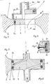
- FIG. 1 The aforementioned substitution principle of a closure part 5 and a seating area 3 of a valve housing 1, 2 with respect to a closing member 4 and its seal 7 can be seen from FIG.
- the closed position of the valve device is shown, with no illustration of the means for actuating the closing member 4 and the closure part 5.
- the seat area 3 interacts with the closing member 4 and its seal 7.
- the open position of the valve device illustratedration on the right
- the effect of the seat area 3 in relation to the seal 7 is substituted by the closure part 5.
- the stress on the seal 7 generated in the closed position of the valve device is caused in other positions than in the closed position by the closure part 5.
- valve device In the open position of the valve device, a throughflow V passes from the valve housing part 1 into the valve housing part 2 or vice versa.
- the closure part 5 has the same dimension D with respect to its bore receiving the closing member 4 as the connecting bore of the valve housing parts 1, 2 in its seating area 3.
- the schematically illustrated valve device is a shut-off valve with an open / close function.
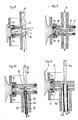
- the closing member 4 was modified from that according to FIG. 1 in such a way that two seals 71, 72 are now provided which accommodate a leakage space 6 between them.
- This leakage space 6 is bordered on the one hand by the valve housing part 1, 2 in the closed position of the valve device, and on the other hand it is connected to the surroundings of the valve device via a drain hole 6a, which is arranged within the closing element 4.
- a drain hole 6a which is arranged within the closing element 4.
- the drain hole 6a can be arranged in a drain pipe 4b, which is connected to the closing member 4 and led out of the valve housing part 2.
- the reversal is also conceivable in that the drain pipe 4b is arranged on the side of the valve housing part 1 and is led out of the latter into the surroundings of the valve.
- FIG. 2 shows the leak-proof valve device in its open position.
- the leakage space 6 is now bordered on the outside by the inner lateral surface of the closure part 5. Both in the closed and in the open position of the valve device, the leakage space 6 is closed off from the interior of the valve housing parts 1 and 2.
- closure part 5 replaces the seating area 3 of the valve housing parts 1 and 2 with respect to the seals 71 and 72 and with respect to the leakage space 6.
- a seat ring (not shown in FIG. 2) can be arranged in the seating area 3, which is equally equipped with the above-mentioned functions on the housing side.
- a so-called “loose” seal 7 is provided in the embodiment according to FIGS. 3 and 4, which is arranged within a groove 4c of the closing element 4.
- the seal 7 has a limited mobility within the groove 4c in the direction of the switching movement of the closing member 4, as a result of which the critical areas between the seal 7 and the groove 4c can be cleaned.
- cleaning of these areas presupposes that the closure part 5 is dimensioned such that there is a spatial connection between the interior of the valve housing parts 1, 2 and the walls surrounding the seal 7.
- FIGS. 5, 6 and 7 show a closing element 4 which, in accordance with the corresponding embodiment of the valve device according to FIG. 2, is equipped with two seals 71 and 72 which enclose a leakage space 6 between them.
- This leakage space 6 is not only connected to the surroundings of the valve device via a drain hole 6a, as shown in FIG. 2, but it also has a second connection path to the surroundings of the valve device, via which cleaning fluid can be introduced into the leakage space 6.
- the aforementioned type of leakage or cleaning agent discharge (denoted by L / R in FIGS. 5 and 6) and the cleaning agent supply R can also be applied to a sealing arrangement according to the embodiment according to FIG. 7, in which the two seals 71 and 72 have limited movement in the closing member 4 are arranged. Solutions in this regard can be found in DE-A-37 01 027 and EP-02 79 177.
- the closing member 4 can be designed as a hollow body between the seals 71 and 72 (FIG. 8), the cleaning liquid being supplied to the area of the seals 71 and 72 via a distribution and spraying device 8.
- the area between the seals 71 and 72 can also be divided by a partition 9 (FIG. 9), which forms a feed area 10 and a discharge area 11, so that the cleaning agent R is forcibly fed to the seal area and also removed from it.
- a partition 9 FIG. 9
- a cleaning pipe 12 with the distributing and spraying device 8 is arranged in the drain hole 6a of the drain pipe 4b.
- the cleaning liquid R is fed to the sealing area and is discharged from there via an annular gap 13, formed between the inner wall of the drain pipe 4b and the cleaning pipe 12.
- the embodiment according to FIG. 11 corresponds essentially to that according to FIG. 9, the inlet for the cleaning liquid R and the outlet for the leakage or cleaning liquid L / R being arranged on one side of the closing element 4.
- the closing member 4 is driven either via the first rod 4a, which is arranged on the side of the closing member 4 opposite the drain pipe 4b, and out of the valve housing part 1 is led out or, if the first rod 4a is dispensed with, via the drain pipe 4b, the installation position of the valve device, as shown in FIG. 11, being present, or an installation position chosen by 180 ° with respect to the arrangement shown.
- valve device according to the invention shown in FIGS. 2 and 5 to 11 are each a so-called leak-free switching double-seat valve. If the closure part 5 is fixedly connected to the valve housing part 1 or 2 via webs, a valve device results with which leakage-limited switching is possible.
- the connecting webs between the closure part 5 and the valve housing part 1 or 2 are to be provided with through openings which correspond approximately to the nominal cross section of the valve. Operation and function of this arrangement are known from the aforementioned patent applications. Here there is an imperative analogy that arises from the various aspects and considerations of the present problem.
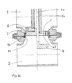
- FIG. 12 shows a valve device according to the invention, which represents the principle of operation of the closure part 5 on which the present invention is based, compared to a seal 7 on the housing, using the simplest switching function, the open / close function.
- the left-hand representation shows the closed position of the valve device, the right-hand side shows its open position.
- the seal 7, which is embedded in a housing groove 1 a with axial play is in a manner known per se by the closing member 4 fixed.
- the housing seal 14 necessary between the valve housing parts 1 and 2 has been shown in a very simplified manner with regard to its arrangement and embedding.
- the closure part 5 can be provided with a multiplicity of openings so that it has the shape of a cage, for example.
- recesses which are continuous from the end face of the closure part 5 and which allow the access of cleaning fluid between the outer lateral surface of the closure part 5 and the seal 7.
- closure member 5 is dimensioned very short in the direction of its switching mobility, so that there is a spatial connection between the interior of the valve housing 1, 2 and the walls surrounding the seal 7, then in the open position of the valve device there is access to cleaning fluid from the Interior of the valve housing 1,2 possible in the sealing area in question.
Landscapes
- Engineering & Computer Science (AREA)
- General Engineering & Computer Science (AREA)
- Mechanical Engineering (AREA)
- Lift Valve (AREA)
- Sliding Valves (AREA)
Applications Claiming Priority (4)
| Application Number | Priority Date | Filing Date | Title |
|---|---|---|---|
| DE19883801569 DE3801569A1 (de) | 1988-01-20 | 1988-01-20 | Verfahren und vorrichtung zur realisierung eines ventilsitzes mit einer gehaeuseseitig angeordneten dichtung |
| DE3801561 | 1988-01-20 | ||
| DE3801569 | 1988-01-20 | ||
| DE19883801561 DE3801561A1 (de) | 1988-01-20 | 1988-01-20 | Ventilvorrichtung |
Publications (2)
| Publication Number | Publication Date |
|---|---|
| EP0337519A2 true EP0337519A2 (fr) | 1989-10-18 |
| EP0337519A3 EP0337519A3 (fr) | 1991-09-18 |
Family
ID=25864106
Family Applications (2)
| Application Number | Title | Priority Date | Filing Date |
|---|---|---|---|
| EP19890902506 Expired - Lifetime EP0356491B1 (fr) | 1988-01-20 | 1989-01-17 | Agencement a soupape |
| EP19890200512 Pending EP0337519A3 (fr) | 1988-01-20 | 1989-01-17 | Procédé et dispositif de protection et de support d'un joint d'étanchéité d'une vanne |
Family Applications Before (1)
| Application Number | Title | Priority Date | Filing Date |
|---|---|---|---|
| EP19890902506 Expired - Lifetime EP0356491B1 (fr) | 1988-01-20 | 1989-01-17 | Agencement a soupape |
Country Status (10)
| Country | Link |
|---|---|
| US (1) | US5048555A (fr) |
| EP (2) | EP0356491B1 (fr) |
| JP (1) | JPH02501848A (fr) |
| KR (1) | KR900700808A (fr) |
| BR (1) | BR8904794A (fr) |
| DE (1) | DE58904609D1 (fr) |
| DK (1) | DK460989A (fr) |
| FI (1) | FI894438A0 (fr) |
| RU (1) | RU1839701C (fr) |
| WO (1) | WO1989006763A1 (fr) |
Cited By (2)
| Publication number | Priority date | Publication date | Assignee | Title |
|---|---|---|---|---|
| FR2676265A1 (fr) * | 1991-05-06 | 1992-11-13 | Dana Corp | Systeme de vannes pour controler l'ecoulement d'eau vers un moteur a turbine. |
| GB2277792A (en) * | 1993-05-05 | 1994-11-09 | Kent Introl Ltd | Flow control valve |
Families Citing this family (9)
| Publication number | Priority date | Publication date | Assignee | Title |
|---|---|---|---|---|
| US5520209A (en) * | 1993-12-03 | 1996-05-28 | The Dow Chemical Company | Fluid relief device |
| US5836395A (en) * | 1994-08-01 | 1998-11-17 | Weatherford/Lamb, Inc. | Valve for wellbore use |
| DE19842922A1 (de) * | 1998-09-18 | 2000-03-23 | Rieger Gmbh & Co Kg Geb | Ventil, insbesondere Doppelsitzventil |
| FR2795803B1 (fr) * | 1999-06-30 | 2001-08-17 | Legris Sa | Dispositif de raccordement rapide a joint protege d'un tube a un element rigide |
| DE102004024215A1 (de) * | 2004-05-15 | 2005-12-08 | L'orange Gmbh | Steuerventil |
| DE102004040678B3 (de) * | 2004-08-20 | 2006-02-02 | Müller, Rita | Ventil für thermisch-regenerative Abgasreinigungsanlage und Abgasreinigungsanlage |
| DE102005051467A1 (de) * | 2005-10-24 | 2007-04-26 | Südmo Holding GmbH | Rohrverzweigungsanordnung |
| US8327881B2 (en) * | 2008-09-19 | 2012-12-11 | Spx Corporation | Double seat valve apparatus |
| US9328837B2 (en) * | 2012-10-04 | 2016-05-03 | Spx Flow, Inc. | Double seat valve with isolated vent chambers |
Citations (8)
| Publication number | Priority date | Publication date | Assignee | Title |
|---|---|---|---|---|
| BE447878A (fr) * | ||||
| GB195692A (en) * | 1921-12-06 | 1923-04-06 | Edward Albert Mitchell | Improvements in stop valves |
| US2583539A (en) * | 1946-06-05 | 1952-01-29 | Bashark Nicholas | Valve packing construction |
| GB668563A (en) * | 1948-05-15 | 1952-03-19 | Marvin H Grove | Valve construction |
| CH519131A (de) * | 1970-07-24 | 1972-02-15 | Bbc Brown Boveri & Cie | Als Hohlschieber ausgebildetes Gasventil |
| GB2064724A (en) * | 1979-11-20 | 1981-06-17 | Jeppsson E H O | Valve |
| EP0039319A1 (fr) * | 1980-04-24 | 1981-11-04 | Alfa-Laval Ab | Robinet à double siège |
| US4605035A (en) * | 1984-09-14 | 1986-08-12 | Lavrids Knudsen Maskinefabrik A/S | Double seat valve |
Family Cites Families (5)
| Publication number | Priority date | Publication date | Assignee | Title |
|---|---|---|---|---|
| US2469921A (en) * | 1945-03-07 | 1949-05-10 | Glenn L Martin Co | Valve |
| FR1204043A (fr) * | 1957-10-03 | 1960-01-22 | Bryan Donkin Co Ltd | Soupape à bague d'étanchéité |
| US3776260A (en) * | 1971-04-13 | 1973-12-04 | Burnett & Rolfe Ltd | Beer kegs and like containers |
| DE3502919A1 (de) * | 1985-01-29 | 1986-07-31 | Bayerische Motoren Werke AG, 8000 München | Einspritzventil fuer gemischverdichtende brennkraftmaschinen |
| DE3701027A1 (de) * | 1987-01-16 | 1988-07-28 | Hans Otto Mieth | Verfahren und vorrichtung zur steuerung eines leckageraumes eines ventils |
-
1988
- 1988-09-19 RU SU884742122A patent/RU1839701C/ru active
-
1989
- 1989-01-17 US US07/415,343 patent/US5048555A/en not_active Expired - Fee Related
- 1989-01-17 KR KR1019890701716A patent/KR900700808A/ko not_active Application Discontinuation
- 1989-01-17 DE DE8989902506T patent/DE58904609D1/de not_active Expired - Fee Related
- 1989-01-17 BR BR8904794A patent/BR8904794A/pt unknown
- 1989-01-17 JP JP1502325A patent/JPH02501848A/ja active Pending
- 1989-01-17 WO PCT/EP1989/000044 patent/WO1989006763A1/fr active IP Right Grant
- 1989-01-17 EP EP19890902506 patent/EP0356491B1/fr not_active Expired - Lifetime
- 1989-01-17 EP EP19890200512 patent/EP0337519A3/fr active Pending
- 1989-09-19 DK DK460989A patent/DK460989A/da not_active Application Discontinuation
- 1989-09-19 FI FI894438A patent/FI894438A0/fi not_active Application Discontinuation
Patent Citations (8)
| Publication number | Priority date | Publication date | Assignee | Title |
|---|---|---|---|---|
| BE447878A (fr) * | ||||
| GB195692A (en) * | 1921-12-06 | 1923-04-06 | Edward Albert Mitchell | Improvements in stop valves |
| US2583539A (en) * | 1946-06-05 | 1952-01-29 | Bashark Nicholas | Valve packing construction |
| GB668563A (en) * | 1948-05-15 | 1952-03-19 | Marvin H Grove | Valve construction |
| CH519131A (de) * | 1970-07-24 | 1972-02-15 | Bbc Brown Boveri & Cie | Als Hohlschieber ausgebildetes Gasventil |
| GB2064724A (en) * | 1979-11-20 | 1981-06-17 | Jeppsson E H O | Valve |
| EP0039319A1 (fr) * | 1980-04-24 | 1981-11-04 | Alfa-Laval Ab | Robinet à double siège |
| US4605035A (en) * | 1984-09-14 | 1986-08-12 | Lavrids Knudsen Maskinefabrik A/S | Double seat valve |
Cited By (3)
| Publication number | Priority date | Publication date | Assignee | Title |
|---|---|---|---|---|
| FR2676265A1 (fr) * | 1991-05-06 | 1992-11-13 | Dana Corp | Systeme de vannes pour controler l'ecoulement d'eau vers un moteur a turbine. |
| GB2277792A (en) * | 1993-05-05 | 1994-11-09 | Kent Introl Ltd | Flow control valve |
| GB2277792B (en) * | 1993-05-05 | 1997-08-06 | Kent Introl Ltd | Valve |
Also Published As
| Publication number | Publication date |
|---|---|
| EP0356491B1 (fr) | 1993-06-09 |
| DK460989D0 (da) | 1989-09-19 |
| FI894438A (fi) | 1989-09-19 |
| EP0356491A1 (fr) | 1990-03-07 |
| DK460989A (da) | 1989-09-19 |
| FI894438A0 (fi) | 1989-09-19 |
| RU1839701C (ru) | 1993-12-30 |
| WO1989006763A1 (fr) | 1989-07-27 |
| KR900700808A (ko) | 1990-08-17 |
| EP0337519A3 (fr) | 1991-09-18 |
| DE58904609D1 (de) | 1993-07-15 |
| JPH02501848A (ja) | 1990-06-21 |
| BR8904794A (pt) | 1990-05-08 |
| US5048555A (en) | 1991-09-17 |
Similar Documents
| Publication | Publication Date | Title |
|---|---|---|
| EP0279177B1 (fr) | Vanne à volume de fuite | |
| EP0968382B1 (fr) | Soupape a double siege nettoyable | |
| DE4118874A1 (de) | Verfahren zur reinigung eines leckagefrei schaltenden doppelsitzventils und ventilvorrichtung zum durchfuehren des verfahrens | |
| EP0625250B1 (fr) | Soupape a double siege | |
| EP0122323A1 (fr) | Soupape à double siège avec deux têtes de soupape | |
| EP0356491B1 (fr) | Agencement a soupape | |
| DE3835363C2 (de) | Verfahren und Vorrichtung zur Steuerung des Mediumeintritts in wenigstens einen Leckageraum einer Ventilvorrichtung | |
| DE19608792C2 (de) | Sitzreinigungsfähiges Doppelsitzventil | |
| WO1995008730A1 (fr) | Procede de commutation sans fuites d'une soupape a double siege et garniture d'etancheite utile pour mettre en ×uvre ce procede | |
| DE3048219C2 (fr) | ||
| DE4224001C1 (de) | Ventil zum Rückspülen von Melkbechern in Melkanlagen | |
| DE4203723C2 (de) | Doppelsitzventil | |
| EP0044901A1 (fr) | Robinet mélangeur pour la régulation d'écoulement de l'eau | |
| DE19842603C2 (de) | Sitzreinigungsfähiges Doppelsitzventil | |
| EP0046162B1 (fr) | Robinet mélangeur comportant un bras de levier pour conduire un courant d'eau | |
| DE19618235C1 (de) | Doppelsitzventil mit einem gesteuerten Leckageraum | |
| DE3801561A1 (de) | Ventilvorrichtung | |
| EP1581757B1 (fr) | Soupape a siege double | |
| EP0928915A2 (fr) | Soupape à siège double pour contrÔler des fuites | |
| EP0711940A1 (fr) | Méthode pour la manouvre sans fuites d'une vanne à double siège; dispositif de joint à cet effet | |
| DE3801569A1 (de) | Verfahren und vorrichtung zur realisierung eines ventilsitzes mit einer gehaeuseseitig angeordneten dichtung | |
| EP4241866A2 (fr) | Dispositif de filtration d'un fluide, en particulier dispositif de filtration de bernoulli | |
| DE29714924U1 (de) | Doppelsitzventil mit einem gesteuerten Leckageauslauf | |
| DE3736644A1 (de) | Dichtungsvorrichtung fuer einen in achsialer richtung verschiebbaren ventilschaft | |
| EP0891506A1 (fr) | Soupape a double siege pourvue d'un espace de fuite commande |
Legal Events
| Date | Code | Title | Description |
|---|---|---|---|
| PUAI | Public reference made under article 153(3) epc to a published international application that has entered the european phase |
Free format text: ORIGINAL CODE: 0009012 |
|
| AK | Designated contracting states |
Kind code of ref document: A2 Designated state(s): ES |
|
| STAA | Information on the status of an ep patent application or granted ep patent |
Free format text: STATUS: REQUEST FOR EXAMINATION WAS MADE |
|
| 17P | Request for examination filed |
Effective date: 19891110 |
|
| PUAL | Search report despatched |
Free format text: ORIGINAL CODE: 0009013 |
|
| AK | Designated contracting states |
Kind code of ref document: A3 Designated state(s): ES |
|
| XX | Miscellaneous |
Free format text: VERFAHREN ABGESCHLOSSEN INFOLGE VERBINDUNG MIT 89902506.8/0356491 (EUROPAEISCHE ANMELDENUMMER/VEROEFFENTLICHUNGSNUMMER) VOM 11.03.92. |