EP0337519A2 - Method and device for the protection and the support of a valve gasket - Google Patents
Method and device for the protection and the support of a valve gasket Download PDFInfo
- Publication number
- EP0337519A2 EP0337519A2 EP89200512A EP89200512A EP0337519A2 EP 0337519 A2 EP0337519 A2 EP 0337519A2 EP 89200512 A EP89200512 A EP 89200512A EP 89200512 A EP89200512 A EP 89200512A EP 0337519 A2 EP0337519 A2 EP 0337519A2
- Authority
- EP
- European Patent Office
- Prior art keywords
- seal
- valve device
- closure part
- valve
- closed position
- Prior art date
- Legal status (The legal status is an assumption and is not a legal conclusion. Google has not performed a legal analysis and makes no representation as to the accuracy of the status listed.)
- Pending
Links
Images

Classifications
-
- F—MECHANICAL ENGINEERING; LIGHTING; HEATING; WEAPONS; BLASTING
- F16—ENGINEERING ELEMENTS AND UNITS; GENERAL MEASURES FOR PRODUCING AND MAINTAINING EFFECTIVE FUNCTIONING OF MACHINES OR INSTALLATIONS; THERMAL INSULATION IN GENERAL
- F16K—VALVES; TAPS; COCKS; ACTUATING-FLOATS; DEVICES FOR VENTING OR AERATING
- F16K3/00—Gate valves or sliding valves, i.e. cut-off apparatus with closing members having a sliding movement along the seat for opening and closing
- F16K3/22—Gate valves or sliding valves, i.e. cut-off apparatus with closing members having a sliding movement along the seat for opening and closing with sealing faces shaped as surfaces of solids of revolution
- F16K3/24—Gate valves or sliding valves, i.e. cut-off apparatus with closing members having a sliding movement along the seat for opening and closing with sealing faces shaped as surfaces of solids of revolution with cylindrical valve members
- F16K3/243—Packings
-
- F—MECHANICAL ENGINEERING; LIGHTING; HEATING; WEAPONS; BLASTING
- F16—ENGINEERING ELEMENTS AND UNITS; GENERAL MEASURES FOR PRODUCING AND MAINTAINING EFFECTIVE FUNCTIONING OF MACHINES OR INSTALLATIONS; THERMAL INSULATION IN GENERAL
- F16K—VALVES; TAPS; COCKS; ACTUATING-FLOATS; DEVICES FOR VENTING OR AERATING
- F16K25/00—Details relating to contact between valve members and seats
-
- Y—GENERAL TAGGING OF NEW TECHNOLOGICAL DEVELOPMENTS; GENERAL TAGGING OF CROSS-SECTIONAL TECHNOLOGIES SPANNING OVER SEVERAL SECTIONS OF THE IPC; TECHNICAL SUBJECTS COVERED BY FORMER USPC CROSS-REFERENCE ART COLLECTIONS [XRACs] AND DIGESTS
- Y10—TECHNICAL SUBJECTS COVERED BY FORMER USPC
- Y10S—TECHNICAL SUBJECTS COVERED BY FORMER USPC CROSS-REFERENCE ART COLLECTIONS [XRACs] AND DIGESTS
- Y10S251/00—Valves and valve actuation
- Y10S251/90—Valves with o-rings
-
- Y—GENERAL TAGGING OF NEW TECHNOLOGICAL DEVELOPMENTS; GENERAL TAGGING OF CROSS-SECTIONAL TECHNOLOGIES SPANNING OVER SEVERAL SECTIONS OF THE IPC; TECHNICAL SUBJECTS COVERED BY FORMER USPC CROSS-REFERENCE ART COLLECTIONS [XRACs] AND DIGESTS
- Y10—TECHNICAL SUBJECTS COVERED BY FORMER USPC
- Y10T—TECHNICAL SUBJECTS COVERED BY FORMER US CLASSIFICATION
- Y10T137/00—Fluid handling
- Y10T137/4238—With cleaner, lubrication added to fluid or liquid sealing at valve interface
- Y10T137/4245—Cleaning or steam sterilizing
-
- Y—GENERAL TAGGING OF NEW TECHNOLOGICAL DEVELOPMENTS; GENERAL TAGGING OF CROSS-SECTIONAL TECHNOLOGIES SPANNING OVER SEVERAL SECTIONS OF THE IPC; TECHNICAL SUBJECTS COVERED BY FORMER USPC CROSS-REFERENCE ART COLLECTIONS [XRACs] AND DIGESTS
- Y10—TECHNICAL SUBJECTS COVERED BY FORMER USPC
- Y10T—TECHNICAL SUBJECTS COVERED BY FORMER US CLASSIFICATION
- Y10T137/00—Fluid handling
- Y10T137/4238—With cleaner, lubrication added to fluid or liquid sealing at valve interface
- Y10T137/4358—Liquid supplied at valve interface
Definitions
- the invention relates to a method and a device for protecting and supporting a seal of a valve device according to the preamble of claim 1.
- a valve device of the type identified in the introduction is known from DE-A-37 01 027 and also from European patent application 02 79 177.
- the subject of the aforementioned patent applications is based on the respective preamble of the main claim of a valve with a leakage space, which is equipped with two sealing points, which are arranged in series and in the closed position of the valve prevent the overflow of fluids from one valve housing part into another.
- the two sealing points are realized, inter alia, by a seal arrangement with two seals which are separate from one another and arranged on the valve housing side, these two discrete seals being designed, inter alia, as seals with a circular cross section.
- the leakage space is arranged between the sealing points and is connected to the surroundings of the valve via the valve housing.
- the procedural task is solved, in addition to the control of the medium inlet from the interior of the valve to the leakage chamber, which is known per se in the closed position of the valve, of controlling this inlet also in other positions of the valve.
- the procedural problem is solved in that the medium entry from the interior to the leakage space in others Positions as in the closed position of the valve are operatively controlled in the same way as in the closed position by a provision substituting the closing member with regard to its interaction with the leakage space.
- a closure part which has an internal passage and which is arranged to be relatively movable in relation to the closing element in the direction of its degree of freedom of movement.
- the closure part is in permanent contact with the two sealing points or the two seals.
- the known closure part is always and in all applications to be seen in cooperation with two seals or sealing points and it controls, as intended, only the medium entry from the interior to the leakage space between the two seals or sealing points.
- the closure part takes over the protection and support of the two seals or sealing points in positions other than the closed position of the valve, if these are realized by means of sealing means arranged on the valve housing side.
- sealing means arranged on the valve housing side.
- the known closure part in its proposed arrangement and mode of operation, offers no protection and no support.
- valve device for performing the aforementioned method.
- a seal with a circular cross-section a so-called O-ring, which is a structurally simple, but in particular a not unproblematic sealing element when arranged on the valve housing side, with limited movement in a housing-side groove, since the valve is also in the open position this seal is fixed by the closure part in a position that is adequate to its position in the closed position of the valve. As a result, it is removed from the mechanical stress caused by the fluid even when the valve is open.
- the seal arranged on the housing side is completely open in the open position of the valve towards the interior of the valve housing. It is exposed to flow forces, corrosion and erosion of the fluid, at least on its surface facing the interior of the valve housing, without protection.
- Loose sealing arrangements cannot be satisfactorily solved with known means without special measures. Loose sealing arrangements of this type are, however, mandatory for biological and cleaning-related reasons, for example in the United States of America as standard solutions, where the problem there by accepting the mechanical instability of the seal described above or by reinforcing the seal or arranging it in a cage has so far been unsatisfactory Way is solved.
- the present invention solves the existing problem associated with the loosely arranged sealing ring with relatively simple means.
- the proposed invention also shows how the interaction principle known from the aforementioned patent applications between the closure part on the one hand and the valve housing, the two seals or sealing points and the leakage space on the other hand now analogously by means of an interaction principle between the closure part on the one hand and the closing member, the seal or the seals and possibly a leakage space on the other hand is replaced. It is achieved on the one hand that the closure part in other positions than in the closed position of the valve protects and supports a seal arranged on the closing member side or also two of them.
- the medium inlet from the interior to the leakage space is also effective in other positions than in the closed position of the valve in the same way as in the closed position by a substitution of the closing element with regard to its interaction with the leakage space Arrangement controlled.
- the interaction principle proposed according to the invention between the closure part and the closure member results in the closure member being wrapped around the closure part in the open position of the valve device, the feature of the mandatory so-called “inner passage” which is mandatory from the known valve devices is eliminated for the closure part.
- the closing part is now no longer flowed through by the fluid in the open position of the valve device.
- the seat area is no longer narrowed in terms of its passage cross section by the ring cross section of the closure part.
- Another advantage is the fact that the closure part is guided on or on the closing member with which it forms a pairing in the open position of the valve device.
- the closing part is also guided on or on the closing member, but the pairing is carried out with the seat area of the valve housing.
- the device according to the invention results in lower demands on the guiding quality or on an aligned arrangement between the closing member axis and the valve housing.
- Two seals arranged on the closing element side, between which a leakage space is arranged, which is connected via lines to the surroundings of the valve device, can be cleaned with the means known from the aforementioned patent applications, both in the closed and in the open position of the valve device.
- the cleaning of a single seal, which is arranged either on the valve housing side or on the closing member side and which is covered according to the invention in all positions of the valve with respect to the interior of the valve housing is provided according to an advantageous embodiment of the valve device according to the invention in that the closure part in the area of its overlap the seal is designed to be permeable from the interior of the valve housing to the seal. Since the closure part has no sealing function in this case, but is only intended to protect and support the seal in its position on the housing in the open position of the valve, it can be provided, for example, with a large number of openings.
- a further embodiment of the valve device according to the invention achieves the cleanability of the single seal from the interior of the valve housing part in that the closure part is dimensioned in the direction of its shifting mobility in such a way that there is a spatial connection between the interior of the valve housing and the walls surrounding the seal is.
- This dimensioning necessity which is caused by cleaning technology, leads to a very flat closure part.
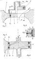
- FIG. 1 The aforementioned substitution principle of a closure part 5 and a seating area 3 of a valve housing 1, 2 with respect to a closing member 4 and its seal 7 can be seen from FIG.
- the closed position of the valve device is shown, with no illustration of the means for actuating the closing member 4 and the closure part 5.
- the seat area 3 interacts with the closing member 4 and its seal 7.
- the open position of the valve device illustratedration on the right
- the effect of the seat area 3 in relation to the seal 7 is substituted by the closure part 5.
- the stress on the seal 7 generated in the closed position of the valve device is caused in other positions than in the closed position by the closure part 5.
- valve device In the open position of the valve device, a throughflow V passes from the valve housing part 1 into the valve housing part 2 or vice versa.
- the closure part 5 has the same dimension D with respect to its bore receiving the closing member 4 as the connecting bore of the valve housing parts 1, 2 in its seating area 3.
- the schematically illustrated valve device is a shut-off valve with an open / close function.
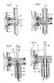
- the closing member 4 was modified from that according to FIG. 1 in such a way that two seals 71, 72 are now provided which accommodate a leakage space 6 between them.
- This leakage space 6 is bordered on the one hand by the valve housing part 1, 2 in the closed position of the valve device, and on the other hand it is connected to the surroundings of the valve device via a drain hole 6a, which is arranged within the closing element 4.
- a drain hole 6a which is arranged within the closing element 4.
- the drain hole 6a can be arranged in a drain pipe 4b, which is connected to the closing member 4 and led out of the valve housing part 2.
- the reversal is also conceivable in that the drain pipe 4b is arranged on the side of the valve housing part 1 and is led out of the latter into the surroundings of the valve.
- FIG. 2 shows the leak-proof valve device in its open position.
- the leakage space 6 is now bordered on the outside by the inner lateral surface of the closure part 5. Both in the closed and in the open position of the valve device, the leakage space 6 is closed off from the interior of the valve housing parts 1 and 2.
- closure part 5 replaces the seating area 3 of the valve housing parts 1 and 2 with respect to the seals 71 and 72 and with respect to the leakage space 6.
- a seat ring (not shown in FIG. 2) can be arranged in the seating area 3, which is equally equipped with the above-mentioned functions on the housing side.
- a so-called “loose” seal 7 is provided in the embodiment according to FIGS. 3 and 4, which is arranged within a groove 4c of the closing element 4.
- the seal 7 has a limited mobility within the groove 4c in the direction of the switching movement of the closing member 4, as a result of which the critical areas between the seal 7 and the groove 4c can be cleaned.
- cleaning of these areas presupposes that the closure part 5 is dimensioned such that there is a spatial connection between the interior of the valve housing parts 1, 2 and the walls surrounding the seal 7.
- FIGS. 5, 6 and 7 show a closing element 4 which, in accordance with the corresponding embodiment of the valve device according to FIG. 2, is equipped with two seals 71 and 72 which enclose a leakage space 6 between them.
- This leakage space 6 is not only connected to the surroundings of the valve device via a drain hole 6a, as shown in FIG. 2, but it also has a second connection path to the surroundings of the valve device, via which cleaning fluid can be introduced into the leakage space 6.
- the aforementioned type of leakage or cleaning agent discharge (denoted by L / R in FIGS. 5 and 6) and the cleaning agent supply R can also be applied to a sealing arrangement according to the embodiment according to FIG. 7, in which the two seals 71 and 72 have limited movement in the closing member 4 are arranged. Solutions in this regard can be found in DE-A-37 01 027 and EP-02 79 177.
- the closing member 4 can be designed as a hollow body between the seals 71 and 72 (FIG. 8), the cleaning liquid being supplied to the area of the seals 71 and 72 via a distribution and spraying device 8.
- the area between the seals 71 and 72 can also be divided by a partition 9 (FIG. 9), which forms a feed area 10 and a discharge area 11, so that the cleaning agent R is forcibly fed to the seal area and also removed from it.
- a partition 9 FIG. 9
- a cleaning pipe 12 with the distributing and spraying device 8 is arranged in the drain hole 6a of the drain pipe 4b.
- the cleaning liquid R is fed to the sealing area and is discharged from there via an annular gap 13, formed between the inner wall of the drain pipe 4b and the cleaning pipe 12.
- the embodiment according to FIG. 11 corresponds essentially to that according to FIG. 9, the inlet for the cleaning liquid R and the outlet for the leakage or cleaning liquid L / R being arranged on one side of the closing element 4.
- the closing member 4 is driven either via the first rod 4a, which is arranged on the side of the closing member 4 opposite the drain pipe 4b, and out of the valve housing part 1 is led out or, if the first rod 4a is dispensed with, via the drain pipe 4b, the installation position of the valve device, as shown in FIG. 11, being present, or an installation position chosen by 180 ° with respect to the arrangement shown.
- valve device according to the invention shown in FIGS. 2 and 5 to 11 are each a so-called leak-free switching double-seat valve. If the closure part 5 is fixedly connected to the valve housing part 1 or 2 via webs, a valve device results with which leakage-limited switching is possible.
- the connecting webs between the closure part 5 and the valve housing part 1 or 2 are to be provided with through openings which correspond approximately to the nominal cross section of the valve. Operation and function of this arrangement are known from the aforementioned patent applications. Here there is an imperative analogy that arises from the various aspects and considerations of the present problem.
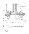
- FIG. 12 shows a valve device according to the invention, which represents the principle of operation of the closure part 5 on which the present invention is based, compared to a seal 7 on the housing, using the simplest switching function, the open / close function.
- the left-hand representation shows the closed position of the valve device, the right-hand side shows its open position.
- the seal 7, which is embedded in a housing groove 1 a with axial play is in a manner known per se by the closing member 4 fixed.
- the housing seal 14 necessary between the valve housing parts 1 and 2 has been shown in a very simplified manner with regard to its arrangement and embedding.
- the closure part 5 can be provided with a multiplicity of openings so that it has the shape of a cage, for example.
- recesses which are continuous from the end face of the closure part 5 and which allow the access of cleaning fluid between the outer lateral surface of the closure part 5 and the seal 7.
- closure member 5 is dimensioned very short in the direction of its switching mobility, so that there is a spatial connection between the interior of the valve housing 1, 2 and the walls surrounding the seal 7, then in the open position of the valve device there is access to cleaning fluid from the Interior of the valve housing 1,2 possible in the sealing area in question.
Landscapes
- Engineering & Computer Science (AREA)
- General Engineering & Computer Science (AREA)
- Mechanical Engineering (AREA)
- Lift Valve (AREA)
- Sliding Valves (AREA)
Abstract
Die Erfindung betrifft ein Verfahren und eine Vorrichtung zum Schutz und zur Stützung einer Dichtung einer Ventilvorrichtung, mit einem schieberartig ausgebildeten, translatorisch oder rotativ verschiebbaren Schließglied, einem hierzu korrespondierenden Sitzbereich der Ventilgehäuseteile und einem Verschlußteil, welches in Richtung des Bewegungsfreiheitsgrades des Schließgliedes verschiebbar ist, und einer Dichtung bzw. Abdichtungsstelle, die entweder zwischen Schließglied und Sitzbereich wirksam ist oder mit dem Verschlußteil zusammen wirkt.The invention relates to a method and a device for protecting and supporting a seal of a valve device, with a slide-like, translationally or rotatably displaceable closing member, a corresponding seat area of the valve housing parts and a closure part, which is displaceable in the direction of the degree of freedom of movement of the closing member, and a seal or sealing point, which is either effective between the closing member and the seat area or cooperates with the closure part.
Durch das vorgeschlagene Verfahren und die Vorrichtung zu seiner Realisierung wird unter anderem sichergestellt, daß bei einer Ventilvorrichtung der einleitend gekennzeichneten Gattung die Dichtung in anderen Stellungen als in der Schließstellung geschützt und gestützt ist.The proposed method and the device for its implementation ensure, among other things, that the seal in a valve device of the genre identified in the introduction is protected and supported in positions other than the closed position.
Dies wird unter anderem verfahrenstechnisch dadurch erreicht, daß die in der Schließstellung der Ventilvorrichtung eine Dichtwirkung erzeugendee Beanspruchung der Dichtung bzw. Abdichtungsstelle in anderen Stellungen als in der Schließstellung durch das Verschlußteil hervorgerufen wird. 
Description
Die Erfindung betrifft ein Verfahren und eine Vorrichtung zum Schutz und zur Stützung einer Dichtung einer Ventilvorrichtung nach dem Oberbegriff des Anspruches 1.The invention relates to a method and a device for protecting and supporting a seal of a valve device according to the preamble of
Eine Ventilvorrichtung der einleitend gekennzeichneten Gattung ist aus der DE-A-37 01 027 und auch aus der europäischen Patentanmeldung 02 79 177 bekannt. Dabei geht der Gegenstand der vorgenannten Patentanmeldungen gemäß dem jeweiligen Oberbegriff des Hauptanspruches von einem Ventil mit Leckageraum aus, welches mit zwei Abdichtungsstellen ausgestattet ist, die seriell angeordnet sind und in der Schließstellung des Ventils das Überströmen von Fluiden von einem Ventilgehäuseteil in ein anderes verhindern. Bei der letztgenannten Patentanmeldung werden die zwei Abdichtungsstellen unter anderem durch eine Dichtungsanordnung mit zwei voneinander getrennten, ventilgehäuseseitig angeordneten Dichtungen realisiert, wobei diese beiden diskreten Dichtungen unter anderem als Dichtungen mit kreisförmigem Querschnitt ausgebildet sind. Der Leckageraum ist bei den beiden bekannten Ventilen zwischen den Abdichtungsstellen angeordnet und über das Ventilgehäuse mit der Umgebung des Ventils verbunden. Mit diesen sogenannten Doppelsitzventilen wird die verfahrenstechnische Aufgabe gelöst, neben der in der Schließstellung des Ventils an sich bekannten Steuerung des Mediumeintritts vom Innenraum des Ventils zum Leckageraum, diesen Eintritt auch in anderen Stellungen des Ventils zu steuern. Die Lösung der verfahrenstechnischen Aufgabe gelingt dadurch, daß der Mediumeintritt vom Innenraum zum Leckageraum in anderen Stellungen als in der Schließstellung des Ventils wirkungsmäßig in gleicher Weise wie in der Schließstellung durch eine das Schließglied hinsichtlich seiner Wechselwirkung mit dem Leckageraum substituierenden Vorkehrung gesteuert wird. Hinsichtlich der gegenständlichen Realisierung ist unter anderem ein Verschlußteil vorgesehen, das einen Innendurchgang aufweist und das zu dem Schließglied relativ beweglich in Richtung dessen Bewegungsfreiheitsgrades angeordnet ist. Dabei hat, zumindest in der Offenstellung des Ventils, das Verschlußteil permanent Kontakt mit den beiden Abdichtungsstellen bzw. den beiden Dichtungen.A valve device of the type identified in the introduction is known from DE-A-37 01 027 and also from European patent application 02 79 177. The subject of the aforementioned patent applications is based on the respective preamble of the main claim of a valve with a leakage space, which is equipped with two sealing points, which are arranged in series and in the closed position of the valve prevent the overflow of fluids from one valve housing part into another. In the last-mentioned patent application, the two sealing points are realized, inter alia, by a seal arrangement with two seals which are separate from one another and arranged on the valve housing side, these two discrete seals being designed, inter alia, as seals with a circular cross section. In the case of the two known valves, the leakage space is arranged between the sealing points and is connected to the surroundings of the valve via the valve housing. With these so-called double-seat valves, the procedural task is solved, in addition to the control of the medium inlet from the interior of the valve to the leakage chamber, which is known per se in the closed position of the valve, of controlling this inlet also in other positions of the valve. The procedural problem is solved in that the medium entry from the interior to the leakage space in others Positions as in the closed position of the valve are operatively controlled in the same way as in the closed position by a provision substituting the closing member with regard to its interaction with the leakage space. With regard to the implementation in question, a closure part is provided, which has an internal passage and which is arranged to be relatively movable in relation to the closing element in the direction of its degree of freedom of movement. Here, at least in the open position of the valve, the closure part is in permanent contact with the two sealing points or the two seals.
Das bekannte Verschlußteil ist stets und in allen Anwendungsfällen im Zusammenwirken mit zwei Dichtungen bzw. Abdichtungsstellen zu sehen und es steuert bestimmungsgemäß allein den Mediumeintritt vom Innenraum zum Leckageraum zwischen den beiden Dichtungen bzw. Abdichtungsstellen.The known closure part is always and in all applications to be seen in cooperation with two seals or sealing points and it controls, as intended, only the medium entry from the interior to the leakage space between the two seals or sealing points.
Bei den bekannten Ventilen übernimmt das Verschlußteil in anderen Stellungen als in der Schließstellung des Ventils den Schutz und die Stützung der beiden Dichtungen bzw. Abdichtungsstellen, falls diese durch ventilgehäuseseitig angeordnete Dichtungsmittel realisiert werden. Für schließgliedseitig angeordnete Dichtungen bietet das bekannte Verschlußteil in seiner vorgeschlagenen Anordnung und Wirkungsweise keinen Schutz und keine Stützung.In the known valves, the closure part takes over the protection and support of the two seals or sealing points in positions other than the closed position of the valve, if these are realized by means of sealing means arranged on the valve housing side. For seals arranged on the closing member side, the known closure part, in its proposed arrangement and mode of operation, offers no protection and no support.
Ausgehend vom aufgezeigten Stand der Technik ist es Aufgabe der vorliegenden Erfindung, bei einer Ventilvorrichtung der einleitend gekennzeichneten Gattung einen Schutz und eine Stützung der Dichtung in anderen Stellungen als in der Schließstellung sicherzustellen. Hierbei sollen hauptsächlich Lösungen aufgezeigt werden, die insbesondere schließgliedseitig angeordnete Dichtungen schützen und stützen.Starting from the prior art shown, it is an object of the present invention to ensure protection and support of the seal in a position other than in the closed position in a valve device of the type identified in the introduction. The main aim is to show solutions that protect and support seals arranged on the closing member side in particular.
Die Aufgabe wird durch die Kennzeichenmerkmale des Anspruchs 1 gelöst. Die Anwendung des erfindungsgemäßen Verfahrens gemäß Unteranspruch 2 auf heute übliche Ventile stattet diese mit Schaltfunktionen und Eigenschaften aus, die neu und vorteilhaft sind.The object is achieved by the characterizing features of
Vorteilhafte Ausführungsformen der Ventilvorrichtung zur Durchführung des vorgenannten Verfahrens sind in den Unteransprüchen 3 bis 8 beschrieben.Advantageous embodiments of the valve device for performing the aforementioned method are described in
Die mit der Erfindung erzielten Vorteile bestehen zum einen insbesondere darin, daß das aus der DE-A-37 01 027 und der EP-02 79 177 bekannte Wirkungsprinzip zwischen Verschlußteil und ventilgehäuseseitig angeordneten Dichtungen konsequent auf Ventile einfachster Bauart mit einer einzigen Auf-/Zu-Funktion einerseits und auf komplexe Ventilvorrichtungen mit den verschiedensten Schaltfunktionen und Eigenschaften andererseits übertragen und angewendet wird. So ist es erstmals möglich, eine Dichtung mit kreisförmigem Querschnitt, einen sogenannten O-Ring, die zwar ein konstruktiv einfaches, insbesondere jedoch bei ventilgehäuseseitiger Anordnung ein nicht unproblematisches Dichtungselement darstellt, begrenzt beweglich in einer gehäuseseitigen Nut anzuordnen, da auch in der Offenstellung des Ventils diese Dichtung durch das Verschlußteil in einer Lage fixiert wird, die ihrer Lage in der Schließstellung des Ventils adäquat ist. Sie wird dadurch auch in der Offenstellung des Ventils der mechanischen Beanspruchung durch das Strömungsmittel entzogen. Bei bekannten Dichtungsanordnungen liegt die gehäuseseitig angeordnete Dichtung in der Offenstellung des Ventils zum Innenraum des Ventilgehäuses hin vollständig offen. Sie ist Strömungskräften, Korrosion und Erosion des Strömungsmittels, zumindest auf ihrer dem Innenraum des Ventilgehäuses zugewandten Oberfläche, ungeschützt unterworfen.The advantages achieved by the invention consist in particular in the fact that the principle of action known from DE-A-37 01 027 and EP-02 79 177 consistently between the closure part and the seals arranged on the valve housing side consistently on valves of the simplest type with a single open / close -Function on the one hand and on complex valve devices with a wide variety of switching functions and properties on the other hand is used and applied. It is now possible for the first time to arrange a seal with a circular cross-section, a so-called O-ring, which is a structurally simple, but in particular a not unproblematic sealing element when arranged on the valve housing side, with limited movement in a housing-side groove, since the valve is also in the open position this seal is fixed by the closure part in a position that is adequate to its position in the closed position of the valve. As a result, it is removed from the mechanical stress caused by the fluid even when the valve is open. In known sealing arrangements, the seal arranged on the housing side is completely open in the open position of the valve towards the interior of the valve housing. It is exposed to flow forces, corrosion and erosion of the fluid, at least on its surface facing the interior of the valve housing, without protection.
Ohne besondere Maßnahmen lassen sich lose Dichtungsanordnungen mit bekannten Mitteln nicht befriedigend lösen. Derartige lose Dichtungsanordnungen sind aber aus biologischen und reinigungstechnischen Gründen beispielsweise in den Vereinigten Staaten von Amerika als Standardlösungen zwingend vorgesehen, wobei dort das Problem durch die Hinnahme der vorstehend beschriebenen mechanischen Instabilität der Dichtung oder durch Armierung der Dichtung oder Anordnung in einem Käfig auf bislang allseits unbefriedigende Weise gelöst wird. Die vorliegende Erfindung löst das bestehende Problem im Zusammenhang mit dem lose angeordneten Dichtungsring mit relativ einfachen Mitteln.Loose sealing arrangements cannot be satisfactorily solved with known means without special measures. Loose sealing arrangements of this type are, however, mandatory for biological and cleaning-related reasons, for example in the United States of America as standard solutions, where the problem there by accepting the mechanical instability of the seal described above or by reinforcing the seal or arranging it in a cage has so far been unsatisfactory Way is solved. The present invention solves the existing problem associated with the loosely arranged sealing ring with relatively simple means.
Die vorgeschlagene Erfindung zeigt aber auch auf, wie das aus den vorgenannten Patentanmeldungen bekannte Wechselwirkungsprinzip zwischen Verschlußteil einerseits und Ventilgehäuse, den beiden Dichtungen bzw. Abdichtungsstellen und dem Leckageraum andererseits nunmehr in Analogie durch ein Wechselwirkungsprinzip zwischen dem Verschlußteil einerseits und dem Schließglied, der Dichtung bzw. den Dichtungen und gegebenenfalls einem Leckageraum andererseits ersetzt wird. Dabei wird zum einen erreicht, daß das Verschlußteil in anderen Stellungen als in der Schließstellung des Ventils eine schließgliedseitig angeordnete Dichtung oder auch deren zwei schützt und stützt. Falls zwischen den beiden schließgliedseitig angeordneten Dichtungen ein Leckageraum angeordnet ist, so wird auch hier der Mediumeintritt vom Innenraum zum Leckageraum in anderen Stellungen als in der Schließstellung des Ventils wirkungsmäßig in gleicher Weise wie in der Schließstellung durch eine das Schließglied hinsichtlich seiner Wechselwirkung mit dem Leckageraum substituierenden Vorkehrung gesteuert.However, the proposed invention also shows how the interaction principle known from the aforementioned patent applications between the closure part on the one hand and the valve housing, the two seals or sealing points and the leakage space on the other hand now analogously by means of an interaction principle between the closure part on the one hand and the closing member, the seal or the seals and possibly a leakage space on the other hand is replaced. It is achieved on the one hand that the closure part in other positions than in the closed position of the valve protects and supports a seal arranged on the closing member side or also two of them. If a leakage space is arranged between the two seals arranged on the closing element side, the medium inlet from the interior to the leakage space is also effective in other positions than in the closed position of the valve in the same way as in the closed position by a substitution of the closing element with regard to its interaction with the leakage space Arrangement controlled.
Die letztgenannte, neugeschaffene Ventilvorrichtung vermag sämtliche bekannten Problemstellungen, wie sie ausführlich in den vorgenannten Patentanmeldungen dargestellt sind, ebenfalls zu lösen. Die verschiedensten Lösungsverfahren und Lösungsmerkmale werden dort genannt. Sie sind sinngemäß und in naheliegender Weise auf die neugeschaffene Ventilvorrichtung übertragbar.The last-mentioned, newly created valve device is also able to solve all known problems, as they are described in detail in the aforementioned patent applications. The most diverse solution processes and solution features are mentioned there. They are analogous and obvious to the newly created valve device.
Da das erfindungsgemäß vorgeschlagene Wechselwirkungsprinzip zwischen Verschlußteil und Schließglied eine Umschlingung des Schließgliedes durch das Verschlußteil in der Offenstellung der Ventilvorrichtung ergibt, entfällt für das Verschlußteil das aus den bekannten Ventilvorrichtungen zu entnehmende Merkmal des zwingend erforderlichen sogenannten "Innendurchgangs". Das Verschlußteil wird nunmehr in der Offenstellung der Ventilvorrichtung nicht mehr vom Strömungsmittel durchströmt. Dadurch ergibt sich ein Vorteil, der darin besteht, daß der Sitzbereich hinsichtlich seines Durchtritts-Querschnittes nicht mehr durch den Ringquerschnitt des Verschlußteils verengt wird. Ein weiterer Vorteil ist darin zu sehen, daß das Verschlußteil auf oder am Schließglied geführt wird, mit dem es in der Offenstellung der Ventilvorrichtung eine Paarung bildet. Bei der bekannten Ventilvorrichtung erfolgt die Führung des Verschlußteils zwar auch am oder auf dem Schließglied, die Paarung wird jedoch mit dem Sitzbereich des Ventilgehäuses vollzogen. Insofern ergeben sich mit der erfindungsgemäßen Vorrichtung geringere Anforderungen an die Führungsqualität bzw. an eine fluchtende Anordnung zwischen Schließgliedachse und Ventilgehäuse.Since the interaction principle proposed according to the invention between the closure part and the closure member results in the closure member being wrapped around the closure part in the open position of the valve device, the feature of the mandatory so-called "inner passage" which is mandatory from the known valve devices is eliminated for the closure part. The closing part is now no longer flowed through by the fluid in the open position of the valve device. This results in an advantage that the seat area is no longer narrowed in terms of its passage cross section by the ring cross section of the closure part. Another advantage is the fact that the closure part is guided on or on the closing member with which it forms a pairing in the open position of the valve device. In the known valve device, the closing part is also guided on or on the closing member, but the pairing is carried out with the seat area of the valve housing. In this respect, the device according to the invention results in lower demands on the guiding quality or on an aligned arrangement between the closing member axis and the valve housing.
Zwei schließgliedseitig angeordnete Dichtungen, zwischen denen ein Leckageraum angeordnet ist, der über Leitungen mit der Umgebung der Ventilvorrichtung verbunden ist, lassen sich mit den aus den vorgenannten Patentanmeldungen bekannten Mitteln sowohl in der Schließ- als auch in der Offenstellung der Ventilvorrichtung reinigen. Die Reinigung einer einzigen Dichtung, die entweder ventilgehäuseseitig oder schließgliedseitig angeordnet ist und die erfindungsgemäß in allen Stellungen des Ventils gegenüber dem Innenraum des Ventilgehäuses abgedeckt ist, ist nach einer vorteilhaften Ausführungsform der Ventilvorrichtung gemäß der Erfindung dadurch gegeben, daß das Verschlußteil im Bereich seiner Überdeckung mit der Dichtung vom Innenraum des Ventilgehäuses zur Dichtung hin durchlässig ausgebildet ist. Da das Verschlußteil in diesem Falle keine Abdichtungsfunktion zu übernehmen hat, sondern lediglich die Dichtung in ihrer gehäuseseitigen Lage in der Offenstellung des Ventils schützen und stützen soll, kann es beispielsweise mit einer Vielzahl von Durchbrüchen versehen sein.Two seals arranged on the closing element side, between which a leakage space is arranged, which is connected via lines to the surroundings of the valve device, can be cleaned with the means known from the aforementioned patent applications, both in the closed and in the open position of the valve device. The cleaning of a single seal, which is arranged either on the valve housing side or on the closing member side and which is covered according to the invention in all positions of the valve with respect to the interior of the valve housing, is provided according to an advantageous embodiment of the valve device according to the invention in that the closure part in the area of its overlap the seal is designed to be permeable from the interior of the valve housing to the seal. Since the closure part has no sealing function in this case, but is only intended to protect and support the seal in its position on the housing in the open position of the valve, it can be provided, for example, with a large number of openings.
Durch eine weitere Ausgestaltung der Ventilvorrichtung gemäß der Erfindung erreicht man die Reinigungsfähigkeit der einzigen Dichtung vom Innenraum des Ventilgehäuseteils aus dadurch, daß das Verschlußteil in Richtung seiner Schaltbeweglichkeit derart bemessen ist, daß eine räumliche Verbindung zwischen dem Innenraum des Ventilgehäuses und den die Dichtung umgebenden Wandungen gegeben ist. Diese reinigungstechnisch bedingte Bemessungsnotwendigkeit führt zu einem sehr flach ausgebildeten Verschlußteil.A further embodiment of the valve device according to the invention achieves the cleanability of the single seal from the interior of the valve housing part in that the closure part is dimensioned in the direction of its shifting mobility in such a way that there is a spatial connection between the interior of the valve housing and the walls surrounding the seal is. This dimensioning necessity, which is caused by cleaning technology, leads to a very flat closure part.
Anhand der nachfolgend kurz erläuterten Figuren der Zeichnung wird der Anmeldungsgegenstand in seinen wesentlichen Merkmalen beispielhaft dargestellt und hinsichtlich seiner Wirkungsweise beschrieben. Es werden folgende Kennzeichen und Bezeichnungen verwendet (s. Liste):On the basis of the figures of the drawing briefly explained below, the essential features of the subject of the application are shown by way of example and their mode of operation is described. The following labels and designations are used (see list):
Es zeigen:
-
Figur 1 in vereinfachter schematischer Darstellung einen Mittelschnitt durch eine Ventilvorrichtung gemäß der Erfindung mit einer im Schließglied angeordneten Dichtung in der Schließ- und in der Offenstellung (linksseitige bzw. rechtsseitige Darstellung); -
Figur 2 einen Mittelschnitt durch eine andere Ausführungsform der Ventilvorrichtung gemäß der Erfindung mit zwei schließgliedseitig angeordneten Dichtungen und einem dazwischen angeordneten Leckageraum, ebenfalls in der Schließ- und der Offenstellung; -
Figur 3 undFigur 4 einen Mittelschnitt durch eine Ausführungsform gemäßFigur 1 mit einer begrenzt beweglich angeordneten Dichtung in der Schließ- und in der Offenstellung; -
Figur 5 undFigur 6 einen Mittelschnitt durch eine Ausführungsform gemäßFigur 2 mit einem Reinigungsmittelzulauf zum Leckageraum in der Schließ- und in der Offenstellung des Ventils; -
Figur 7 eine Ausführungsform gemäßFiguren 5 und 6 mit einem abgewandelten Reinigungsmittelzulauf und -ablauf; -
Figuren 8 bis 11 jeweils einen Mittelschnitt durch eine Ventilvorrichtung gemäß denFiguren 5 und 6 mit begrenzt beweglichen Dichtungen und unterschiedlich ausgestaltetem Zulauf für das Reinigungsmittel und Ablauf für das Reinigungsmittel bzw. die Leckage; - Figur 12 einen Mittelschnitt durch eine andere Ausführungsform der Ventilvorrichtung gemäß der Erfindung mit einer ventilgehäuseseitig angeordneten Dichtung in der Schließ- und der Offenstellung (linksseitige bzw. rechtsseitige Darstellung).
- 1 shows a simplified schematic illustration of a central section through a valve device according to the invention with a seal arranged in the closing element in the closed and in the open position (left-hand and right-hand view);
- FIG. 2 shows a central section through another embodiment of the valve device according to the invention with two seals arranged on the closing element side and a leakage space arranged between them, likewise in the closed and open positions;
- FIG. 3 and FIG. 4 a middle section through an embodiment according to FIG. 1 with a seal which is arranged to be movable to a limited extent in the closed and in the open position;
- FIG. 5 and FIG. 6 a middle section through an embodiment according to FIG. 2 with a cleaning agent inlet to the leakage space in the closed and in the open position of the valve;
- 7 shows an embodiment according to FIGS. 5 and 6 with a modified cleaning agent inlet and outlet;
- FIGS. 8 to 11 each show a central section through a valve device according to FIGS. 5 and 6 with seals which can be moved to a limited extent and a differently designed inlet for the cleaning agent and outlet for the cleaning agent or the leak;
- FIG. 12 shows a central section through another embodiment of the valve device according to the invention with a seal arranged on the valve housing side in the closed and open positions (left-hand and right-hand representation).
Aus Figur 1 ist das vorgenannte Substitutionsprinzip von einem Verschlußteil 5 und einem Sitzbereich 3 eines Ventilgehäuses 1,2 gegenüber einem Schließglied 4 und dessen Dichtung 7 erkennbar. In der linksseitigen Darstellung ist die Schließstellung der Ventilvorrichtung gezeigt, wobei auf eine Darstellung der Mittel zur Betätigung des Schließgliedes 4 und des Verschlußteiles 5 verzichtet wurde. Der Sitzbereich 3 steht in Wechselwirkung mit dem Schließglied 4 und seiner Dichtung 7. In der Offenstellung der Ventilvorrichtung (rechtsseitige Darstellung) wird die Wirkung des Sitzbereiches 3 in Bezug auf die Dichtung 7 durch das Verschlußteil 5 substituiert. Die in der Schließstellung der Ventilvorrichtung eine Dichtwirkung erzeugte Beanspruchung der Dichtung 7 wird in anderen Stellungen als in der Schließstellung durch das Verschlußteil 5 hervorgerufen. In der Offenstellung der Ventilvorrichtung gelangt eine Durchtrittsströmung V vom Ventilgehäuseteil 1 in das Ventilgehäuseteil 2 oder umgekehrt. Das Verschlußteil 5 weist hinsichtlich seiner das Schließglied 4 aufnehmenden Bohrung die gleiche Abmessung D auf, wie die Verbindungsbohrung der Ventilgehäuseteile 1,2 in ihrem Sitzbereich 3. Bei der schematisch dargestellten Ventilvorrichtung handelt es sich um ein Absperrventil mit Auf/Zu-Funktion.The aforementioned substitution principle of a
Das Schließglied 4 wurde bei der Ausführungsform gemäß Figur 2 gegenüber jener gemäß Figur 1 dahingehend abgewandelt, daß nunmehr zwei Dichtungen 71, 72 vorgesehen sind, die einen Leckageraum 6 zwischen sich aufnehmen.In the embodiment according to FIG. 2, the closing
Dieser Leckageraum 6 wird in der Schließstellung der Ventilvorrichtung einerseits von dem Ventilgehäuseteil 1,2 berandet, und er ist andererseits über eine Ablaufbohrung 6a, die innerhalb des Schließgliedes 4 angeordnet ist, mit der Umgebung der Ventilvorrichtung verbunden. Für die Anordnung der Ablaufbohrung 6a innerhalb des Schließgliedes 4 sind eine Reihe von Lösungen bekannt, z. B. kann die Ablaufbohrung 6a in einem Ablaufrohr 4b, das mit dem Schließglied 4 verbunden und aus dem Ventilgehäuseteil 2 herausgeführt ist, angeordnet werden. Ebenso ist die Umkehrung denkbar, indem das Ablaufrohr 4b auf der Seite des Ventilgehäuseteils 1 angeordnet und aus diesem in die Umgebung des Ventils herausgeführt ist. Im letztgenannten Fall befindet sich die Ablaufbohrung 6a dann in einer ersten Stange 4a, mit der das Schließglied 4 betätigt wird. Weitere Ausgestaltungen der Ventilvorrichtung hinsichtlich der Anordnung der Ablaufbohrung 6a ergeben sich auch aus den Figuren 8, 9, 10 und 11 (Ablaufbohrung 6a in einem nach unten herausgeführten Ablaufrohr 4b). Die rechtsseitige Darstellung der Figur 2 zeigt die leckagegesicherte Ventilvorrichtung in ihrer Offenstellung. Der Leckageraum 6 wird nunmehr außenseits von der inneren Mantelfläche des Verschlußteils 5 berandet. Sowohl in der Schließ- als auch in der Offenstellung der Ventilvorrichtung ist der Leckageraum 6 gegenüber dem Innenraum der Ventilgehäuseteile 1 bzw. 2 abgeschlossen. Man erkennt weiterhin, daß das Verschlußteil 5 in Bezug auf die Dichtungen 71 und 72 und in Bezug auf den Leckageraum 6 den Sitzbereich 3 der Ventilgehäuseteile 1 und 2 substituiert. Im Sitzbereich 3 kann ein in Figur 2 nicht dargestellter Sitzring angeordnet werden, der mit den vorstehend genannten gehäuseseitigen Funktionen gleichermaßen ausgestattet ist.This
Im Gegensatz zur Ausführungsform gemäß Figur 1 ist bei der Ausführungsform gemäß den Figuren 3 und 4 eine sogenannte "lose" Dichtung 7 vorgesehen, die innerhalb einer Nut 4c des Schließgliedes 4 angeordnet ist. Die Dichtung 7 besitzt innerhalb der Nut 4c in Richtung der Schaltbewegung des Schließgliedes 4 eine begrenzte Beweglichkeit, wodurch die Reinigungsfähigkeit der kritischen Bereiche zwischen Dichtung 7 und Nut 4c erreicht wird. Eine Reinigung dieser Bereiche setzt allerdings voraus, daß das Verschlußteil 5 derart bemessen ist, daß eine räumliche Verbindung zwischen dem Innenraum der Ventilgehäuseteile 1,2 und den die Dichtung 7 umgebenden Wandungen gegeben ist. Mit 4a und 5a sind die erste Stange bzw. die zweite Stange zur Betätigung des Schließgliedes 4 bzw. des Verschlußteils 5 gekennzeichnet.In contrast to the embodiment according to FIG. 1, a so-called “loose”
In den Figur 5, 6 und 7 ist ein Schließglied 4 dargestellt, welches in Übereinstimmung mit der entsprechenden Ausführungsform der Ventilvorrichtung gemäß Figur 2 mit zwei Dichtungen 71 und 72 ausgestattet ist, die zwischen sich einen Leckageraum 6 einschließen. Dieser Leckageraum 6 ist nicht nur, wie in Figur 2 dargestellt, über eine Ablaufbohrung 6a mit der Umgebung der Ventilvorrichtung verbunden, sondern er weist darüber hinaus einen zweiten Verbindungsweg zur Umgebung der Ventilvorrichtung auf, über den Reinigungsflüssigkeit in den Leckageraum 6 eingebracht werden kann. Die vorgenannte Art der Leckage- bzw. Reinigungsmittelabführung (in den Figuren 5 und 6 mit L/R bezeichnet) und die Reinigungsmittelzuführung R sind auch auf eine Dichtungsanordnung gemäß Ausführungsform nach Figur 7 anwendbar, in der die beiden Dichtungen 71 und 72 begrenzt beweglich im Schließglied 4 angeordnet sind. Diesbezügliche Lösungen sind der DE-A-37 01 027 und der EP-02 79 177 zu entnehmen. Darüber hinaus zeigen die Figuren 8, 9, 10 und 11 Lösungen auf, wie das Reinigungsmittel in den Leckageraum 6 eingeleitet bzw. diesem zugeführt wird.FIGS. 5, 6 and 7 show a
Beispielsweise kann das Schließglied 4 als Hohlkörper zwischen den Dichtungen 71 und 72 ausgebildet sein (Figur 8), wobei die Reinigungsflüssigkeit über einer Verteil- und Spritzeinrichtung 8 dem Bereich der Dichtungen 71 und 72 zugeführt wird.For example, the closing
Der Bereich zwischen den Dichtungen 71 und 72 kann auch durch eine Trennwand 9 geteilt sein (Figur 9), die einen Zuführungsbereich 10 und einen Abführungsbereich 11 bildet, so daß das Reinigungsmittel R dem Dichtungsbereich zwangsweise zugeführt und ebenso aus diesem wieder abgeführt wird.The area between the
Bei der Ausführungsform gemäß Figur 10 ist ein Reinigungsrohr 12 mit der Verteil- und Spritzeinrichtung 8 in der Ablaufbohrung 6a des Ablaufrohres 4b angeordnet. Die Reinigungsflüssigkeit R wird dem Dichtungsbereich zugeführt und von dort über einen Ringspalt 13, gebildet zwischen der Innenwandung des Ablaufrohres 4b und dem Reinigungsrohr 12, abgeführt.In the embodiment according to FIG. 10, a cleaning pipe 12 with the distributing and spraying
Die Ausführungsform gemäß Figur 11 entspricht in ihrem wesentlichen Aufbau jener gemäß Figur 9, wobei der Zulauf für die Reinigungsflüssigkeit R und der Ablauf für die Leckage- bzw. Reinigungsflüssigkeit L/R auf einer Seite des Schließgliedes 4 angeordnet sind. Der Antrieb des Schließgliedes 4 erfolgt entweder über die erste Stange 4a, die auf der dem Ablaufrohr 4b gegenüberliegenden Seite des Schließgliedes 4 angeordnet und aus dem Ventilgehäuseteil 1 herausgeführt ist oder, bei Verzicht auf die erste Stange 4a, über das Ablaufrohr 4b, wobei die Einbaulage der Ventilvorrichtung, wie in Figur 11 dargestellt, vorliegt oder aber eine um 180° gegenüber der dargestellten Anordnung gewählte Einbaulage.The embodiment according to FIG. 11 corresponds essentially to that according to FIG. 9, the inlet for the cleaning liquid R and the outlet for the leakage or cleaning liquid L / R being arranged on one side of the
Bei dem in den Figuren 2 und 5 bis 11 dargestellten Ausführungsformen der Ventilvorrichtung gemäß der Erfindung handelt es sich um jeweils ein sogenanntes leckagefrei schaltendes Doppelsitzventil. Falls das Verschlußteil 5 über Stege fest mit dem Ventilgehäuseteil 1 bzw. 2 verbunden ist, so ergibt sich eine Ventilvorrichtung, mit der ein leckagebegrenztes Schalten möglich ist. Die Verbindungsstege zwischen dem Verschlußteil 5 und dem Ventilgehäuseteil 1 bzw. 2 sind dabei mit Durchtrittsöffnungen, die näherungsweise dem Nennquerschnitt des Ventils entsprechen, zu versehen. Wirkungsweise und Funktion dieser Anordnung sind aus den vorgenannten Patentanmeldungen bekannt. Hier besteht eine sich unter den vielfältigen Aspekten und Betrachtungsweisen des vorliegenden Problems ergebende zwingende Analogie.The embodiments of the valve device according to the invention shown in FIGS. 2 and 5 to 11 are each a so-called leak-free switching double-seat valve. If the
In Figur 12 ist eine Ventilvorrichtung gemäß der Erfindung dargestellt, die das der vorliegenden Erfindung zugrundeliegende Wirkungsprinzip des Verschlußteils 5 gegenüber einer gehäuseseitigen Dichtung 7 anhand der einfachsten Schaltfunktion, der Auf/Zu-Funktion, darstellt. Die linksseitige Darstellung zeigt die Schließstellung der Ventilvorrichtung, die rechtsseitige ihre Offenstellung. In der Schließstellung der Ventilvorrichtung wird die Dichtung 7, die mit axialem Spiel in einer Gehäusenut 1a eingebettet ist, in an sich bekannter Weise durch das Schließglied 4 fixiert. Der Einfachheit halber wurde die zwischen den Ventilgehäuseteilen 1 und 2 notwendige Gehäusedichtung 14 hinsichtlich ihrer Anordnung und Einbettung stark vereinfacht dargestellt. Das Wesen der Erfindung ergibt sich aus der Offenstellung der Ventilvorrichtung (rechtsseitige Darstellung), in der das Verschlußteil 5 die in der Schließstellung vom Schließglied 4 eingenommene Lage gegenüber der Dichtung 7 substituiert hat. In keiner der gezeigten Schaltzustände, auch nicht in den nicht dargestellten Zwischenzuständen, ist die sogenannte "lose" Dichtung 7 dem mechanischen Angriff des Strömungsmittels ausgesetzt.FIG. 12 shows a valve device according to the invention, which represents the principle of operation of the
Die Dichtung 7 und die sie umgebende Gehäusenut 1a wird in der Offenstellung der Ventilvorrichtung für Reinigungsflüssigkeit zugängig, wenn das Verschlußteil 5 im Bereich seiner Überdeckung mit der Dichtung 7 vom Innenraum des Ventilgehäuses 1,2 zur Dichtung 7 hin durchlässig ausgebildet ist. Beispielweise kann das Verschlußteil 5 mit einer Vielzahl von Öffnungen versehen sein, so daß es zum Beispiel die Form eines Käfigs besitzt. Es können aber auch von der Stirnseite des Verschlußteils 5 durchgehende Ausnehmungen vorgesehen werden, die den Zutritt von Reinigungsflüssigkeit zwischen der äußeren Mantelfläche des Verschlußteils 5 und der Dichtung 7 ermöglichen.The
Wenn das Verschlußteil 5 in Richtung seiner, Schaltbeweglichkeit sehr kurz bemessen wird, so daß eine räumliche Verbindung zwischen dem Innenraum des Ventilgehäuses 1,2 und den die Dichtung 7 umgebenden Wandungen gegeben ist, dann ist in der Offenstellung der Ventilvorrichtung der Zutritt von Reinigungsflüssigkeit aus dem Innenraum des Ventilgehäuses 1,2 in den in Frage kommenden Dichtungsbereich möglich.If the
- 1,2 Ventilgehäuseteil1.2 valve housing part
- 1a Gehäusenut1a housing groove
- 3 Sitzbereich3 seating area
- 4 Schließglied4 closing link
- 4a erste Stange4a first rod
- 4b Ablaufrohr4b drain pipe
- 4c Nut4c groove
- 5 Verschlußteil5 closure part
- 5a zweite Stange5a second rod
- 6 Leckageraum6 leakage room
- 6a Ablaufbohrung6a drain hole
- 7 Dichtung7 seal
- 71 erste Dichtung71 first seal
- 72 zweite Dichtung72 second seal
- 8 Verteil- und Spritzeinrichtung8 Distribution and spraying device
- 9 Trennwand9 partition
- 10 Zuführungsbereich10 feed area
- 11 Abführungsbereich11 discharge area
- 12 Reinigungsrohr12 cleaning pipe
- 13 Ringspalt13 annular gap
- 14 Gehäusedichtung14 Housing seal
- D Durchmesser des SitzbereichesD diameter of the seating area
- L Leckageabfuhr/LeckageL Leakage removal / leakage
- R Reinigungsmittelzufuhr bzw. -abfuhr/ReinigungsmittelR Supply or removal of cleaning agents / cleaning agents
- V DurchtrittsströmungV passage flow
Claims (8)
Applications Claiming Priority (4)
| Application Number | Priority Date | Filing Date | Title |
|---|---|---|---|
| DE3801569 | 1988-01-20 | ||
| DE19883801569 DE3801569A1 (en) | 1988-01-20 | 1988-01-20 | Method and device for the construction of a valve seat with a seal arranged on the housing side |
| DE19883801561 DE3801561A1 (en) | 1988-01-20 | 1988-01-20 | Valve device |
| DE3801561 | 1988-01-20 |
Publications (2)
| Publication Number | Publication Date |
|---|---|
| EP0337519A2 true EP0337519A2 (en) | 1989-10-18 |
| EP0337519A3 EP0337519A3 (en) | 1991-09-18 |
Family
ID=25864106
Family Applications (2)
| Application Number | Title | Priority Date | Filing Date |
|---|---|---|---|
| EP19890200512 Pending EP0337519A3 (en) | 1988-01-20 | 1989-01-17 | Method and device for the protection and the support of a valve gasket |
| EP19890902506 Expired - Lifetime EP0356491B1 (en) | 1988-01-20 | 1989-01-17 | Valve arrangement |
Family Applications After (1)
| Application Number | Title | Priority Date | Filing Date |
|---|---|---|---|
| EP19890902506 Expired - Lifetime EP0356491B1 (en) | 1988-01-20 | 1989-01-17 | Valve arrangement |
Country Status (10)
| Country | Link |
|---|---|
| US (1) | US5048555A (en) |
| EP (2) | EP0337519A3 (en) |
| JP (1) | JPH02501848A (en) |
| KR (1) | KR900700808A (en) |
| BR (1) | BR8904794A (en) |
| DE (1) | DE58904609D1 (en) |
| DK (1) | DK460989D0 (en) |
| FI (1) | FI894438A0 (en) |
| RU (1) | RU1839701C (en) |
| WO (1) | WO1989006763A1 (en) |
Cited By (2)
| Publication number | Priority date | Publication date | Assignee | Title |
|---|---|---|---|---|
| FR2676265A1 (en) * | 1991-05-06 | 1992-11-13 | Dana Corp | VALVE SYSTEM FOR CONTROLLING FLOW OF WATER TO A TURBINE ENGINE. |
| GB2277792A (en) * | 1993-05-05 | 1994-11-09 | Kent Introl Ltd | Flow control valve |
Families Citing this family (9)
| Publication number | Priority date | Publication date | Assignee | Title |
|---|---|---|---|---|
| US5520209A (en) * | 1993-12-03 | 1996-05-28 | The Dow Chemical Company | Fluid relief device |
| US5836395A (en) * | 1994-08-01 | 1998-11-17 | Weatherford/Lamb, Inc. | Valve for wellbore use |
| DE19842922A1 (en) * | 1998-09-18 | 2000-03-23 | Rieger Gmbh & Co Kg Geb | Valve, especially double seat valve |
| FR2795803B1 (en) * | 1999-06-30 | 2001-08-17 | Legris Sa | QUICK CONNECTION DEVICE WITH PROTECTED JOINT OF A TUBE TO A RIGID ELEMENT |
| DE102004024215A1 (en) * | 2004-05-15 | 2005-12-08 | L'orange Gmbh | control valve |
| DE102004040678B3 (en) * | 2004-08-20 | 2006-02-02 | Müller, Rita | Valve for thermo-regenerative cleaning of exhaust fumes, comprising upper and lower locking plate |
| DE102005051467A1 (en) * | 2005-10-24 | 2007-04-26 | Südmo Holding GmbH | Manifold arrangement |
| US8327881B2 (en) * | 2008-09-19 | 2012-12-11 | Spx Corporation | Double seat valve apparatus |
| US9328837B2 (en) * | 2012-10-04 | 2016-05-03 | Spx Flow, Inc. | Double seat valve with isolated vent chambers |
Family Cites Families (13)
| Publication number | Priority date | Publication date | Assignee | Title |
|---|---|---|---|---|
| BE447878A (en) * | ||||
| GB195692A (en) * | 1921-12-06 | 1923-04-06 | Edward Albert Mitchell | Improvements in stop valves |
| US2469921A (en) * | 1945-03-07 | 1949-05-10 | Glenn L Martin Co | Valve |
| US2583539A (en) * | 1946-06-05 | 1952-01-29 | Bashark Nicholas | Valve packing construction |
| GB668563A (en) * | 1948-05-15 | 1952-03-19 | Marvin H Grove | Valve construction |
| FR1204043A (en) * | 1957-10-03 | 1960-01-22 | Bryan Donkin Co Ltd | Sealing ring valve |
| CH519131A (en) * | 1970-07-24 | 1972-02-15 | Bbc Brown Boveri & Cie | Gas valve designed as a hollow slide |
| US3776260A (en) * | 1971-04-13 | 1973-12-04 | Burnett & Rolfe Ltd | Beer kegs and like containers |
| SE424357B (en) * | 1979-11-20 | 1982-07-12 | Hakan Jeppsson | VALVE WITH DOUBLE SEALS |
| SE432982B (en) * | 1980-04-24 | 1984-04-30 | Alfa Laval Ab | MIXING SAFETY VALVE |
| US4605035A (en) * | 1984-09-14 | 1986-08-12 | Lavrids Knudsen Maskinefabrik A/S | Double seat valve |
| DE3502919A1 (en) * | 1985-01-29 | 1986-07-31 | Bayerische Motoren Werke AG, 8000 München | INJECTION VALVE FOR MIX-COMPRESSIVE INTERNAL COMBUSTION ENGINES |
| DE3701027A1 (en) * | 1987-01-16 | 1988-07-28 | Hans Otto Mieth | METHOD AND DEVICE FOR CONTROLLING A LEAKAGE SPACE OF A VALVE |
-
1988
- 1988-09-19 RU SU884742122A patent/RU1839701C/en active
-
1989
- 1989-01-17 US US07/415,343 patent/US5048555A/en not_active Expired - Fee Related
- 1989-01-17 BR BR8904794A patent/BR8904794A/en unknown
- 1989-01-17 EP EP19890200512 patent/EP0337519A3/en active Pending
- 1989-01-17 WO PCT/EP1989/000044 patent/WO1989006763A1/en not_active Ceased
- 1989-01-17 JP JP1502325A patent/JPH02501848A/en active Pending
- 1989-01-17 KR KR1019890701716A patent/KR900700808A/en not_active Ceased
- 1989-01-17 DE DE8989902506T patent/DE58904609D1/en not_active Expired - Fee Related
- 1989-01-17 EP EP19890902506 patent/EP0356491B1/en not_active Expired - Lifetime
- 1989-09-19 FI FI894438A patent/FI894438A0/en not_active Application Discontinuation
- 1989-09-19 DK DK460989A patent/DK460989D0/en not_active Application Discontinuation
Cited By (3)
| Publication number | Priority date | Publication date | Assignee | Title |
|---|---|---|---|---|
| FR2676265A1 (en) * | 1991-05-06 | 1992-11-13 | Dana Corp | VALVE SYSTEM FOR CONTROLLING FLOW OF WATER TO A TURBINE ENGINE. |
| GB2277792A (en) * | 1993-05-05 | 1994-11-09 | Kent Introl Ltd | Flow control valve |
| GB2277792B (en) * | 1993-05-05 | 1997-08-06 | Kent Introl Ltd | Valve |
Also Published As
| Publication number | Publication date |
|---|---|
| WO1989006763A1 (en) | 1989-07-27 |
| DK460989A (en) | 1989-09-19 |
| EP0356491B1 (en) | 1993-06-09 |
| JPH02501848A (en) | 1990-06-21 |
| DE58904609D1 (en) | 1993-07-15 |
| RU1839701C (en) | 1993-12-30 |
| DK460989D0 (en) | 1989-09-19 |
| FI894438A7 (en) | 1989-09-19 |
| KR900700808A (en) | 1990-08-17 |
| BR8904794A (en) | 1990-05-08 |
| US5048555A (en) | 1991-09-17 |
| FI894438A0 (en) | 1989-09-19 |
| EP0337519A3 (en) | 1991-09-18 |
| EP0356491A1 (en) | 1990-03-07 |
Similar Documents
| Publication | Publication Date | Title |
|---|---|---|
| EP0279177B1 (en) | Valve with a controlled leakage space | |
| EP0968382B1 (en) | Double seat valve with cleanable seats | |
| DE4118874A1 (en) | METHOD FOR CLEANING A LEAK-FREE SWITCHING DOUBLE SEAT VALVE AND VALVE DEVICE FOR CARRYING OUT THE METHOD | |
| EP0625250B1 (en) | Double seat valve | |
| EP0122323A1 (en) | Double-seat valve with two valve heads | |
| EP0337519A2 (en) | Method and device for the protection and the support of a valve gasket | |
| DE19608792C2 (en) | Seat-cleanable double seat valve | |
| DE3835363C2 (en) | Method and device for controlling the medium entry into at least one leakage space of a valve device | |
| DE3048219C2 (en) | ||
| WO1995008730A1 (en) | Leak-free switching process for a double seat valve and sealing arrangement for carrying out the process | |
| EP3852900B1 (en) | Device for filtering a fluid, in particular bernoulli filtering device | |
| DE19842603C2 (en) | Seat-cleanable double seat valve | |
| DE4224001C1 (en) | Valve for backwashing milking cups in milking systems | |
| DE4203723C2 (en) | Double seat valve | |
| EP0046162B1 (en) | Single-lever mixing valve for the modulating of a water-beam | |
| DE3801561A1 (en) | Valve device | |
| EP1581757B1 (en) | Double-seat valve | |
| EP0928915A2 (en) | Double-seat valve with leak control | |
| EP0983442B1 (en) | Manually operated emergency control actuation device | |
| DE3801569A1 (en) | Method and device for the construction of a valve seat with a seal arranged on the housing side | |
| DE29714924U1 (en) | Double seat valve with a controlled leakage outlet | |
| DE3736644A1 (en) | Sealing device for a valve stem displaceable in its axial direction | |
| EP0891506A1 (en) | Double-seated valve with a controlled leakage space | |
| DE9313613U1 (en) | Double seat valve |
Legal Events
| Date | Code | Title | Description |
|---|---|---|---|
| PUAI | Public reference made under article 153(3) epc to a published international application that has entered the european phase |
Free format text: ORIGINAL CODE: 0009012 |
|
| AK | Designated contracting states |
Kind code of ref document: A2 Designated state(s): ES |
|
| STAA | Information on the status of an ep patent application or granted ep patent |
Free format text: STATUS: REQUEST FOR EXAMINATION WAS MADE |
|
| 17P | Request for examination filed |
Effective date: 19891110 |
|
| PUAL | Search report despatched |
Free format text: ORIGINAL CODE: 0009013 |
|
| AK | Designated contracting states |
Kind code of ref document: A3 Designated state(s): ES |
|
| XX | Miscellaneous (additional remarks) |
Free format text: VERFAHREN ABGESCHLOSSEN INFOLGE VERBINDUNG MIT 89902506.8/0356491 (EUROPAEISCHE ANMELDENUMMER/VEROEFFENTLICHUNGSNUMMER) VOM 11.03.92. |