EP0337016B1 - Fachwerkartige Stromschienen-Anordnung für Beleuchtungszwecke - Google Patents
Fachwerkartige Stromschienen-Anordnung für Beleuchtungszwecke Download PDFInfo
- Publication number
- EP0337016B1 EP0337016B1 EP88121475A EP88121475A EP0337016B1 EP 0337016 B1 EP0337016 B1 EP 0337016B1 EP 88121475 A EP88121475 A EP 88121475A EP 88121475 A EP88121475 A EP 88121475A EP 0337016 B1 EP0337016 B1 EP 0337016B1
- Authority
- EP
- European Patent Office
- Prior art keywords
- frame
- arrangement according
- busbar arrangement
- securing
- hollow section
- Prior art date
- Legal status (The legal status is an assumption and is not a legal conclusion. Google has not performed a legal analysis and makes no representation as to the accuracy of the status listed.)
- Expired - Lifetime
Links
- 239000002184 metal Substances 0.000 claims description 7
- 229910052751 metal Inorganic materials 0.000 claims description 7
- 241000122469 Hypericum hypericoides Species 0.000 claims description 3
- 230000008878 coupling Effects 0.000 claims description 3
- 238000010168 coupling process Methods 0.000 claims description 3
- 238000005859 coupling reaction Methods 0.000 claims description 3
- 238000004512 die casting Methods 0.000 claims description 3
- 238000005266 casting Methods 0.000 claims 1
- 229910000831 Steel Inorganic materials 0.000 description 7
- 239000004020 conductor Substances 0.000 description 7
- 239000010959 steel Substances 0.000 description 7
- 239000011230 binding agent Substances 0.000 description 4
- 210000003128 head Anatomy 0.000 description 4
- 239000000945 filler Substances 0.000 description 3
- 239000011810 insulating material Substances 0.000 description 3
- RYGMFSIKBFXOCR-UHFFFAOYSA-N Copper Chemical compound [Cu] RYGMFSIKBFXOCR-UHFFFAOYSA-N 0.000 description 2
- 229910052802 copper Inorganic materials 0.000 description 2
- 239000010949 copper Substances 0.000 description 2
- 238000000926 separation method Methods 0.000 description 2
- 125000006850 spacer group Chemical group 0.000 description 2
- 238000010521 absorption reaction Methods 0.000 description 1
- 239000000969 carrier Substances 0.000 description 1
- 230000000295 complement effect Effects 0.000 description 1
- 230000006835 compression Effects 0.000 description 1
- 238000007906 compression Methods 0.000 description 1
- 230000002349 favourable effect Effects 0.000 description 1
- 238000009434 installation Methods 0.000 description 1
- 239000000463 material Substances 0.000 description 1
- 230000003287 optical effect Effects 0.000 description 1
- 230000000149 penetrating effect Effects 0.000 description 1
- 230000035515 penetration Effects 0.000 description 1
- 230000001105 regulatory effect Effects 0.000 description 1
Images




Classifications
-
- F—MECHANICAL ENGINEERING; LIGHTING; HEATING; WEAPONS; BLASTING
- F21—LIGHTING
- F21S—NON-PORTABLE LIGHTING DEVICES; SYSTEMS THEREOF; VEHICLE LIGHTING DEVICES SPECIALLY ADAPTED FOR VEHICLE EXTERIORS
- F21S2/00—Systems of lighting devices, not provided for in main groups F21S4/00 - F21S10/00 or F21S19/00, e.g. of modular construction
-
- F—MECHANICAL ENGINEERING; LIGHTING; HEATING; WEAPONS; BLASTING
- F21—LIGHTING
- F21V—FUNCTIONAL FEATURES OR DETAILS OF LIGHTING DEVICES OR SYSTEMS THEREOF; STRUCTURAL COMBINATIONS OF LIGHTING DEVICES WITH OTHER ARTICLES, NOT OTHERWISE PROVIDED FOR
- F21V21/00—Supporting, suspending, or attaching arrangements for lighting devices; Hand grips
- F21V21/34—Supporting elements displaceable along a guiding element
- F21V21/35—Supporting elements displaceable along a guiding element with direct electrical contact between the supporting element and electric conductors running along the guiding element
Definitions
- the invention relates to a truss-like busbar arrangement, as has become known from DE-A-29 15 502.
- two busbars are held together in an upright arrangement on the foot and head side by means of special foot and head connectors.
- Two such double-track busbars are fastened to one another via two equally long, horizontally extending binders composed of two half-shells. This is done in such a way that insert pieces provided at the end face of each binder engage in the slot of the busbar, that is to say in the adapter receiving channel, which, as is known, receives the relatively sensitive insulating material carrier containing copper conductor rails.
- the adapters of spotlights are plugged into the adapter receiving channel between the attachment points on the binder side and are intended to illuminate exhibits held on the binders, for example.
- the truss-like busbar arrangement known from DE-A-29 15 502 is both in terms of their load-bearing capacity and their usability are limited.
- this known truss-like busbar arrangement a basic way has already been shown of not only using busbars as a supporting element of lights, but also integrating them into a truss-like supporting structure.
- the invention is based on the object of further developing the known truss-type busbar arrangement so that, with expanded application options, it also has a significantly higher load capacity with the possibility of also having large spans free to bridge. This object has been achieved in accordance with the features of patent claim 1.
- the fastening grooves of the two hollow profiles face each other, the two fastening grooves serving to attach connecting parts which fasten the two hollow profiles to one another, the adapter receiving channel of the conductor rail is available solely for electrical feeding or removal purposes.
- the invention therefore creates a separation of the carrying or fastening function and the electrical supply function, the latter in particular of lights. In this way, both functions can not hinder each other, as is the case, for example, with the subject of DE-A-29 15 502.
- the adapter receiving channel serves both for current consumption by means of an adapter and for fastening two slotted tube-like hollow profiles of a pair of hollow profiles to one another.
- the conductor rail according to DE-A-29 15 502 has an axial fastening groove on its outside diametrically opposite the axial slot opening (adapter receiving channel), but this fastening groove only serves to hold fastening parts for the ceiling-side cable or pendulum tube holder, but not for fastening two Busbars to each other (S.DE-A-29 15 502 p.5 paragraph 3; p.9 paragraph 4) Fastening grooves on power rails are known per se from DE-C2-28 10 681.
- a rigid connecting part is created according to the invention have been, the fastening areas are arranged at least in a square, so - in contrast to the truss module according to DE-A-29 15 502 - are widely spaced apart in a statically favorable manner with respect to one and the same hollow profile.
- the rigid connecting part can either be plate-shaped or cross-shaped in accordance with other features of the invention, in particular in the manner of a St. Andrew's cross containing oblique struts.
- a truss module according to the invention is therefore constructed such that in the horizontal arrangement of such a module, in which, however, the two hollow profiles of the pair of hollow profiles lie vertically one above the other or next to one another (comparable to an I-beam), e.g. the upper hollow profile forms the compression belt when loaded and the lower hollow profile forms the tension belt.
- Truss modules according to the invention can be arranged axially one after the other and can be coupled to one another on the end faces of their hollow profiles in a tensile and compressive manner. By inserting tensile and pressure resistant into the hollow profiles and also fastened there insert pieces ensures that with the invention Truss modules can span very large spans.
- the truss modules according to the invention can overall form a truss structure or, in a parallel arrangement of similar truss modules next to one another, can form box-like supports with a corresponding cross connection.
- the truss modules according to the invention can be used, for example, to create portals or portal groups or truss-like ceiling structures.
- the truss modules according to the invention can be used with particular advantage in exhibition halls.
- individual room structures with an additional supporting function can be created, which allow even larger exhibits to be illuminated from all directions, in particular also from above - and also allow a room separation function.
- a truss module with larger transverse width with M1 and a truss module with smaller transverse width are designated with M2.
- the truss modules M1, M2 (see M2 meet at the joints marked with S against each other.
- Each truss module M1 and M2 has a pair of hollow sections, which consists of two busbars 10. These busbars 10 are attached according to the different cross-sections W 1 (larger cross section) and W 2 (smaller cross section) by means of different connecting parts K 1, K 2 spaced apart.
- the connecting parts of the truss modules M1 are designated with K1 and the connecting parts of the truss modules M2 with K2.
- Each connecting part K1, K2 consists of two oblique struts 11, 12 arranged in the manner of a St. Andrew's cross, which are arranged in the same plane and represent an overall rigid component because of their integral, integral connection in the central node region 13.
- connecting crosses K1 large connecting cross
- K2 small connecting cross
- the connecting parts are integrally-integrally connected light metal die-cast parts, the cross section of the oblique struts 11, 12 being approximately I-shaped, as is e.g. 3, that is to say each has two flanges 14 and a web 15 connecting them.
- the webs 15 are provided with openings 16 (as in a Vendeel beam, for example).
- each fastening foot 17 carries at the end a foot plate 18 with a support surface 53, which is supported on a filler 19, which is accommodated relatively snugly in the approximately omega-shaped fastening groove 20 of the respective busbar 10 (see also hollow profile 10a of FIGS. 4 and 5) .
- each slotted tube-like busbar 10 has a slot, i. an adapter receiving channel 21.
- the adapter receiving channel 21 contains axially extending and oppositely arranged insulating material profiles 22, each of which receives a metal conductor, for example a copper flat conductor 23.
- a metal conductor for example a copper flat conductor 23.
- the fastening feet 17 of the connecting crosses K1 and K2 contain accessible internal thread receptacles 24 for fastening screws 25 from the support surface 53.
- the fastening screws 25 penetrate the bottom 26 of an elongated, approximately U-shaped Steel connector 27 and also the bottom 28 of the busbar 10 from the adapter receiving channel 21.
- the joints S are fastened to one another in the longitudinal direction x successive busbars 10 in a tensile and compressive manner, while at the same time a firm connection of great force absorption capacity is achieved between the mounting feet 17 and the omega-shaped mounting grooves 20 of the busbars 10.
- the steel connecting pieces 27 with cams 29 arranged above their base 26 correspondingly form coupling holes 59 of the same shape within the base 26.
- the coupling holes 59 are designated in more detail in FIG. 6 .
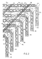
- FIG. 1 leads to a larger grid-like connection according to FIG. 2.
- vertically standing truss modules M1 supports or columns, which rest with feet 30 on an installation level and remove a grid-like truss structure on the top side via a flat articulated connection 31, in which the modules M 1 with larger cross width W 1 are penetrated by modules M 2 with smaller cross width W 2 are.
- spotlights 32 are connected on the lower busbars 10 of the modules M1 but also on the lower busbars 10 of the truss modules M2, spotlights 32 are connected.
- rope braces 33 can also be provided - in the present case running in a cross shape.
- spacer tubes 34 can be provided in the upper corner region. Instead of these spacer tubes 34, it is also possible, for example in the upper third of the column-like truss modules M 1, that is to say at the penetration points designated 35, to let truss modules M 2 pass through, the connecting crosses K 2 of which then extend in a horizontal plane would, while the smaller connecting crosses K2 shown in Fig. 2 extend in a vertical plane.
- the truss modules M1 each with four meters of axial individual length in the axial direction x follow each other, so that in this case the free span (portal width) in the direction x between two opposite joint supports 31 is twelve meters.
- FIG. 3 Analogously, a portal half is shown in the embodiment according to FIG. 3 jur.
- the portal shown in Fig. 3 allows a greater load capacity than the structure shown in Fig. 2.
- two identical truss modules or a succession of several interconnected truss modules M 1 are firmly connected to one another via smaller connecting crosses K 2.
- the connecting crosses K2 are arranged in inclined planes and screwed with their fastening feet 17 to corresponding struts 12 of two larger adjacent connecting crosses K1 of the two neighboring truss modules M1 at the fastening points 36.
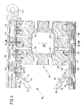
- FIG. 4 and 5 show in particular a plate-shaped connecting part 37, the fastening areas of which only one is identified by 38 are also arranged on the four corners of a square.
- FIG. 1 continuous filler pieces 19 can be seen from FIG. 4, each of which is penetrated by fastening screws 25, for which purpose the plate-shaped connecting part 37 has internal thread receptacles 39. So that additional thrust and tensile forces can be transmitted, there are additional internal thread mounts 40 socket head screws 41 are provided, the head area of which in each case passes through the profile base 28 of the conductor rail or a non-electrified, that is to say conductor-free, hollow profile rail 10a.
- a hanging arrangement of the truss module M 1 is provided in the representation according to FIG. the joint disks or joint eyes 42 of the flat joint connection 31 are each provided at the top.
- an articulated fork with articulated bolt which is fastened to the wall side of a building structure in a manner not shown.
- the joint eye 42 has a screw extension 43, which is held in the internal thread of a tubular insert, designated overall by 44.
- the tubular insert 44 itself has slot-like slots 45, 46 in its upper and lower regions, which are penetrated transversely by a screw bolt 47, the threaded end of which is held in an internal thread receptacle 48 of the plate-shaped connecting part 37.
- the stop 49 representing an extension protection against axial tolerance adjustments on the outside of the lower link slot 46.
- a box-shaped recess or opening 50 is provided, which is used to hold electrical connecting or control and regulating parts and, according to FIG. 5, can be closed on both sides with a cover 56.
- the plate-shaped connecting part 37 also has a number of cable bushings 51 for supply cables 57 (FIGS. 2 and 3) for feeding in the busbar 10.
- feed pieces are provided in their adapter receiving channel 21 (see FIG. 1), as are disclosed, for example, in DE-A-29 15 502. Such feed pieces are also located in the areas of the joints S on both sides of the end faces of the steel connecting pieces 27.
- FIG. 6 shows how the electrical connection in series of two busbars 10 which follow one another in the longitudinal direction takes place.
- the dash-dot and Line denoted by i symbolize one or more electrical lines.
- the electrical lines combined, for example, to form a cable i each open to the left and right of the steel connecting piece 27 in an electrical feed piece (see DE-OS 29 15 502).
- the electrical cable is guided below the steel connecting piece 27 through this and through the bottom 28 of the respective busbar 10 within cable bushings 52.
- a connection terminal arrangement is shown schematically and designated 60.
- the connecting terminal arrangement 60 is surrounded by an approximately double-trapezoidal switch housing 61, which consists of two essentially identical shell halves 62, 63, which are held firmly together by means of screws 64 penetrating the strut-side fastening bores 55.
- the two-shell switch housing 61 which is expediently made of light metal die-casting, also serves as a gusset-like stiffening of the joint area S.
- the arrangements according to the invention initially permit the structural design and then the electrical connection of the system with a minimum of work.
- FIG. 6 it can also be seen how two truss modules M2 are attached to each other in the area of the joint S and to a module M1.
- an Allen screw 65 passes from the adapter receptacle 21 from the lower busbar 10 of the larger truss module M 1 in succession to the following components:
- a washer 66 formally adapted to the undersurface of the busbar floor 28, the floor 28 itself, then the filler 19, finally penetrates the adapter receptacle channel 21 of the lower busbar 10 of the smaller truss module M2 and is then held in a threaded bore 67 of the steel connector 27.
- busbars 10 which have an essentially round cross section can of course also be used, as shown in DE-OS 29 15 502.
- busbars 10 themselves or the empty profiles 10a to accommodate light sources with appropriate dimensioning, that is to say they can generally serve as lamp holders or as lights.
- the slots it is also possible to use the slots to cover or conceal the hollow profiles 10, 10a, for example the adapter receiving channel 21, at desired points by means of a plastic or metal profile, if this appears expedient for optical or other reasons.
- a plate-shaped connecting part 37 is similar to that of a large or small connecting cross K1, K2.
- the plate-shaped connecting part 37 is also a light metal die-cast part; analog to the connecting crosses K1, K2 (see Fig. 1 and 3), the profile web with 15 and the profile flanges with 14 are designated.
Landscapes
- Engineering & Computer Science (AREA)
- General Engineering & Computer Science (AREA)
- Rod-Shaped Construction Members (AREA)
- Non-Portable Lighting Devices Or Systems Thereof (AREA)
- Installation Of Indoor Wiring (AREA)
- Arrangement Of Elements, Cooling, Sealing, Or The Like Of Lighting Devices (AREA)
Applications Claiming Priority (2)
| Application Number | Priority Date | Filing Date | Title |
|---|---|---|---|
| DE3808570A DE3808570A1 (de) | 1988-03-15 | 1988-03-15 | Fachwerkartige stromschienen-anordnung fuer beleuchtungszwecke |
| DE3808570 | 1988-03-15 |
Publications (2)
| Publication Number | Publication Date |
|---|---|
| EP0337016A1 EP0337016A1 (de) | 1989-10-18 |
| EP0337016B1 true EP0337016B1 (de) | 1994-04-27 |
Family
ID=6349750
Family Applications (1)
| Application Number | Title | Priority Date | Filing Date |
|---|---|---|---|
| EP88121475A Expired - Lifetime EP0337016B1 (de) | 1988-03-15 | 1988-12-22 | Fachwerkartige Stromschienen-Anordnung für Beleuchtungszwecke |
Country Status (4)
| Country | Link |
|---|---|
| EP (1) | EP0337016B1 (https=) |
| JP (1) | JPH0711922B2 (https=) |
| DE (2) | DE3808570A1 (https=) |
| ES (1) | ES2055732T3 (https=) |
Families Citing this family (5)
| Publication number | Priority date | Publication date | Assignee | Title |
|---|---|---|---|---|
| IT1265854B1 (it) * | 1993-03-05 | 1996-12-12 | Giampaolo Targetti | Struttura a rete in elementi componibili per illuminazione. |
| EP1415108A1 (de) * | 2001-07-24 | 2004-05-06 | Ezzat Attia | Tragsystem |
| JP3714546B2 (ja) * | 2001-12-28 | 2005-11-09 | 明治鋼業株式会社 | 建物の躯体構造 |
| DE202006006184U1 (de) * | 2006-04-18 | 2007-08-30 | Paul Hettich Gmbh & Co. Kg | Befestigung für Möbel |
| US11421418B2 (en) * | 2019-12-20 | 2022-08-23 | Universal City Studios Llc | Truss with integrated wiring |
Family Cites Families (5)
| Publication number | Priority date | Publication date | Assignee | Title |
|---|---|---|---|---|
| DE2810681C2 (de) * | 1978-03-11 | 1982-04-08 | Erco Leuchten GmbH, 5880 Lüdenscheid | Adapter für ein- oder mehrphasige Stromentnahmeschienen |
| FI58570C (fi) * | 1978-12-13 | 1981-02-10 | Nokia Oy Ab | Monteringsarrangemang foer kontaktskena |
| DE2915502C2 (de) * | 1979-04-17 | 1984-01-26 | Erco Leuchten GmbH, 5880 Lüdenscheid | Stromentnahmeschiene |
| EP0033769A3 (de) * | 1980-02-09 | 1981-11-25 | PEERLESS Elektronik GmbH | Kopfhörervorführeinrichtung |
| DE8410641U1 (de) * | 1984-04-05 | 1984-10-25 | Gierß, Karsten, 7000 Stuttgart | Scheinwerfertraverse |
-
1988
- 1988-03-15 DE DE3808570A patent/DE3808570A1/de active Granted
- 1988-12-22 ES ES88121475T patent/ES2055732T3/es not_active Expired - Lifetime
- 1988-12-22 EP EP88121475A patent/EP0337016B1/de not_active Expired - Lifetime
- 1988-12-22 DE DE3889325T patent/DE3889325D1/de not_active Expired - Fee Related
-
1989
- 1989-03-09 JP JP1055280A patent/JPH0711922B2/ja not_active Expired - Fee Related
Also Published As
| Publication number | Publication date |
|---|---|
| JPH01274611A (ja) | 1989-11-02 |
| ES2055732T3 (es) | 1994-09-01 |
| JPH0711922B2 (ja) | 1995-02-08 |
| DE3889325D1 (de) | 1994-06-01 |
| DE3808570C2 (https=) | 1990-02-01 |
| EP0337016A1 (de) | 1989-10-18 |
| DE3808570A1 (de) | 1989-09-28 |
Similar Documents
| Publication | Publication Date | Title |
|---|---|---|
| CH618237A5 (https=) | ||
| DE3802309C2 (https=) | ||
| DE3509721A1 (de) | Konstruktion fuer aussenaufbauten aus netzwerkbauteilen | |
| EP0337016B1 (de) | Fachwerkartige Stromschienen-Anordnung für Beleuchtungszwecke | |
| EP0169575A2 (de) | Rahmensystem, insbesondere für Gestelle und den Innenausbau | |
| DE2327078A1 (de) | Stromverteilerschiene fuer stromabnehmer, insbesondere adapter | |
| DE4307920A1 (de) | Profil-System | |
| DE69115196T2 (de) | Rasterdecke. | |
| DE3935385C2 (de) | Traverse für den industriellen Halterungsbau | |
| EP0867657B1 (de) | Leuchte | |
| DE19630807C1 (de) | Tragarm für Steuergeräte, Kommandogehäuse und dergleichen | |
| DE2850096C2 (de) | Halterung zum Verlegen von Leitungen, Stangen oder Strängen beliebigen Profils | |
| EP0583701B1 (de) | Schwenkbare Konsole | |
| DE3808145C2 (https=) | ||
| DE19626347C2 (de) | Oberleitung | |
| DE10124000B4 (de) | Decke eines Raumes in Bauwerken | |
| DE2623004A1 (de) | Anordnung zur verbindung von bauteilen von fachwerken oder geruesten | |
| DE3901222C2 (de) | Stranggepreßtes Kastenprofil | |
| DE3225115A1 (de) | Streckenausbau fuer den berg- und tunnelbau | |
| DE3335444C2 (de) | Verbindung zwischen einer Deichsel und einer Achse | |
| EP0141211A2 (de) | Fahrschiene für Einschienenhängebahn | |
| EP0337115A2 (de) | Leuchtenträger-Anordnung | |
| DE9215660U1 (de) | Hakentragsystem | |
| AT299377B (de) | Gehängter Deckenraster für Großräume | |
| DE1489558B2 (de) | Tragbügel zum Aufhängeil einer Straßenleuchte |
Legal Events
| Date | Code | Title | Description |
|---|---|---|---|
| PUAI | Public reference made under article 153(3) epc to a published international application that has entered the european phase |
Free format text: ORIGINAL CODE: 0009012 |
|
| 17P | Request for examination filed |
Effective date: 19890822 |
|
| AK | Designated contracting states |
Kind code of ref document: A1 Designated state(s): BE CH DE ES FR GB IT LI NL |
|
| 17Q | First examination report despatched |
Effective date: 19920819 |
|
| RBV | Designated contracting states (corrected) |
Designated state(s): DE ES FR GB |
|
| GRAA | (expected) grant |
Free format text: ORIGINAL CODE: 0009210 |
|
| AK | Designated contracting states |
Kind code of ref document: B1 Designated state(s): DE ES FR GB |
|
| REF | Corresponds to: |
Ref document number: 3889325 Country of ref document: DE Date of ref document: 19940601 |
|
| GBT | Gb: translation of ep patent filed (gb section 77(6)(a)/1977) |
Effective date: 19940505 |
|
| ET | Fr: translation filed | ||
| REG | Reference to a national code |
Ref country code: ES Ref legal event code: FG2A Ref document number: 2055732 Country of ref document: ES Kind code of ref document: T3 |
|
| PLBE | No opposition filed within time limit |
Free format text: ORIGINAL CODE: 0009261 |
|
| STAA | Information on the status of an ep patent application or granted ep patent |
Free format text: STATUS: NO OPPOSITION FILED WITHIN TIME LIMIT |
|
| 26N | No opposition filed | ||
| PGFP | Annual fee paid to national office [announced via postgrant information from national office to epo] |
Ref country code: DE Payment date: 20011109 Year of fee payment: 14 |
|
| REG | Reference to a national code |
Ref country code: GB Ref legal event code: IF02 |
|
| PGFP | Annual fee paid to national office [announced via postgrant information from national office to epo] |
Ref country code: GB Payment date: 20021210 Year of fee payment: 15 |
|
| PGFP | Annual fee paid to national office [announced via postgrant information from national office to epo] |
Ref country code: FR Payment date: 20021212 Year of fee payment: 15 |
|
| PGFP | Annual fee paid to national office [announced via postgrant information from national office to epo] |
Ref country code: ES Payment date: 20021223 Year of fee payment: 15 |
|
| PG25 | Lapsed in a contracting state [announced via postgrant information from national office to epo] |
Ref country code: DE Free format text: LAPSE BECAUSE OF NON-PAYMENT OF DUE FEES Effective date: 20030701 |
|
| PG25 | Lapsed in a contracting state [announced via postgrant information from national office to epo] |
Ref country code: GB Free format text: LAPSE BECAUSE OF NON-PAYMENT OF DUE FEES Effective date: 20031222 |
|
| PG25 | Lapsed in a contracting state [announced via postgrant information from national office to epo] |
Ref country code: ES Free format text: LAPSE BECAUSE OF NON-PAYMENT OF DUE FEES Effective date: 20031223 |
|
| GBPC | Gb: european patent ceased through non-payment of renewal fee |
Effective date: 20031222 |
|
| PG25 | Lapsed in a contracting state [announced via postgrant information from national office to epo] |
Ref country code: FR Free format text: LAPSE BECAUSE OF NON-PAYMENT OF DUE FEES Effective date: 20040831 |
|
| REG | Reference to a national code |
Ref country code: FR Ref legal event code: ST |
|
| REG | Reference to a national code |
Ref country code: ES Ref legal event code: FD2A Effective date: 20031223 |