EP0337016B1 - Framework-like bus bar device for lighting purpose - Google Patents
Framework-like bus bar device for lighting purpose Download PDFInfo
- Publication number
- EP0337016B1 EP0337016B1 EP88121475A EP88121475A EP0337016B1 EP 0337016 B1 EP0337016 B1 EP 0337016B1 EP 88121475 A EP88121475 A EP 88121475A EP 88121475 A EP88121475 A EP 88121475A EP 0337016 B1 EP0337016 B1 EP 0337016B1
- Authority
- EP
- European Patent Office
- Prior art keywords
- frame
- arrangement according
- busbar arrangement
- securing
- hollow section
- Prior art date
- Legal status (The legal status is an assumption and is not a legal conclusion. Google has not performed a legal analysis and makes no representation as to the accuracy of the status listed.)
- Expired - Lifetime
Links
Images


Classifications
-
- F—MECHANICAL ENGINEERING; LIGHTING; HEATING; WEAPONS; BLASTING
- F21—LIGHTING
- F21S—NON-PORTABLE LIGHTING DEVICES; SYSTEMS THEREOF; VEHICLE LIGHTING DEVICES SPECIALLY ADAPTED FOR VEHICLE EXTERIORS
- F21S2/00—Systems of lighting devices, not provided for in main groups F21S4/00 - F21S10/00 or F21S19/00, e.g. of modular construction
-
- F—MECHANICAL ENGINEERING; LIGHTING; HEATING; WEAPONS; BLASTING
- F21—LIGHTING
- F21V—FUNCTIONAL FEATURES OR DETAILS OF LIGHTING DEVICES OR SYSTEMS THEREOF; STRUCTURAL COMBINATIONS OF LIGHTING DEVICES WITH OTHER ARTICLES, NOT OTHERWISE PROVIDED FOR
- F21V21/00—Supporting, suspending, or attaching arrangements for lighting devices; Hand grips
- F21V21/34—Supporting elements displaceable along a guiding element
- F21V21/35—Supporting elements displaceable along a guiding element with direct electrical contact between the supporting element and electric conductors running along the guiding element
Definitions
- the invention relates to a truss-like busbar arrangement, as has become known from DE-A-29 15 502.
- two busbars are held together in an upright arrangement on the foot and head side by means of special foot and head connectors.
- Two such double-track busbars are fastened to one another via two equally long, horizontally extending binders composed of two half-shells. This is done in such a way that insert pieces provided at the end face of each binder engage in the slot of the busbar, that is to say in the adapter receiving channel, which, as is known, receives the relatively sensitive insulating material carrier containing copper conductor rails.
- the adapters of spotlights are plugged into the adapter receiving channel between the attachment points on the binder side and are intended to illuminate exhibits held on the binders, for example.
- the truss-like busbar arrangement known from DE-A-29 15 502 is both in terms of their load-bearing capacity and their usability are limited.
- this known truss-like busbar arrangement a basic way has already been shown of not only using busbars as a supporting element of lights, but also integrating them into a truss-like supporting structure.
- the invention is based on the object of further developing the known truss-type busbar arrangement so that, with expanded application options, it also has a significantly higher load capacity with the possibility of also having large spans free to bridge. This object has been achieved in accordance with the features of patent claim 1.
- the fastening grooves of the two hollow profiles face each other, the two fastening grooves serving to attach connecting parts which fasten the two hollow profiles to one another, the adapter receiving channel of the conductor rail is available solely for electrical feeding or removal purposes.
- the invention therefore creates a separation of the carrying or fastening function and the electrical supply function, the latter in particular of lights. In this way, both functions can not hinder each other, as is the case, for example, with the subject of DE-A-29 15 502.
- the adapter receiving channel serves both for current consumption by means of an adapter and for fastening two slotted tube-like hollow profiles of a pair of hollow profiles to one another.
- the conductor rail according to DE-A-29 15 502 has an axial fastening groove on its outside diametrically opposite the axial slot opening (adapter receiving channel), but this fastening groove only serves to hold fastening parts for the ceiling-side cable or pendulum tube holder, but not for fastening two Busbars to each other (S.DE-A-29 15 502 p.5 paragraph 3; p.9 paragraph 4) Fastening grooves on power rails are known per se from DE-C2-28 10 681.
- a rigid connecting part is created according to the invention have been, the fastening areas are arranged at least in a square, so - in contrast to the truss module according to DE-A-29 15 502 - are widely spaced apart in a statically favorable manner with respect to one and the same hollow profile.
- the rigid connecting part can either be plate-shaped or cross-shaped in accordance with other features of the invention, in particular in the manner of a St. Andrew's cross containing oblique struts.
- a truss module according to the invention is therefore constructed such that in the horizontal arrangement of such a module, in which, however, the two hollow profiles of the pair of hollow profiles lie vertically one above the other or next to one another (comparable to an I-beam), e.g. the upper hollow profile forms the compression belt when loaded and the lower hollow profile forms the tension belt.
- Truss modules according to the invention can be arranged axially one after the other and can be coupled to one another on the end faces of their hollow profiles in a tensile and compressive manner. By inserting tensile and pressure resistant into the hollow profiles and also fastened there insert pieces ensures that with the invention Truss modules can span very large spans.
- the truss modules according to the invention can overall form a truss structure or, in a parallel arrangement of similar truss modules next to one another, can form box-like supports with a corresponding cross connection.
- the truss modules according to the invention can be used, for example, to create portals or portal groups or truss-like ceiling structures.
- the truss modules according to the invention can be used with particular advantage in exhibition halls.
- individual room structures with an additional supporting function can be created, which allow even larger exhibits to be illuminated from all directions, in particular also from above - and also allow a room separation function.
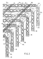
- a truss module with larger transverse width with M1 and a truss module with smaller transverse width are designated with M2.
- the truss modules M1, M2 (see M2 meet at the joints marked with S against each other.
- Each truss module M1 and M2 has a pair of hollow sections, which consists of two busbars 10. These busbars 10 are attached according to the different cross-sections W 1 (larger cross section) and W 2 (smaller cross section) by means of different connecting parts K 1, K 2 spaced apart.
- the connecting parts of the truss modules M1 are designated with K1 and the connecting parts of the truss modules M2 with K2.
- Each connecting part K1, K2 consists of two oblique struts 11, 12 arranged in the manner of a St. Andrew's cross, which are arranged in the same plane and represent an overall rigid component because of their integral, integral connection in the central node region 13.
- connecting crosses K1 large connecting cross
- K2 small connecting cross
- the connecting parts are integrally-integrally connected light metal die-cast parts, the cross section of the oblique struts 11, 12 being approximately I-shaped, as is e.g. 3, that is to say each has two flanges 14 and a web 15 connecting them.
- the webs 15 are provided with openings 16 (as in a Vendeel beam, for example).
- each fastening foot 17 carries at the end a foot plate 18 with a support surface 53, which is supported on a filler 19, which is accommodated relatively snugly in the approximately omega-shaped fastening groove 20 of the respective busbar 10 (see also hollow profile 10a of FIGS. 4 and 5) .
- each slotted tube-like busbar 10 has a slot, i. an adapter receiving channel 21.
- the adapter receiving channel 21 contains axially extending and oppositely arranged insulating material profiles 22, each of which receives a metal conductor, for example a copper flat conductor 23.
- a metal conductor for example a copper flat conductor 23.
- the fastening feet 17 of the connecting crosses K1 and K2 contain accessible internal thread receptacles 24 for fastening screws 25 from the support surface 53.
- the fastening screws 25 penetrate the bottom 26 of an elongated, approximately U-shaped Steel connector 27 and also the bottom 28 of the busbar 10 from the adapter receiving channel 21.
- the joints S are fastened to one another in the longitudinal direction x successive busbars 10 in a tensile and compressive manner, while at the same time a firm connection of great force absorption capacity is achieved between the mounting feet 17 and the omega-shaped mounting grooves 20 of the busbars 10.
- the steel connecting pieces 27 with cams 29 arranged above their base 26 correspondingly form coupling holes 59 of the same shape within the base 26.
- the coupling holes 59 are designated in more detail in FIG. 6 .
- FIG. 1 leads to a larger grid-like connection according to FIG. 2.
- vertically standing truss modules M1 supports or columns, which rest with feet 30 on an installation level and remove a grid-like truss structure on the top side via a flat articulated connection 31, in which the modules M 1 with larger cross width W 1 are penetrated by modules M 2 with smaller cross width W 2 are.
- spotlights 32 are connected on the lower busbars 10 of the modules M1 but also on the lower busbars 10 of the truss modules M2, spotlights 32 are connected.
- rope braces 33 can also be provided - in the present case running in a cross shape.
- spacer tubes 34 can be provided in the upper corner region. Instead of these spacer tubes 34, it is also possible, for example in the upper third of the column-like truss modules M 1, that is to say at the penetration points designated 35, to let truss modules M 2 pass through, the connecting crosses K 2 of which then extend in a horizontal plane would, while the smaller connecting crosses K2 shown in Fig. 2 extend in a vertical plane.
- the truss modules M1 each with four meters of axial individual length in the axial direction x follow each other, so that in this case the free span (portal width) in the direction x between two opposite joint supports 31 is twelve meters.
- FIG. 3 Analogously, a portal half is shown in the embodiment according to FIG. 3 jur.
- the portal shown in Fig. 3 allows a greater load capacity than the structure shown in Fig. 2.
- two identical truss modules or a succession of several interconnected truss modules M 1 are firmly connected to one another via smaller connecting crosses K 2.
- the connecting crosses K2 are arranged in inclined planes and screwed with their fastening feet 17 to corresponding struts 12 of two larger adjacent connecting crosses K1 of the two neighboring truss modules M1 at the fastening points 36.
- FIG. 4 and 5 show in particular a plate-shaped connecting part 37, the fastening areas of which only one is identified by 38 are also arranged on the four corners of a square.
- FIG. 1 continuous filler pieces 19 can be seen from FIG. 4, each of which is penetrated by fastening screws 25, for which purpose the plate-shaped connecting part 37 has internal thread receptacles 39. So that additional thrust and tensile forces can be transmitted, there are additional internal thread mounts 40 socket head screws 41 are provided, the head area of which in each case passes through the profile base 28 of the conductor rail or a non-electrified, that is to say conductor-free, hollow profile rail 10a.
- a hanging arrangement of the truss module M 1 is provided in the representation according to FIG. the joint disks or joint eyes 42 of the flat joint connection 31 are each provided at the top.
- an articulated fork with articulated bolt which is fastened to the wall side of a building structure in a manner not shown.
- the joint eye 42 has a screw extension 43, which is held in the internal thread of a tubular insert, designated overall by 44.
- the tubular insert 44 itself has slot-like slots 45, 46 in its upper and lower regions, which are penetrated transversely by a screw bolt 47, the threaded end of which is held in an internal thread receptacle 48 of the plate-shaped connecting part 37.
- the stop 49 representing an extension protection against axial tolerance adjustments on the outside of the lower link slot 46.
- a box-shaped recess or opening 50 is provided, which is used to hold electrical connecting or control and regulating parts and, according to FIG. 5, can be closed on both sides with a cover 56.
- the plate-shaped connecting part 37 also has a number of cable bushings 51 for supply cables 57 (FIGS. 2 and 3) for feeding in the busbar 10.
- feed pieces are provided in their adapter receiving channel 21 (see FIG. 1), as are disclosed, for example, in DE-A-29 15 502. Such feed pieces are also located in the areas of the joints S on both sides of the end faces of the steel connecting pieces 27.
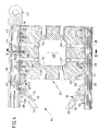
- FIG. 6 shows how the electrical connection in series of two busbars 10 which follow one another in the longitudinal direction takes place.
- the dash-dot and Line denoted by i symbolize one or more electrical lines.
- the electrical lines combined, for example, to form a cable i each open to the left and right of the steel connecting piece 27 in an electrical feed piece (see DE-OS 29 15 502).
- the electrical cable is guided below the steel connecting piece 27 through this and through the bottom 28 of the respective busbar 10 within cable bushings 52.
- a connection terminal arrangement is shown schematically and designated 60.
- the connecting terminal arrangement 60 is surrounded by an approximately double-trapezoidal switch housing 61, which consists of two essentially identical shell halves 62, 63, which are held firmly together by means of screws 64 penetrating the strut-side fastening bores 55.
- the two-shell switch housing 61 which is expediently made of light metal die-casting, also serves as a gusset-like stiffening of the joint area S.
- the arrangements according to the invention initially permit the structural design and then the electrical connection of the system with a minimum of work.
- FIG. 6 it can also be seen how two truss modules M2 are attached to each other in the area of the joint S and to a module M1.
- an Allen screw 65 passes from the adapter receptacle 21 from the lower busbar 10 of the larger truss module M 1 in succession to the following components:
- a washer 66 formally adapted to the undersurface of the busbar floor 28, the floor 28 itself, then the filler 19, finally penetrates the adapter receptacle channel 21 of the lower busbar 10 of the smaller truss module M2 and is then held in a threaded bore 67 of the steel connector 27.
- busbars 10 which have an essentially round cross section can of course also be used, as shown in DE-OS 29 15 502.
- busbars 10 themselves or the empty profiles 10a to accommodate light sources with appropriate dimensioning, that is to say they can generally serve as lamp holders or as lights.
- the slots it is also possible to use the slots to cover or conceal the hollow profiles 10, 10a, for example the adapter receiving channel 21, at desired points by means of a plastic or metal profile, if this appears expedient for optical or other reasons.
- a plate-shaped connecting part 37 is similar to that of a large or small connecting cross K1, K2.
- the plate-shaped connecting part 37 is also a light metal die-cast part; analog to the connecting crosses K1, K2 (see Fig. 1 and 3), the profile web with 15 and the profile flanges with 14 are designated.
Landscapes
- Engineering & Computer Science (AREA)
- General Engineering & Computer Science (AREA)
- Rod-Shaped Construction Members (AREA)
- Non-Portable Lighting Devices Or Systems Thereof (AREA)
- Installation Of Indoor Wiring (AREA)
- Arrangement Of Elements, Cooling, Sealing, Or The Like Of Lighting Devices (AREA)
Description
Die Erfindung betrifft eine fachwerkartige Stromschienen-Anordnung, wie sie durch die DE-A-29 15 502 bekanntgeworden ist.The invention relates to a truss-like busbar arrangement, as has become known from DE-A-29 15 502.
Bei der fachwerkartigen Stromschienen-Anordnung gemäß DE-A-29 15 502 sind jeweils zwei Stromschienen in aufrechter Anordnung fuß- und kopfseitig über besondere Fuß- und Kopfverbindungsstücke aneinandergehalten. Zwei derartige Stromschienen-Doppelsäulen sind über zwei gleichlange sich horizontal erstreckende, aus zwei Halbschalen zusammengesetzte Binder aneinander befestigt. Dieses geschieht so, daß endstirnseitig eines jeden Binders vorgesehene Einsatzstücke in den Schlitz der Stromschiene, also in den Adapteraufnahmekanal eingreifen, welcher bekanntlich die Kupfer-Leiterschienen enthaltenden, relativ empfindlichen Isolierstoffträger aufnimmt. Zwischen den binderseitigen Befestigungsstellen sind die Adapter von Strahlerleuchten in den Adapteraufnahmekanal eingesteckt, welche dazu dienen sollen, beispielsweise an den Bindern gehaltene Exponate zu beleuchten.In the framework-like busbar arrangement according to DE-A-29 15 502, two busbars are held together in an upright arrangement on the foot and head side by means of special foot and head connectors. Two such double-track busbars are fastened to one another via two equally long, horizontally extending binders composed of two half-shells. This is done in such a way that insert pieces provided at the end face of each binder engage in the slot of the busbar, that is to say in the adapter receiving channel, which, as is known, receives the relatively sensitive insulating material carrier containing copper conductor rails. The adapters of spotlights are plugged into the adapter receiving channel between the attachment points on the binder side and are intended to illuminate exhibits held on the binders, for example.
Die durch die DE-A-29 15 502 bekannte fachwerkartige Stromschienen-Anordnung ist sowohl hinsichtlich ihrer Tragfähigkeit als auch hinsichtlich ihrer Verwendungsfähigkeit begrenzt. Indes wurde mit dieser bekannten fachwerkartigen Stromschienen-Anordnung bereits ein grundsätzlicher Weg gewiesen, Stromschienen nicht nur als Tragelement von Leuchten zu benutzen, sondern darüber hinaus in eine fachwerkartige Tragkonstruktion einzugliedern.The truss-like busbar arrangement known from DE-A-29 15 502 is both in terms of their load-bearing capacity and their usability are limited. In the meantime, with this known truss-like busbar arrangement, a basic way has already been shown of not only using busbars as a supporting element of lights, but also integrating them into a truss-like supporting structure.
Ausgehend von der fachwerkartigen Stromschienen-Anordnung gemäß der DE-A-29 15 502, liegt der Erfindung die Aufgabe zugrunde, die bekannte fachwerkartige Stromschienen-Anordnung so weiterzuentwickeln, daß diese bei erweiterten Anwendungsmöglichkeiten zugleich eine wesentlich höhere Tragfähigkeit mit der Möglichkeit, auch große Spannweiten frei zu überbrücken, besitzt. Diese Aufgabe ist entsprechend den Merkmalen des Patentanspruchs 1 gelöst worden.Starting from the truss-like busbar arrangement according to DE-A-29 15 502, the invention is based on the object of further developing the known truss-type busbar arrangement so that, with expanded application options, it also has a significantly higher load capacity with the possibility of also having large spans free to bridge. This object has been achieved in accordance with the features of patent claim 1.
Dadurch, daß entsprechend der Erfindung die Befestigungsnuten der beiden Hohlprofile einander zugekehrt sind, wobei die beiden Befestigungsnuten der Anbringung von die beiden Hohlprofile aneinander befestigenden Verbindungsteilen dienen, steht der Adapteraufnahmekanal der Stromschiene allein elektrischen Einspeisungs- oder Entnahmezwecken zur Verfügung. Die Erfindung schafft daher eine Trennung von Trag- bzw. Befestigungsfunktion und elektrischer Versorgungsfunktion, letztere insbesondere von Leuchten. Auf diese Weise können beide Funktionen einander nicht behindern, wie es z.B. beim Gegenstand der DE-A-29 15 502 der Fall ist. Dort dient nämlich der Adapteraufnahmekanal sowohl der Stromentnahme mittels eines Adapters als auch der Befestigung zweier schlitzrohrartiger Hohlprofile eines Hohlprofilpaars aneinander.Characterized in that, according to the invention, the fastening grooves of the two hollow profiles face each other, the two fastening grooves serving to attach connecting parts which fasten the two hollow profiles to one another, the adapter receiving channel of the conductor rail is available solely for electrical feeding or removal purposes. The invention therefore creates a separation of the carrying or fastening function and the electrical supply function, the latter in particular of lights. In this way, both functions can not hinder each other, as is the case, for example, with the subject of DE-A-29 15 502. There, namely, the adapter receiving channel serves both for current consumption by means of an adapter and for fastening two slotted tube-like hollow profiles of a pair of hollow profiles to one another.
Entsprechend der Erfindung können demnach ungehindert von druckempfindlichen Isolierstoffträgern in den hohlprofilseitigen rein metallischen Befestigungsnuten wesentlich größere Kräfte übertragen werden, als dies beim Gegenstand der DE-A-29 15 502 möglich ist. Die Stromschiene entsprechend der DE-A-29 15 502 weist zwar an ihrer der axialen Schlitzöffnung (Adapteraufnahmekanal) diametral gegenüberliegenden Außenseite eine axiale Befestigungsnut auf, jedoch dient diese Befestigungsnut lediglich der Aufnahme von Befestigungsteilen zur deckenseitigen Seil- oder Pendelrohrhalterung, nicht aber der Befestigung zweier Stromschienen aneinander (S.DE-A-29 15 502 S.5 Abs. 3; S.9 Abs.4) Befestigungsnuten an Stromsihienen sind durch die DE-C2-28 10 681 an sich bekannt.According to the invention, therefore, much greater forces can be transmitted unhindered by pressure-sensitive insulating material carriers in the purely metallic fastening grooves on the hollow profile side than is possible with the subject of DE-A-29 15 502. The conductor rail according to DE-A-29 15 502 has an axial fastening groove on its outside diametrically opposite the axial slot opening (adapter receiving channel), but this fastening groove only serves to hold fastening parts for the ceiling-side cable or pendulum tube holder, but not for fastening two Busbars to each other (S.DE-A-29 15 502 p.5 paragraph 3; p.9 paragraph 4) Fastening grooves on power rails are known per se from DE-C2-28 10 681.
Im Unterschied zu dem aus zwei Stromschienen und zwei Querbindern bestehenden, seinerzeit für begrenzte Einsatzzwecke zwar hinreichenden, ansonsten aber relativ labilen Fachwerk-Modul entsprechend der DE-A-29 15 502 ist entsprechend der Erfindung ein starres Verbindungsteil geschaffen worden, dessen Befestigungsbereiche mindestens im Viereck angeordnet sind, also - im Unterschied zum Fachwerk-Modul gemäß der DE-A-29 15 502 - bezüglich ein- und desselben Hohlprofils in statisch günstiger Weise weit auseinanderliegen. Das starre Verbindungsteil kann entweder plattenförmig oder aber entsprechend anderen Erfindungsmerkmalen kreuzförmig, insbesondere nach der Art eines Schrägstreben enthaltenden Andreaskreuzes, ausgebildet sein.In contrast to the existing from two busbars and two bow ties, at the time sufficient for limited use, but otherwise relatively unstable truss module according to DE-A-29 15 502, a rigid connecting part is created according to the invention have been, the fastening areas are arranged at least in a square, so - in contrast to the truss module according to DE-A-29 15 502 - are widely spaced apart in a statically favorable manner with respect to one and the same hollow profile. The rigid connecting part can either be plate-shaped or cross-shaped in accordance with other features of the invention, in particular in the manner of a St. Andrew's cross containing oblique struts.
Ein erfindungsgemäßes Fachwerk-Modul ist daher so aufgebaut, daß in horizontaler Anordnung eines solches Moduls, bei welchem jedoch die beiden Hohlprofile des Hohlprofilpaars vertikal übereinander- oder nebeneinanderliegen (vergleichbar einem I-Träger) z.B. das obere Hohlprofil bei Belastung den Druckgurt und das untere Hohlprofil den Zuggurt bildet.A truss module according to the invention is therefore constructed such that in the horizontal arrangement of such a module, in which, however, the two hollow profiles of the pair of hollow profiles lie vertically one above the other or next to one another (comparable to an I-beam), e.g. the upper hollow profile forms the compression belt when loaded and the lower hollow profile forms the tension belt.
Derartige erfindungsgemäße Fachwerk-Module können axial aufeinanderfolgend angeordnet und hierbei an den Stirnseiten ihrer Hohlprofile zug- und druckfest miteinander gekuppelt sein. Durch zug- und druckfest in die Hohlprofile eingesteckte und dort außerdem befestigte Einsatzstücke ist gewährleistet, daß mit den erfindungsgemäßen Fachwerk-Modulen sehr große Spannweiten überbrückt werden können.Such truss modules according to the invention can be arranged axially one after the other and can be coupled to one another on the end faces of their hollow profiles in a tensile and compressive manner. By inserting tensile and pressure resistant into the hollow profiles and also fastened there insert pieces ensures that with the invention Truss modules can span very large spans.
Die erfindungsgemäßen Fachwerk-Module können insgesamt eine fachwerkartige Rasterstruktur oder aber - in Parallelanordnung gleichartiger Fachwerk-Module nebeneinander - bei entsprechender Querverbindung kastenartige Träger bilden. Mit den erfindungsgemäßen Fachwerk-Modulen können beispielsweise Portale bzw. Portalgruppen oder auch fachwerkartige Deckengebilde geschaffen werden. Die erfindungsgemäßen Fachwerk-Module lassen sich mit besonderem Vorteil in Ausstellungshallen anwenden. Hier können mit den erfindungsgemäßen Fachwerk-Modulen individuelle Raumstrukturen mit zusätzlicher Tragfunktion geschaffen werden, die eine Beleuchtung selbst größerer Exponate von allen Richtungen, insbesondere auch von oben her - und außerdem eine Raumtrennfunktion erlauben.The truss modules according to the invention can overall form a truss structure or, in a parallel arrangement of similar truss modules next to one another, can form box-like supports with a corresponding cross connection. The truss modules according to the invention can be used, for example, to create portals or portal groups or truss-like ceiling structures. The truss modules according to the invention can be used with particular advantage in exhibition halls. Here, with the truss modules according to the invention, individual room structures with an additional supporting function can be created, which allow even larger exhibits to be illuminated from all directions, in particular also from above - and also allow a room separation function.
Weitere Erfindungsmerkmale sind den Unteransprüchen zu entnehmen.Further features of the invention can be found in the subclaims.
In den Zeichnungen sind bevorzugte Ausführungsbeispiele entsprechend der Erfindung näher dargestellt, es zeigen:
- Fig. 1 einen Teilbereich einer fachwerkartigen Stromschienen-Anordnung, bei welcher sich Fachwerk-Module zweier unterschiedlicher Querweiten an einer Stoßstelle zwischen zwei Modulen quer durchdringen, und zwar etwa entsprechend einer in Fig. 2 gestrichelt angedeuteten Einkreisung in Blickrichtung des mit I bezeichneten Ansichtspfeils, wobei
- Fig. 2 in perspektivischer Darstellung einen Teilbereich einer etwa rasterartigen Fachwerkstruktur mit Säulenauflagerung zeigt,
- Fig. 3 einen Teilbereich eines Portals einer etwa kastenartigen Fachwerkstruktur,
- Fig. 4 einen teilweisen Vertikalschnitt etwa entsprechend der in Fig. 3 mit IV bezeichneten Einkreisung, wobei jedoch in Fig. 4 eine um 180° um die Längsachse x eines Fachwerk-Moduls gedrehte Anordnung gezeigt ist,
- Fig. 5 einen Schnitt etwa entsprechend der in Fig. 4 mit V-V bezeichneten Schnittlinie, und
- Fig. 6 in Anlehnung an die Darstellung gemäß Fig. 1 eine elektrische Einspeisung im Bereich einer Stoßstelle zwischen Stromschienen.
- Fig. 1 shows a portion of a truss-like busbar arrangement, in which truss modules of two different widths cross at a joint between two modules penetrate, approximately in accordance with an encirclement indicated by dashed lines in FIG. 2 in the direction of view of the view arrow labeled I, wherein
- 2 shows a perspective view of a partial area of an approximately grid-like truss structure with pillar support,
- 3 shows a partial area of a portal of an approximately box-type truss structure,
- 4 shows a partial vertical section roughly corresponding to the encirclement designated IV in FIG. 3, but in FIG. 4 an arrangement rotated by 180 ° about the longitudinal axis x of a truss module is shown,
- 5 shows a section approximately corresponding to the section line designated VV in FIG. 4, and
- FIG. 6, based on the illustration according to FIG. 1, shows an electrical feed in the region of a joint between busbars.
In Fig. 1 sind ein Fachwerk-Modul größerer Querweite mit M₁ und ein Fachwerk-Modul geringerer Querweite mit M₂ bezeichnet. Die Fachwerk-Module M₁, M₂ (s. M₂ stoßen an den mit S bezeichneten Stoßstellen gegeneinander.In Fig. 1, a truss module with larger transverse width with M₁ and a truss module with smaller transverse width are designated with M₂. The truss modules M₁, M₂ (see M₂ meet at the joints marked with S against each other.
Jedes Fachwerk-Modul M₁ und M₂ weist ein Hohlprofilpaar auf, welches aus zwei Stromschienen 10 besteht. Diese Stromschienen 10 werden entsprechend den unterschiedlichen Querweiten W₁ (größere Querweite) und W₂ (geringere Querweite) mittels unterschiedlicher Verbindungsteilen K₁, K₂ voneinander distanziert befestigt. Die Verbindungsteile der Fachwerk-Module M₁ sind mit K₁ und die Verbindungsteile der Fachwerk-Module M₂ mit K₂ bezeichnet.Each truss module M₁ and M₂ has a pair of hollow sections, which consists of two
Jedes Verbindungsteil K₁, K₂ besteht aus zwei nach Art eines Andreaskreuzes angeordneten Schrägstreben 11, 12, welche in derselben Ebene angeordnet sind und wegen ihrer im mittigen Knotenbereich 13 einstückig-stoffschlüssigen Verbindung ein insgesamt starres Bauteil darstellen.Each connecting part K₁, K₂ consists of two
Die demnach als Verbindungskreuze K₁ (großes Verbindungskreuz) und K₂ (kleineres Verbindungskreuz) ausgebildeten Verbindungsteile sind einstückig-stoffschlüssig zusammenhängende Leichtmetall-Druckgußteile, wobei der Querschnitt der Schrägstreben 11, 12 etwa I-förmig gestaltet ist, wie man z.B. anhand von Fig. 3 erkennen kann, also jeweils zwei Flansche 14 und einen diese miteinander verbindenden Steg 15 aufweist. Zwecks Gewichts- und Werkstoffersparnis sind die Stege 15 mit Durchbrechungen 16 (etwa wie bei einem Vierendeel-Träger) versehen.The connecting parts thus formed as connecting crosses K₁ (large connecting cross) and K₂ (smaller connecting cross) are integrally-integrally connected light metal die-cast parts, the cross section of the
Obwohl in Fig. 1 die Verbindungskreuze K₁, K₂ nicht zur Gänze dargestellt sind, ist anhand des rechts in Fig. 1 teilweise dargestellten Verbindungskreuzes K₂ vorstellbar, daß dieses jeweils beidendig seiner Schrägstreben 11, 12 auf den Ecken eines Vierecks angeordnete Befestigungsbereiche, und zwar Befestigungsfüße 17 aufweist. Jeder Befestigungsfuß 17 trägt endseitig eine Fußplatte 18 mit einer Stützfläche 53, welche sich auf einem Füllstück 19 abstützt, das jeweils verhältnismäßig satt in der etwa omega-förmigen Befestigungsnut 20 der jeweiligen Stromschiene 10 (s.a. Hohlprofil 10a der Fig. 4 und 5) aufgenommen ist.Although the crosses K₁, K₂ are not shown in full in Fig. 1, is based on the Connection cross K₂ partially shown on the right in FIG. 1 conceivable that this has fastening areas arranged on both ends of its
Der omega-förmigen Befestigungsnut 20 diametral gegenüber weist jede schlitzrohrartige Stromschiene 10 einen Schlitz, d.h. einen Adapteraufnahmekanal 21, auf. Der Adapteraufnahmekanal 21 enthält sich axial erstreckende und einander gegenüberliegend angeordnete Isolierstoffprofile 22, welche jeweils einen Metalleiter, beispielsweise einen Kupfer-Flachleiter 23, aufnehmen. Sowohl derartige Stromschienen 10 als auch entsprechende Adapter sind beispielsweise durch die DE-PS 28 10 681 vorbekannt.Diametrically opposite the omega-
Die Befestigungsfüße 17 der Verbindungskreuze K₁ und K₂ enthalten von der Stützfläche 53 her zugängliche Innengewindeaufnahmen 24 für Befestigungsschrauben 25 auf. Wie anhand von Fig. 1 zu ersehen, durchsetzen die Befestigungsschrauben 25 den Boden 26 eines länglichen etwa U-förmigen Stahl-Verbindungsstückes 27 und auch den Boden 28 der Stromschiene 10 vom Adapteraufnahmekanal 21 her. Auf diese Weise werden die Stöße S von in Längsrichtung x aufeinanderfolgenden Stromschienen 10 zug- und druckfest aneinander befestigt, während zugleich eine feste Verbindung großer Kraftaufnahmefähigkeit zwischen den Befestigungsfüßen 17 und den omega-förmigen Befestigungsnuten 20 der Stromschienen 10 zustandekommt. Um die zug- und druckfeste Verbindung im Stoßbereich S zwischen zwei aufeinanderfolgenden Stromschienen 10 zusätzlich zu erhöhen, durchsetzen die Stahlverbindungsstücke 27 mit oberhalb ihres Bodens 26 angeordneten Nocken 29 entsprechend formgleiche Kupplungslöcher 59 innerhalb des Bodens 26. Die Kupplungslöcher 59 sind in Fig. 6 näher bezeichnet.The fastening
Die Detailanordnung gemäß Fig. 1 führt entsprechend Fig. 2 zu einem größeren rasterförmigen Zusammenhang. Und zwar bilden vertikal stehende Fachwerk-Module M₁ Stützen bzw. Säulen, welche mit Füßen 30 auf einer Aufstellebene ruhen und oberseitig über eine ebene Gelenkverbindung 31 eine rasterartige Fachwerkstruktur abtragen, bei welcher jeweils die Module M₁ größerer Querweite W₁ von Modulen M₂ geringerer Querweite W₂ durchdrungen sind. An den unteren Stromschienen 10 der Module M₁ aber auch an den unteren Stromschienen 10 der Fachwerk-Module M₂ sind Strahlerleuchten 32 angeschlossen.The detailed arrangement according to FIG. 1 leads to a larger grid-like connection according to FIG. 2. Specifically, vertically standing truss modules M₁ supports or columns, which rest with
Zur Versteifung der rasterartigen Fachwerkstruktur gemäß Fig. 2 können zudem - im vorliegenden Falle kreuzförmig verlaufende - Seilverspannungen 33 vorgesehen sein.To reinforce the grid-like truss structure according to FIG. 2,
Zwischen den einzelnen portalartigen Gebilden gemäß Fig. 2, die unter anderem jeweils aus senkrecht und horizontal angeordneten Fachwerk-Modulen M₁ bestehen, können im oberen Eckbereich Distanzrohre 34 vorgesehen sein. Anstelle dieser Distanzrohre 34 ist es auch möglich, beispielsweise im oberen Drittel der aufgehend stützenartig angeordneten Fachwerk-Module M₁, also etwa an den mit 35 bezeichneten Durchdringungsstellen, Fachwerk-Module M₂ durchlaufen zu lassen, deren Verbindungskreuze K₂ sich dann allerding in einer horizontalen Ebene erstrecken würden, während die in Fig. 2 eingezeichneten kleineren Verbindungskreuze K₂ sich in einer vertikalen Ebene erstrecken.2, which among other things each consist of vertically and horizontally arranged truss modules M 1,
Gemäß Fig. 2 können jeweils die Fachwerk-Module M₁ mit je vier Meter axialer Einzellänge in Axialrichtung x aufeinanderfolgen, so daß in diesem Falle die frei Spannweite (Portalweite) in Richtung x zwischen zwei gegenüberliegenden Gelenk-Auflagern 31 zwölf Meter beträgt.2, the truss modules M₁ each with four meters of axial individual length in the axial direction x follow each other, so that in this case the free span (portal width) in the direction x between two opposite joint supports 31 is twelve meters.
Hinzugefügt werden muß noch, daß bei der Darstellung gemäß Fig. 2 aus Gründen einer Zeichnungsvereinfachung nur die rechten Portalseiten dargestellt sind.It must also be added that in the illustration according to FIG. 2 only the right portal pages are used to simplify the drawing are shown.
Analog ist beim Ausführungsbeispiel gemäß Fig. 3 jur eine Portalhälfte dargestellt. Das in Fig. 3 gezeigte Portal gestattet eine größere Tragfähigkeit als die in Fig. 2 dargestellte Struktur. Beim Ausführungsbeispiel gemäß Fig. 3 sind nämlich jeweils zwei gleichartige Fachwerk-Module bzw. eine Aufeinanderfolge von mehreren miteinander verbundenen Fachwerk-Modulen M₁ über kleinere Verbindungskreuze K₂ fest miteinander verbunden. Die Verbindungskreuze K₂ sind hierbei in schrägen Ebenen angeordnet und mit ihren Befestigungsfüßen 17 an korrespondierenden Streben 12 zweier größerer benachbarter Verbindungskreuze K₁ der beiden benachbarten Fachwerk-Module M₁ an den Befestigungsstellen 36 verschraubt. Hierzu weisen die Verbindungskreuze K₁ Befestigungsbohrungen auf, wie sie etwa den mit 55 bei K₂ in Fig. 1 bezeichneten entsprechen.Analogously, a portal half is shown in the embodiment according to FIG. 3 jur. The portal shown in Fig. 3 allows a greater load capacity than the structure shown in Fig. 2. In the exemplary embodiment according to FIG. 3, two identical truss modules or a succession of several interconnected truss modules M 1 are firmly connected to one another via smaller connecting crosses K 2. The connecting crosses K₂ are arranged in inclined planes and screwed with their
Aus den Fig. 4 und 5 geht insbesondere ein plattenförmiges Verbindungsteil 37 hervor, dessen Befestigungsbereiche, von denen nur einer mit 38 gekennzeichnet ist, ebenfalls auf den vier Ecken eines Vierecks angeordnet sind. Analog zu Fig. 1 sind aus Fig. 4 durchgehende Füllstücke 19 zu ersehen, welche jeweils von Befestigungsschrauben 25 durchsetzt sind, wozu das plattenförmige Verbindungsteil 37 Innengewindeaufnahmen 39 aufweist. Damit zusätzlich noch Schub- und Zugkräfte übertragen werden können, sind in weiteren Innengewindeaufnahmen 40 Schaftschrauben 41 vorgesehen, deren Kopfbereich jeweils den Profilboden 28 der Stromschiene bzw. einer nicht elektrifizierten, also leiterlosen, Hohlprofilschiene 10a durchsetzt.4 and 5 show in particular a plate-shaped connecting
Im Unterschied zur Darstellung gemäß den Fig. 2 und 3 ist bei der Darstellung gemäß Fig. 4 eine hängende Anordnung des Fachwerk-Moduls M₁ vorgesehen, d.h. die Gelenkscheiben bzw. Gelenkaugen 42 der ebenen Gelenkverbindung 31 sind jeweils oben vorgesehen. Komplementär zum Gelenkauge 42 kann man sich eine Gelenkgabel (mit Gelenkbolzen) vorstellen, welche in nicht gezeigter Weise wandseitig eines Baukörpers befestigt ist.In contrast to the representation according to FIGS. 2 and 3, a hanging arrangement of the truss module M 1 is provided in the representation according to FIG. the joint disks or
Das Gelenkauge 42 weist einen Schraubbolzenfortsatz 43 auf, welcher im Innengewinde eines insgesamt mit 44 bezeichneten rohrförmigen Einsatzes gehalten ist. Der rohrförmige Einsatz 44 selbst weist jeweils in seinem oberen und unteren Bereich kulissenartige Schlitze 45, 46 auf, welche von einem Schraubbolzen 47 quer durchgriffen sind, dessen Gewindeende in einer Innengewindeaufnahme 48 des plattenförmigen Verbindungsteils 37 gehalten ist. Auf diese Weise läßt sich eine sichere Klemmverbindung des rohrförmigen Einsatzes 44 mit dem Hohlprofil 10a herstellen, wobei der Anschlag 49 außenendseitig des unteren Kulissenschlitzes 46 bei axialen Toleranzanpassungen eine Auszugssicherung darstellt.The
In der Mitte des plattenförmigen Verbindungsteils 37 ist eine kastenförmige Ausnehmung bzw. Durchbrechung 50 vorgesehen, welche der Aufnahme von elektrischen Verbindungs- bzw. Steuer- und Regelteilen dienen und entsprechend Fig. 5 beidseitig mit je einem Deckel 56 geschlossen sein kann. Das plattenförmige Verbindungsteil 37 weist zudem eine Anzahl von Kabeldurchführungen 51 für Versorgungskabel 57 (Fig. 2 und 3) zur Einspeisung der Stromschiene 10 auf. Zur Einspeisung der Stromschiene 10 sind in deren Adapteraufnahmekanal 21 (s. Fig. 1) nicht dargestellte Einspeisstücke vorgesehen, wie sie beispielsweise in der DE-A-29 15 502 offenbart sind. Derartige Einspeisstücke befinden sich auch in den Bereichen der Stoßstellen S beiderseits der Stirnflächen der Stahlverbindungsstücke 27. Zur Hintereinanderschaltung zweier aufeinanderfolgender Stromschienen 10 unterschiedlicher Module M₁ bzw. M₂ sind in den Befestigungsfüßen 17 der Verbindungskreuze K₁, K₂ ebenfalls Kabeldurchführungen 52 vorgesehen, über die eine elektrische Leiterverbindung bzw. eine Überbrückung von nicht dargestellten Einspeisstücken gewährleistet ist, welche - wie erwähnt - links und rechts des jeweiligen Stahlverbindungsstückes 27 innerhalb des Adapteraufnahmekanals 21 der Stromschiene 10 angeordnet sind. In Fig. 6 ist dargestellt, wie die elektrische Hintereinanderschaltung zweier in Längsrichtung aufeinanderfolgender Stromschienen 10 geschieht. Hierbei soll die strichpunktierte und mit i bezeichnete Linie eine bzw. mehrere elektrische Leitungen symbolisieren. Die beispielsweise zu einem Kabel i zusammengefaßten elektrischen Leitungen münden jeweils links und rechts des Stahlverbindungsstückes 27 in einem elektrischen Einspeisstück (s. DE-OS 29 15 502). Das elektrische Kabel wird unterhalb des Stahlverbindungsstückes 27 durch dieses und den Boden 28 der jeweiligen Stromschiene 10 hindurch innerhalb von Kabeldurchführungen 52 geführt. Außerhalb der Stoßstelle S ist eine Verbindungsklemmen-Anordnung schematisch dargestellt und mit 60 bezeichnet.In the middle of the plate-shaped connecting
Die Verbindungsklemmenanordnung 60 ist von einem etwa doppeltrapezförmigen Schaltgehäuse 61 umgeben, welches aus zwei einander im wesentlichen identischen Schalenhälften 62, 63 besteht, die mittels zugleich die strebenseitigen Befestigungsbohrungen 55 durchsetzender Schrauben 64 fest aneinander gehalten sind. Auf diese Weise dient das zweckmäßig aus Leichtmetalldruckguß hergestellte zweischalige Schaltgehäuse 61 zugleich einer etwa knotenblechartigen Versteifung des Stoßstellenbereichs S. Über nicht dargestellte Anschlußkabel, die durch Öffnungen 68 des Schaltgehäuses 61 nach außen und sodann z.B. durch eine Durchführung 51 zum Schaltgehäuse 50 eines Verbindungsteiles 37 verlaufen können, kann die Stromversorgung bewerkstelligt werden. Die erfindungsgemäßen Anordnungen gestatten jedenfalls zunächst den strukturellen Aufbau und anschließend mit einem Minimum an Arbeit die elektrische Durchschaltung des Systems.The connecting
Aus Fig. 6 ist auch zu ersehen, wie zwei Fachwerk-Module M₂ im Bereich der Stoßstelle S aneinander und an einem Modul M₁ befestigt sind. Und zwar durchsetzt ein Innensechskant-Schraubbolzen 65 vom Adapteraufnahmekanal 21 her der unteren Stromschiene 10 des größeren Fachwerk-Moduls M₁ nacheinander folgende Bauteile: Eine an die Unterfläche des Stromschienenbodens 28 formlich angepaßte Unterlegscheibe 66, den Boden 28 selbst, sodann das Füllstück 19, durchsetzt schließlich den Adapteraufnahme-Kanal 21 der unteren Stromschiene 10 des kleineren Fachwerkmoduls M₂ und ist sodann in einer Gewindebohrung 67 des Stahlverbindungsstückes 27 gehalten.From Fig. 6 it can also be seen how two truss modules M₂ are attached to each other in the area of the joint S and to a module M₁. In fact, an
Anstelle der in den Fig. 1 und 3 dargestellten Flügel-Stromschienen 10 mit etwa rechteckigem Querschnitt können selbstverständlich auch Stromschienen verwendet werden, die einen im wesentlichen runden Querschnitt besitzen, wie in der DE-OS 29 15 502 dargestellt. Des weiteren ist es grundsätzlich möglich, daß die Stromschienen 10 selbst oder die Leerprofile 10a bei entsprechender Dimensionierung Lichtquellen aufnehmen, also allgemein als Lampenträger bzw. als Leuchten dienen können. Auch ist es möglich, die Schlitze der Hohlprofile 10, 10a, z.B. den Adapteraufnahmekanal 21, an gewünschten Stellen mittels eines Kunststoff- oder Metallprofils abzudecken bzw. zu kaschieren, falls dieses aus optischen oder aus anderen Gründen zweckmäßig erscheint.Instead of the
Aus Fig. 5 ist zu ersehen, daß der grundsätzliche Aufbau eines plattenförmigen Verbindungsteils 37 dem eines großen bzw. kleinen Verbindungskreuzes K₁, K₂ ähnelt. Auch das plattenförmige Verbindungsteil 37 ist ein LeichtmetallDruckgußteil; analog zu den Verbindungskreuzen K₁, K₂ (s. Fig. 1 und 3) sind der Profilsteg mit 15 und die Profilflansche mit 14 bezeichnet.From Fig. 5 it can be seen that the basic structure of a plate-shaped connecting
Ergänzend bleibt noch zu erwähnen, daß auch mehrere portalartig aufeinanderfolgende kastenartige Gebilde M₁, M₂, K₂ gemäß Fig. 3 von Fachwerk-Modulen M₂ quer durchdrungen sein können.In addition, it should also be mentioned that several portal-like successive box-like structures M 1, M 2, K 2 according to FIG. 3 can be transversely penetrated by truss modules M 2.
Auch können zur Sicherung der Querweite W₁ zwischen kastenartigen Gebilden gemäß Fig. 3 Spreizen 58 verschraubt sein, welche die Distanz zwischen gegenüberliegenden Befestigungsfüßen 17 unterschiedlicher Schrägstreben 11, 12 sowohl zug- als auch druckfest stabilisieren.3 struts 58 can be screwed between the box-like structures according to FIG.
Claims (20)
- A framework-like busbar arrangement, mainly for lighting purposes, comprising at least one framework module (M₁, M₂) comprising a pair of hollow section members, consisting of two slotted tube-like hollow section members (10; 10a) at least one (10; 10a) being a busbar and the two hollow section members (10; 10a) being held parallel and spaced apart at at least two axially separated places, each hollow section member (10; 10a) being formed with an axial securing groove (20) on its outer side diametrically opposite the axial slot opening (21), the axial securing grooves (20) in the two hollow section members (10; 10a) facing one another, and a rigid connecting part (K₁, K₂, 37) extending substantially in a plane being provided for holding apart each pair of parallel section members, the connecting part having securing regions (17; 38) arranged in a square, each pair of securing means being releasably secured in the same securing groove (20) on the side of the hollow section member.
- A frame-like busbar arrangement according to claim 1, characterised in that the connecting part (37) is plate-like.
- A frame-like busbar arrangement according to claim 2, characterised in that the plate-like connecting part (37) has a rectangular outer contour.
- A frame-like busbar arrangement according to claim 2 or claim 3, characterised in that the plate-like connecting part (37) is a casting, more particularly a light-metal die casting.
- A frame-like busbar arrangement according to any of claims 2 to 4, characterised in that the plate-like connecting part (37) is formed with internal threaded recesses (40, 48) on its two narrow sides each facing a securing groove (20) on the side of the hollow section member, the recesses receiving coupling or centring elements (41) engaging the adjacent securing groove (20) on the side of the hollow section member, and also receiving securing screws (25) which extend through the base (28) of the hollow section member.
- A frame-like busbar arrangement according to any of claims 2 to 5, characterised in that the plate-like connecting part (37) has an approximately central box-like holder (50) for electric leads and for branching, control and feedback elements or the like.
- A frame-like busbar arrangement according to claim 6, characterised in that bushings (51), more particularly for receiving electric supply cables, are inserted into the box-like holder (50) from all narrow surfaces of the plate-like connecting part.
- A frame-like busbar arrangement according to any of claims 1 to 7, characterised in that the connecting part is a cross (K₁, K₂) comprising two sloping struts (11, 12) rigidly connected in their central region (13) like a St. Andrew's cross, the end regions of the struts forming securing feet (17) each having a supporting surface (53) facing the adjacent securing groove (20) on the side of the hollow section member.
- A frame-like busbar arrangement according to claim 8, characterised in that the two sloping struts (11, 12) are interconnected in one piece (at 13) and more particularly form a one-piece light-metal die casting.
- A frame-like busbar arrangement according to claim 9, characterised in that the two struts (11, 12) are disposed in the same plane.
- A frame-like busbar arrangement according to any of claims 8 to 10, characterised in that each strut has a substantially I-shaped cross-section, comprising a web (15) disposed between two flanges (14) and extending in the plane of the connecting cross (K₁, K₂).
- A frame-like busbar arrangement according to any of claims 8 to 11, characterised in that the supporting surface (53) of each securing foot is formed by a foot-plate (18) disposed at the end thereof and through which at least two internally threaded securing recesses (24) extend at right angles into the securing foot (17).
- A frame-like busbar arrangement according to claim 12, characterised in that a through opening (52) for a cable lead-in extends through the securing foot (17) and the foot-plate (18) near the internally threaded securing bores (24).
- A frame-like busbar arrangement according to any of claims 1 to 13, characterised by connecting parts having varying - more particularly two - transverse widths (W₁, W₂) between each pair of slotted tube-like hollow section members (10, 10; 10, 10a).
- A frame-like busbar arrangement according to any of claims 1 to 14, characterised in that for the purpose of forming a grid structure, at least one framework module (M₂) has connecting parts (K₂) having a smaller but equal transverse width (W₂) and extends transversely to at least one other framework module (M₁), which has connecting parts (K₁) having a greater but equal transverse width (W₁) (Figs. 1 and 2).
- A frame-like busbar arrangement according to claim 15, characterised in that the framework modules (M₁, M₂) of different width extend through one another at right angles.
- A frame-like busbar arrangement according to claim 15 or claim 16, characterised in that the framework modules (M₁, M₂) extending through one another are secured to one another at the places where they extend through.
- A frame-like busbar arrangement according to any of claims 1 to 17, characterised in that, for the purpose of forming a box-like structure, at least two framework modules (M₁, M₂) parallel and spaced apart from one another are secured to one another by equal-sized connecting parts (K₂), more particularly having the smaller width (W₂)(Fig. 3).
- A frame-like busbar arrangement according to claim 18, characterised in that in order to form the box-like structure, each connecting cross (K₂) having the smaller width (W₂) is secured via its feet (17) to corresponding sloping struts (12), parallel to one another, of two opposite connecting crosses (K₁) of greater width (W₁) belonging to two adjacent framework modules (M₁) (Fig. 3).
- A frame-like busbar arrangement according to any of claim 1 to 19, characterised in that for the purpose of connecting framework modules (M₁, M₂) to one another and for connecting framework modules (M₁, M₂) to external bearings or abutments, securing parts (27; 31, 42, 44) are provided and can be inserted into the hollow regions at the ends of the hollow section members (10, 10a) and secured there, optionally adjustably in the axial direction (x).
Applications Claiming Priority (2)
| Application Number | Priority Date | Filing Date | Title |
|---|---|---|---|
| DE3808570A DE3808570A1 (en) | 1988-03-15 | 1988-03-15 | SPECIALIZED TRACK RAIL ARRANGEMENT FOR LIGHTING PURPOSES |
| DE3808570 | 1988-03-15 |
Publications (2)
| Publication Number | Publication Date |
|---|---|
| EP0337016A1 EP0337016A1 (en) | 1989-10-18 |
| EP0337016B1 true EP0337016B1 (en) | 1994-04-27 |
Family
ID=6349750
Family Applications (1)
| Application Number | Title | Priority Date | Filing Date |
|---|---|---|---|
| EP88121475A Expired - Lifetime EP0337016B1 (en) | 1988-03-15 | 1988-12-22 | Framework-like bus bar device for lighting purpose |
Country Status (4)
| Country | Link |
|---|---|
| EP (1) | EP0337016B1 (en) |
| JP (1) | JPH0711922B2 (en) |
| DE (2) | DE3808570A1 (en) |
| ES (1) | ES2055732T3 (en) |
Families Citing this family (5)
| Publication number | Priority date | Publication date | Assignee | Title |
|---|---|---|---|---|
| IT1265854B1 (en) * | 1993-03-05 | 1996-12-12 | Giampaolo Targetti | NETWORK STRUCTURE IN MODULAR ELEMENTS FOR LIGHTING. |
| WO2003012335A1 (en) * | 2001-07-24 | 2003-02-13 | Ezzat Attia | Support system |
| JP3714546B2 (en) * | 2001-12-28 | 2005-11-09 | 明治鋼業株式会社 | Building structure |
| DE202006006184U1 (en) * | 2006-04-18 | 2007-08-30 | Paul Hettich Gmbh & Co. Kg | Fixing for furniture |
| US11421418B2 (en) * | 2019-12-20 | 2022-08-23 | Universal City Studios Llc | Truss with integrated wiring |
Family Cites Families (5)
| Publication number | Priority date | Publication date | Assignee | Title |
|---|---|---|---|---|
| DE2810681C2 (en) * | 1978-03-11 | 1982-04-08 | Erco Leuchten GmbH, 5880 Lüdenscheid | Adapter for single or multi-phase power take-off rails |
| FI58570C (en) * | 1978-12-13 | 1981-02-10 | Nokia Oy Ab | MONTERINGSARRANGEMANG FOER CONTACT SCENE |
| DE2915502C2 (en) * | 1979-04-17 | 1984-01-26 | Erco Leuchten GmbH, 5880 Lüdenscheid | Power take-off rail |
| EP0033769A3 (en) * | 1980-02-09 | 1981-11-25 | PEERLESS Elektronik GmbH | Headphones demonstration system |
| DE8410641U1 (en) * | 1984-04-05 | 1984-10-25 | Gierß, Karsten, 7000 Stuttgart | HEADLIGHT TRAVERSE |
-
1988
- 1988-03-15 DE DE3808570A patent/DE3808570A1/en active Granted
- 1988-12-22 EP EP88121475A patent/EP0337016B1/en not_active Expired - Lifetime
- 1988-12-22 ES ES88121475T patent/ES2055732T3/en not_active Expired - Lifetime
- 1988-12-22 DE DE3889325T patent/DE3889325D1/en not_active Expired - Fee Related
-
1989
- 1989-03-09 JP JP1055280A patent/JPH0711922B2/en not_active Expired - Fee Related
Also Published As
| Publication number | Publication date |
|---|---|
| DE3889325D1 (en) | 1994-06-01 |
| DE3808570A1 (en) | 1989-09-28 |
| JPH0711922B2 (en) | 1995-02-08 |
| DE3808570C2 (en) | 1990-02-01 |
| EP0337016A1 (en) | 1989-10-18 |
| ES2055732T3 (en) | 1994-09-01 |
| JPH01274611A (en) | 1989-11-02 |
Similar Documents
| Publication | Publication Date | Title |
|---|---|---|
| CH618237A5 (en) | ||
| DE3802309A1 (en) | CEILING WITH A SUSPENDED CARRIAGE | |
| DE3509721A1 (en) | CONSTRUCTION FOR EXTERNAL CONSTRUCTION FROM NETWORK COMPONENTS | |
| EP0337016B1 (en) | Framework-like bus bar device for lighting purpose | |
| DE4307920A1 (en) | Profile system | |
| DE3214596C2 (en) | Suspension bracket | |
| EP3140474A1 (en) | Vehicle-mounted concrete pump | |
| DE3935385C2 (en) | Traverse for industrial bracket construction | |
| DE3808145C2 (en) | ||
| DE19626347C2 (en) | Catenary | |
| DE19630807C1 (en) | Support arm for control device or command housing and for location of cables | |
| EP0141211B1 (en) | Rail for a monorail suspension track | |
| DE2850096C2 (en) | Bracket for laying cables, rods or strands of any profile | |
| EP0583701B1 (en) | Pivotable bracket | |
| DE3641742C2 (en) | ||
| DE10124000B4 (en) | Ceiling of a room in structures | |
| EP0867657A2 (en) | Lamp | |
| DE69115196T2 (en) | Grid ceiling. | |
| DE2623004A1 (en) | ARRANGEMENT FOR CONNECTING COMPONENTS OF TRUCKS OR SCAFFOLDING | |
| EP0337115A2 (en) | Lighting support arrangement | |
| EP0622327A1 (en) | Lifting beam | |
| DE3335444C2 (en) | Connection between a drawbar and an axle | |
| DE1609862C (en) | Component for ceiling structures, scaffolding or the like | |
| DE1489558B2 (en) | Mounting bracket for hanging a street lamp | |
| DE1534435C (en) | Dismountable structure for bridges or |
Legal Events
| Date | Code | Title | Description |
|---|---|---|---|
| PUAI | Public reference made under article 153(3) epc to a published international application that has entered the european phase |
Free format text: ORIGINAL CODE: 0009012 |
|
| 17P | Request for examination filed |
Effective date: 19890822 |
|
| AK | Designated contracting states |
Kind code of ref document: A1 Designated state(s): BE CH DE ES FR GB IT LI NL |
|
| 17Q | First examination report despatched |
Effective date: 19920819 |
|
| RBV | Designated contracting states (corrected) |
Designated state(s): DE ES FR GB |
|
| GRAA | (expected) grant |
Free format text: ORIGINAL CODE: 0009210 |
|
| AK | Designated contracting states |
Kind code of ref document: B1 Designated state(s): DE ES FR GB |
|
| REF | Corresponds to: |
Ref document number: 3889325 Country of ref document: DE Date of ref document: 19940601 |
|
| GBT | Gb: translation of ep patent filed (gb section 77(6)(a)/1977) |
Effective date: 19940505 |
|
| ET | Fr: translation filed | ||
| REG | Reference to a national code |
Ref country code: ES Ref legal event code: FG2A Ref document number: 2055732 Country of ref document: ES Kind code of ref document: T3 |
|
| PLBE | No opposition filed within time limit |
Free format text: ORIGINAL CODE: 0009261 |
|
| STAA | Information on the status of an ep patent application or granted ep patent |
Free format text: STATUS: NO OPPOSITION FILED WITHIN TIME LIMIT |
|
| 26N | No opposition filed | ||
| PGFP | Annual fee paid to national office [announced via postgrant information from national office to epo] |
Ref country code: DE Payment date: 20011109 Year of fee payment: 14 |
|
| REG | Reference to a national code |
Ref country code: GB Ref legal event code: IF02 |
|
| PGFP | Annual fee paid to national office [announced via postgrant information from national office to epo] |
Ref country code: GB Payment date: 20021210 Year of fee payment: 15 |
|
| PGFP | Annual fee paid to national office [announced via postgrant information from national office to epo] |
Ref country code: FR Payment date: 20021212 Year of fee payment: 15 |
|
| PGFP | Annual fee paid to national office [announced via postgrant information from national office to epo] |
Ref country code: ES Payment date: 20021223 Year of fee payment: 15 |
|
| PG25 | Lapsed in a contracting state [announced via postgrant information from national office to epo] |
Ref country code: DE Free format text: LAPSE BECAUSE OF NON-PAYMENT OF DUE FEES Effective date: 20030701 |
|
| PG25 | Lapsed in a contracting state [announced via postgrant information from national office to epo] |
Ref country code: GB Free format text: LAPSE BECAUSE OF NON-PAYMENT OF DUE FEES Effective date: 20031222 |
|
| PG25 | Lapsed in a contracting state [announced via postgrant information from national office to epo] |
Ref country code: ES Free format text: LAPSE BECAUSE OF NON-PAYMENT OF DUE FEES Effective date: 20031223 |
|
| GBPC | Gb: european patent ceased through non-payment of renewal fee |
Effective date: 20031222 |
|
| PG25 | Lapsed in a contracting state [announced via postgrant information from national office to epo] |
Ref country code: FR Free format text: LAPSE BECAUSE OF NON-PAYMENT OF DUE FEES Effective date: 20040831 |
|
| REG | Reference to a national code |
Ref country code: FR Ref legal event code: ST |
|
| REG | Reference to a national code |
Ref country code: ES Ref legal event code: FD2A Effective date: 20031223 |