EP0336311B1 - Dispositif de fixation de rails - Google Patents
Dispositif de fixation de rails Download PDFInfo
- Publication number
- EP0336311B1 EP0336311B1 EP89105688A EP89105688A EP0336311B1 EP 0336311 B1 EP0336311 B1 EP 0336311B1 EP 89105688 A EP89105688 A EP 89105688A EP 89105688 A EP89105688 A EP 89105688A EP 0336311 B1 EP0336311 B1 EP 0336311B1
- Authority
- EP
- European Patent Office
- Prior art keywords
- rail
- base plate
- spring element
- fixing plate
- foot
- Prior art date
- Legal status (The legal status is an assumption and is not a legal conclusion. Google has not performed a legal analysis and makes no representation as to the accuracy of the status listed.)
- Expired - Lifetime
Links
- 239000000314 lubricant Substances 0.000 claims description 8
- 229910052804 chromium Inorganic materials 0.000 description 2
- 229910052750 molybdenum Inorganic materials 0.000 description 2
- OKTJSMMVPCPJKN-UHFFFAOYSA-N Carbon Chemical compound [C] OKTJSMMVPCPJKN-UHFFFAOYSA-N 0.000 description 1
- 229910001018 Cast iron Inorganic materials 0.000 description 1
- 229910001141 Ductile iron Inorganic materials 0.000 description 1
- ZOKXTWBITQBERF-UHFFFAOYSA-N Molybdenum Chemical compound [Mo] ZOKXTWBITQBERF-UHFFFAOYSA-N 0.000 description 1
- 239000000654 additive Substances 0.000 description 1
- 230000015572 biosynthetic process Effects 0.000 description 1
- 229910002804 graphite Inorganic materials 0.000 description 1
- 239000010439 graphite Substances 0.000 description 1
- 238000003780 insertion Methods 0.000 description 1
- 230000037431 insertion Effects 0.000 description 1
- 238000009434 installation Methods 0.000 description 1
- 230000003993 interaction Effects 0.000 description 1
- 229910000734 martensite Inorganic materials 0.000 description 1
- 238000000034 method Methods 0.000 description 1
- 239000011733 molybdenum Substances 0.000 description 1
- 229910002059 quaternary alloy Inorganic materials 0.000 description 1
- 239000007921 spray Substances 0.000 description 1
- 229910002058 ternary alloy Inorganic materials 0.000 description 1
- 238000003466 welding Methods 0.000 description 1
Images


Classifications
-
- E—FIXED CONSTRUCTIONS
- E01—CONSTRUCTION OF ROADS, RAILWAYS, OR BRIDGES
- E01B—PERMANENT WAY; PERMANENT-WAY TOOLS; MACHINES FOR MAKING RAILWAYS OF ALL KINDS
- E01B7/00—Switches; Crossings
- E01B7/22—Special sleepers for switches or crossings; Fastening means therefor
-
- E—FIXED CONSTRUCTIONS
- E01—CONSTRUCTION OF ROADS, RAILWAYS, OR BRIDGES
- E01B—PERMANENT WAY; PERMANENT-WAY TOOLS; MACHINES FOR MAKING RAILWAYS OF ALL KINDS
- E01B9/00—Fastening rails on sleepers, or the like
- E01B9/38—Indirect fastening of rails by using tie-plates or chairs; Fastening of rails on the tie-plates or in the chairs
- E01B9/44—Fastening the rail on the tie-plate
- E01B9/46—Fastening the rail on the tie-plate by clamps
- E01B9/48—Fastening the rail on the tie-plate by clamps by resilient steel clips
- E01B9/486—Fastening the rail on the tie-plate by clamps by resilient steel clips the clip being a shaped plate
Definitions
- the invention relates to a device for fastening a rail, preferably in the form of a stock rail or travel rail with an associated wheel handlebar stand, in the area of a switch and / or crossing, comprising a base plate for the rail, a sliding chair or a wheel handlebar footplate, which or releasably the support plate is arranged and acts as a rail fastening plate, and a hold-down device, which starts from the support plate, for holding down the rail, the rail fastening plate having a beak-shaped region facing the rail foot, which interacts with at least one projection formed by a section of the rail foot.
- a device for attaching stock rails in switches is e.g. can be found in DE-B 20 00 482.
- the rail mounting plate ie the sliding chair, is firmly connected to the base plate and the rail foot is held down by a spring element extending from the sliding chair. There is no direct interaction between the sliding chair and the rail foot, which causes the holding down.
- a disadvantage of corresponding devices is that the entire unit consisting of the base plate and sliding chair must be replaced if the rail fastening plate wears.
- EP-A 0 113 515 describes a device for fastening a rail in the area of switches with a two-part sliding chair, from which a U-shaped spring element for holding down the rail starts.
- a device for fastening rails with a detachably arranged rail fastening plate can be found in EP-A 0 156 349.
- the end facing the rail foot is beak-shaped in order to grip a projection formed by the rail foot and the base plate.
- the rail mounting plate itself is pressed against the rail base using a clamping element such as a wedge.
- the object of the present invention is to design a device of the type mentioned in the introduction EP-A 0 156 349 in such a way that a structurally simple means ensures that the rail foot is held down securely, with neither retightening of fastening elements being necessary, nor in the event of wear Rail mounting plate this must be replaced together with the base plate.
- the installation or interchangeability of the rail mounting plate should be improved or facilitated compared to known designs.
- the holding-down device is a spring element which can be fixed in a receptacle of the rail fastening plate facing the base plate and on the rail foot and can be supported on a counter bearing extending from the base plate.
- the spring element is preferably U-shaped and releasably secured in the receptacle, the ends of the legs being supported on the rail foot.
- the ends of the legs are designed so that on the one hand they produce a force running in the vertical direction and on the other hand a horizontally directed force on the rail foot, by means of which the rail foot is pressed against the base plate and a stop element which is in relation to the rail foot is arranged on the side of the base plate opposite the rail fastening plate.
- the ends are of an angular shape so that they rest on the top of the rail foot and on the side longitudinal surfaces.
- the legs of the spring element are curved such that the ends and the web connecting the legs run higher than the contact area of the counter bearing.
- the receptacle is preferably a recess running in the direction of the upper side and the end of the rail fastening plate facing away from the rail, through which the web area of the spring element is consequently guided away from the lower plate, as a result of which the spring element itself is subjected to the required prestress.
- the counter bearing the underside of which is preferably aligned with that of the rail fastening plate, runs laterally from the latter, but can also protrude into a correspondingly designed recess in the rail fastening plate.
- the spring element together with the rail fastening plate form a preassembled unit, the spring element being able to be fastened in the receptacle by self-prestressing.
- the mounting of the rail fastening plate that is to say the insertion of the spring element into the receptacle, can be facilitated in that the region of the opening of the recess remote from the rail has a projection such as a nose.
- the projection consequently forms an auxiliary lug in order to thread the spring element into the clamping recess.
- the teaching according to the invention results, inter alia, in the additional advantage that the rail fastening plate itself can press onto the rail foot without additional measures being required. This ensures that the rail is securely attached even if the spring force should decrease. The rail cannot tip over.
- an additional one is carried out Force input onto the sliding chair and thus onto the rail foot of the bottom rail, so that tilting of the stock rail is also avoided.
- the rail mounting plate itself can preferably be arranged on the base plate in a self-locking manner. This can be done structurally in that the end of the rail fastening plate facing away from the rail foot comes to rest against a ramp-shaped projection or an undercut which cannot be overcome due to the force caused by the spring element.
- a stop can be provided at a distance from its rear end, against which a tool can be supported, which e.g. engages in the recess in the end region of the rail fastening plate and thus enables the rail fastening plate to be lifted out.
- the rail fastening plate is provided with a hard lubricant which has emergency running properties.
- the rail mounting plate or the lubricant can be made of rust-free austenitic cast iron, such as spheroidal graphite (GGG), which can have Ni and Cr components.
- the Ni content can be 18 to 22% and the Cr content 1.0 to 2.5% of the GGG lubricant.
- the areas provided with the lubricant can also be decarburized at the edge.
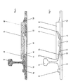
- a device for fastening rails in the form of stock rails (10) is shown, to which a sliding chair (12) is assigned in a known manner, on which a switch tongue, not shown, is slidably arranged is.
- the stock rail (10) and the sliding chair (12) start from a base plate (14) which is provided on the side of the stock rail (10) facing away from the sliding chair (12) with a stop (16) against which the rail foot (18 ) concerns.
- a hold-down device in the form of a U-shaped spring element (20) is provided, which in the region of its web (22) is held in a receptacle (24) that causes tension. is fixed, which runs in the sliding chair (12).
- the receptacle or recess (24) starts from the bottom side (26) of the sliding chair and extends obliquely upwards in the direction of the rear end (28) of the sliding chair.
- the slope formed in this way forms a clamping wedge (30) for the spring element (30).
- the sliding chair (12) projects with a front section (40), which runs between the leg ends (34) and (39) of the spring element (20), in regions over the rail foot (36).
- the area of the sliding chair (12) facing the rail (10) is beak-shaped, that is, between the area (40) running above the rail foot surface (36) and one below the rail foot and one in the direction of the
- the projection (42) of the base plate (14), which extends along the sliding chair, has a recess (44) which is delimited at the bottom by a section (46) of the sliding chair (12).
- the beak-shaped front end of the sliding chair (12) engages the portion formed by the front rail foot with the longitudinal side surface (38) and the projection (42).
- the hold-down device formed by the spring element (20) consequently runs from the recess (24) below the counter bearing (32) and (31) in order to grasp the rail foot (36) with its free ends (34) and (39). As a result, the stock rail (10) is pressed onto the base plate (14).
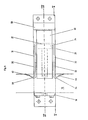
- FIGS. 4 and 5 show, the end (28) of the sliding chair (12) is supported against a projection (50) protruding from the base plate (14), which preferably has an undercut. This ensures that the sliding chair (12) is positioned precisely on the base plate (14).
- 2 includes a Deviating design, as that the rear end provided with the reference symbol (52) has a bevel (54) which comes to rest against a ramp-shaped elevation (56) of the base plate (14), so that this enables self-locking fixing.
- the sliding chair (12) is wider than the base plate (14)
- the base plate (58) shown in FIGS. 4 to 6 is wider than the sliding chair (60).
- the U-shaped spring element (20) is also fixed with the web (22) connecting the side legs (33) and (35) in the clamping receptacle (24) and lies with its free leg ends (34) and (39) on the one hand the surface (36) and on the other on the end face surfaces (38) of the rail foot (18).
- the free ends (36) and (38) are angled such that they have a section (62) and (64) parallel to the surface (36) and angled with their ends and parallel to the end face surfaces (38) .
- One of these angled ends is shown in FIG. 5 and provided with the reference number (66).
- the beak-shaped front end formed by the sections (40) and (46) delimiting the gap or slot (44), detects only the front end of the rail foot (18). This setting also ensures that the sliding chair (60) cannot be moved in an uncontrolled manner since it is prevented from being lifted by the section (46) which grips the underside of the rail foot (18).
- the base plate (58) also comprises cutouts (48) intended for the legs (33) and (35).
- the teaching according to the invention makes it possible to easily replace the sliding chair (12) or (60) with the hold-down device (20). Furthermore, it is ensured that, even if the spring force should decrease, the stock rail moves in the direction of the base plate (14) or (58) experiences directed force, since the front end (40) of the sliding chair (12) or (60) also serves as a hold-down device and prevents the stock rail (10) from tipping away.
- the surface of the sliding chair (12) or (60) can be provided with a lubricant that is hard and has emergency running properties.
- a lubricant that is hard and has emergency running properties.
- GGG autogenous spheroidal graphite cast iron
- the lubricant can be applied to the sliding chair by welding or in the plasma or flame spray process, the lubricant then preferably containing molybdenum or ternary or quaternary alloys based on Co or Ni, optionally with additives such as Mo, Cr and / or Si.
- the areas of the sliding chair that have been lubricated should be decarburized to avoid martensite formation.
Landscapes
- Engineering & Computer Science (AREA)
- Mechanical Engineering (AREA)
- Architecture (AREA)
- Civil Engineering (AREA)
- Structural Engineering (AREA)
- Chairs For Special Purposes, Such As Reclining Chairs (AREA)
- Clamps And Clips (AREA)
- Chair Legs, Seat Parts, And Backrests (AREA)
- Holders For Apparel And Elements Relating To Apparel (AREA)
- Supports Or Holders For Household Use (AREA)
- Machines For Laying And Maintaining Railways (AREA)
- Electrical Discharge Machining, Electrochemical Machining, And Combined Machining (AREA)
- Forklifts And Lifting Vehicles (AREA)
Claims (10)
caractérisé en ce que
l'éclisse (20) est un élément élastique qui se fixe dans un logement (24) de la plaque de fixation (12, 60) tournée vers la plaque d'appui (14, 58) et sur la semelle (18, 36, 38) en s'appuyant sur un contre-appui (31, 32) partant de la plaque d'appui.
caractérisé en ce que
l'éclisse (20) est en forme de U et ses extrémités de branche (34, 39) s'appuient sur la semelle (36) du rail.
caractérisé en ce que
le logement (24) est une cavité dirigée vers le côté supérieur et l'extrémité (28, 52) de la plaque de fixation de rail (12, 60) opposée au rail.
caractérisé en ce que
les extrémités libres (34, 39) des branches (33, 35) de l'éclisse (20) en forme de U, montée de manière amovible sur la plaque de fixation de rail (12, 60) sont recourbées de manière à s'appuyer à la fois sur la face supérieure de la semelle (36) du rail et sur les surfaces latérales longitudinales (38).
caractérisé en ce que
l'éclisse (20) en forme d'élément élastique est montée préalablement sur la plaque de fixation de rail (12, 60) et cet élément est fixé dans le logement (24) de préférence avec précontrainte.
caractérisé en ce que
la zone de l'ouverture de la cavité (24) éloignée du rail (10) présente une partie en saillie telle qu'un bec.
caractérisé en ce que
la zone (40, 44, 46) prise par la partie en saillie (38, 42) est en forme de bec, formée à la fois par le segment de la semelle (18) et par un segment de la plaque d'appui (14).
caractérisé en ce que
l'éclisse est le segment (40) de la plaque de fixation (12, 60) qui passe au-dessus de la semelle (36) à côté de l'élément élastique (20).
caractérisé en ce que
la plaque de fixation de rail (12) est fixée de manière autobloquante sur la plaque d'appui (14).
caractérisé en ce que
la surface supérieure de la plaque de fixation de rail (12, 60) est munie d'un moyen de glissement, dur, présentant des caractéristiques de roulement de secours et qui se termine à fleur ou pratiquement à fleur avec la surface supérieure de la plaque de glissement de l'aiguille.
Priority Applications (1)
| Application Number | Priority Date | Filing Date | Title |
|---|---|---|---|
| AT89105688T ATE78307T1 (de) | 1988-04-05 | 1989-03-31 | Vorrichtung zum befestigen von schienen. |
Applications Claiming Priority (2)
| Application Number | Priority Date | Filing Date | Title |
|---|---|---|---|
| DE3811408 | 1988-04-05 | ||
| DE3811408A DE3811408A1 (de) | 1988-04-05 | 1988-04-05 | Vorrichtung zum befestigen von schienen |
Publications (2)
| Publication Number | Publication Date |
|---|---|
| EP0336311A1 EP0336311A1 (fr) | 1989-10-11 |
| EP0336311B1 true EP0336311B1 (fr) | 1992-07-15 |
Family
ID=6351409
Family Applications (1)
| Application Number | Title | Priority Date | Filing Date |
|---|---|---|---|
| EP89105688A Expired - Lifetime EP0336311B1 (fr) | 1988-04-05 | 1989-03-31 | Dispositif de fixation de rails |
Country Status (4)
| Country | Link |
|---|---|
| EP (1) | EP0336311B1 (fr) |
| AT (1) | ATE78307T1 (fr) |
| DE (2) | DE3811408A1 (fr) |
| ES (1) | ES2034452T3 (fr) |
Cited By (1)
| Publication number | Priority date | Publication date | Assignee | Title |
|---|---|---|---|---|
| DE102004040176C5 (de) * | 2004-08-18 | 2011-01-13 | Deutsche Bahn Ag | Vorrichtung zur Befestigung einer Backenschiene auf einer gleisinneren Seite einer Zungenvorrichtung einer Weiche |
Families Citing this family (2)
| Publication number | Priority date | Publication date | Assignee | Title |
|---|---|---|---|---|
| DE19545341A1 (de) * | 1995-12-05 | 1997-06-12 | Butzbacher Weichenbau Gmbh | Gleitstuhl |
| AT509055B1 (de) | 2010-06-15 | 2011-06-15 | Vae Eisenbahnsysteme Gmbh | Vorrichtung zur befestigung einer backenschiene |
Family Cites Families (8)
| Publication number | Priority date | Publication date | Assignee | Title |
|---|---|---|---|---|
| DE1142378B (de) * | 1961-03-28 | 1963-01-17 | Kloeckner Werke Ag | Gleitstuhl fuer Zungenvorrichtungen von Weichen |
| DE1708640A1 (de) * | 1967-01-05 | 1971-05-19 | Deenik Johan Frederik Dipl Ing | Vorrichtung zur Befestigung einer Eisenbahnschiene an eine Stahl-,Beton- oder Holzschwelle und Verfahren zur Einstellung der Hoehe einer Eisenbahnschiene |
| DE2000482B1 (de) * | 1970-01-07 | 1970-12-23 | Schreck Mieves Kg | Vorrichtung zum Befestigen von Backenschienen in Weichen |
| DD112151A1 (fr) * | 1974-01-03 | 1975-03-20 | ||
| EP0113515A1 (fr) * | 1982-12-02 | 1984-07-18 | Thos. W. Ward (Railway Engineers) Ltd | Agencement de plaque de glissement pour la lame aiguille de chemin de fer |
| DE3411122A1 (de) * | 1984-03-26 | 1985-10-03 | BWG Butzbacher Weichenbau GmbH, 6308 Butzbach | Vorrichtung zum befestigen von schienen |
| DE3411133A1 (de) * | 1984-03-26 | 1985-10-03 | BWG Butzbacher Weichenbau GmbH, 6308 Butzbach | Vorrichtung zum befestigen von schienen |
| DE3709126A1 (de) * | 1987-03-23 | 1988-10-13 | Butzbacher Weichenbau Gmbh | Miteinander wechselwirkende gleisteile |
-
1988
- 1988-04-05 DE DE3811408A patent/DE3811408A1/de active Granted
-
1989
- 1989-03-31 AT AT89105688T patent/ATE78307T1/de not_active IP Right Cessation
- 1989-03-31 DE DE8989105688T patent/DE58901827D1/de not_active Expired - Lifetime
- 1989-03-31 EP EP89105688A patent/EP0336311B1/fr not_active Expired - Lifetime
- 1989-03-31 ES ES198989105688T patent/ES2034452T3/es not_active Expired - Lifetime
Cited By (1)
| Publication number | Priority date | Publication date | Assignee | Title |
|---|---|---|---|---|
| DE102004040176C5 (de) * | 2004-08-18 | 2011-01-13 | Deutsche Bahn Ag | Vorrichtung zur Befestigung einer Backenschiene auf einer gleisinneren Seite einer Zungenvorrichtung einer Weiche |
Also Published As
| Publication number | Publication date |
|---|---|
| EP0336311A1 (fr) | 1989-10-11 |
| DE58901827D1 (de) | 1992-08-20 |
| ES2034452T3 (es) | 1993-04-01 |
| DE3811408C2 (fr) | 1990-02-22 |
| ATE78307T1 (de) | 1992-08-15 |
| DE3811408A1 (de) | 1989-10-26 |
Similar Documents
| Publication | Publication Date | Title |
|---|---|---|
| AT405657B (de) | Vorrichtung zum festlegen von radlenkern | |
| EP0780515B1 (fr) | Dispositif pour maintenir en place un rail | |
| EP0336311B1 (fr) | Dispositif de fixation de rails | |
| DE2921826C2 (de) | Befestigungsvorrichtung für Schienen und Werkzeug zur Handhabung derselben | |
| EP0343149B1 (fr) | Dispositif pour fixer les contre-rails dans les aiguillages | |
| EP0305592B1 (fr) | Dispositif de fixation de rails | |
| AT391274B (de) | Skibindung | |
| AT402747B (de) | Vorrichtung zum befestigen von backenschienen in weichen | |
| DE3230612A1 (de) | Vorrichtung zum befestigen von backenschienen oder fahrschienen in weichen | |
| DE2409373B2 (de) | Vorrichtung zur befestigung von backenschienen in weichen | |
| DE4341586C2 (de) | Schutzblech für ein Fahrrad | |
| DE19507376C2 (de) | Verbindung zwischen einer Zunge und einer Anschlußschiene | |
| EP0393585B1 (fr) | Dispositif de fixation d'une chaussure sur une pédale de bicyclette | |
| EP0330238A2 (fr) | Plaque d'attache pour rails telle que coussinet de glissement | |
| DE2729357C3 (de) | Basisplatte für Schienenbefestigungsklammer | |
| EP0778372B1 (fr) | Coussinet de glissement | |
| DE2444286B1 (de) | Befestigungsvorrichtung fuer eine Raeumleiste an einer Schneepflugschar | |
| EP0156350B1 (fr) | Dispositif pour la fixation de rails | |
| WO1994021859A1 (fr) | Agencement de rails | |
| DE4309515A1 (de) | Schienenanordnung | |
| DE2838915C2 (de) | Tisch zum Umbau von Vorsatzhandkreissägen und Motorhandkreissägen zu einer stationären Tischkreissäge | |
| DE3105878A1 (de) | Vorrichtung zum verbinden von zwei bauteilen in vorbestimmtem abstand | |
| EP0456048B1 (fr) | Tige de plaquettes pour monture de lunettes | |
| DE2806303C2 (de) | Vorrichtung zum Befestigen von Schienen auf Schwellen, insbesondere aus Hartholz, Beton oder Eisen | |
| EP0711191A1 (fr) | Fixation de ski |
Legal Events
| Date | Code | Title | Description |
|---|---|---|---|
| PUAI | Public reference made under article 153(3) epc to a published international application that has entered the european phase |
Free format text: ORIGINAL CODE: 0009012 |
|
| AK | Designated contracting states |
Kind code of ref document: A1 Designated state(s): AT BE CH DE ES FR GB GR IT LI LU NL SE |
|
| 17P | Request for examination filed |
Effective date: 19890920 |
|
| RBV | Designated contracting states (corrected) |
Designated state(s): AT BE CH DE ES FR GB IT LI LU NL SE |
|
| 17Q | First examination report despatched |
Effective date: 19900910 |
|
| GRAA | (expected) grant |
Free format text: ORIGINAL CODE: 0009210 |
|
| AK | Designated contracting states |
Kind code of ref document: B1 Designated state(s): AT BE CH DE ES FR GB IT LI LU NL SE |
|
| REF | Corresponds to: |
Ref document number: 78307 Country of ref document: AT Date of ref document: 19920815 Kind code of ref document: T |
|
| REF | Corresponds to: |
Ref document number: 58901827 Country of ref document: DE Date of ref document: 19920820 |
|
| ITF | It: translation for a ep patent filed | ||
| ET | Fr: translation filed | ||
| GBT | Gb: translation of ep patent filed (gb section 77(6)(a)/1977) | ||
| REG | Reference to a national code |
Ref country code: ES Ref legal event code: FG2A Ref document number: 2034452 Country of ref document: ES Kind code of ref document: T3 |
|
| PLBE | No opposition filed within time limit |
Free format text: ORIGINAL CODE: 0009261 |
|
| STAA | Information on the status of an ep patent application or granted ep patent |
Free format text: STATUS: NO OPPOSITION FILED WITHIN TIME LIMIT |
|
| 26N | No opposition filed | ||
| EPTA | Lu: last paid annual fee | ||
| EAL | Se: european patent in force in sweden |
Ref document number: 89105688.9 |
|
| PGFP | Annual fee paid to national office [announced via postgrant information from national office to epo] |
Ref country code: GB Payment date: 19950321 Year of fee payment: 7 |
|
| PGFP | Annual fee paid to national office [announced via postgrant information from national office to epo] |
Ref country code: BE Payment date: 19950322 Year of fee payment: 7 |
|
| PG25 | Lapsed in a contracting state [announced via postgrant information from national office to epo] |
Ref country code: GB Effective date: 19960331 Ref country code: BE Effective date: 19960331 |
|
| BERE | Be: lapsed |
Owner name: BWG BUTZBACHER WEICHENBAU G.M.B.H. Effective date: 19960331 |
|
| GBPC | Gb: european patent ceased through non-payment of renewal fee |
Effective date: 19960331 |
|
| PGFP | Annual fee paid to national office [announced via postgrant information from national office to epo] |
Ref country code: CH Payment date: 20030218 Year of fee payment: 15 |
|
| PGFP | Annual fee paid to national office [announced via postgrant information from national office to epo] |
Ref country code: LU Payment date: 20030227 Year of fee payment: 15 |
|
| PGFP | Annual fee paid to national office [announced via postgrant information from national office to epo] |
Ref country code: NL Payment date: 20030228 Year of fee payment: 15 |
|
| PGFP | Annual fee paid to national office [announced via postgrant information from national office to epo] |
Ref country code: SE Payment date: 20030304 Year of fee payment: 15 Ref country code: AT Payment date: 20030304 Year of fee payment: 15 |
|
| PGFP | Annual fee paid to national office [announced via postgrant information from national office to epo] |
Ref country code: DE Payment date: 20030311 Year of fee payment: 15 |
|
| PGFP | Annual fee paid to national office [announced via postgrant information from national office to epo] |
Ref country code: FR Payment date: 20030314 Year of fee payment: 15 |
|
| PGFP | Annual fee paid to national office [announced via postgrant information from national office to epo] |
Ref country code: ES Payment date: 20030320 Year of fee payment: 15 |
|
| PG25 | Lapsed in a contracting state [announced via postgrant information from national office to epo] |
Ref country code: LU Free format text: LAPSE BECAUSE OF NON-PAYMENT OF DUE FEES Effective date: 20040331 Ref country code: LI Free format text: LAPSE BECAUSE OF NON-PAYMENT OF DUE FEES Effective date: 20040331 Ref country code: CH Free format text: LAPSE BECAUSE OF NON-PAYMENT OF DUE FEES Effective date: 20040331 Ref country code: AT Free format text: LAPSE BECAUSE OF NON-PAYMENT OF DUE FEES Effective date: 20040331 |
|
| PG25 | Lapsed in a contracting state [announced via postgrant information from national office to epo] |
Ref country code: SE Free format text: LAPSE BECAUSE OF NON-PAYMENT OF DUE FEES Effective date: 20040401 Ref country code: ES Free format text: LAPSE BECAUSE OF NON-PAYMENT OF DUE FEES Effective date: 20040401 |
|
| PG25 | Lapsed in a contracting state [announced via postgrant information from national office to epo] |
Ref country code: NL Free format text: LAPSE BECAUSE OF NON-PAYMENT OF DUE FEES Effective date: 20041001 Ref country code: DE Free format text: LAPSE BECAUSE OF NON-PAYMENT OF DUE FEES Effective date: 20041001 |
|
| REG | Reference to a national code |
Ref country code: CH Ref legal event code: PL |
|
| EUG | Se: european patent has lapsed | ||
| PG25 | Lapsed in a contracting state [announced via postgrant information from national office to epo] |
Ref country code: FR Free format text: LAPSE BECAUSE OF NON-PAYMENT OF DUE FEES Effective date: 20041130 |
|
| NLV4 | Nl: lapsed or anulled due to non-payment of the annual fee |
Effective date: 20041001 |
|
| REG | Reference to a national code |
Ref country code: FR Ref legal event code: ST |
|
| PG25 | Lapsed in a contracting state [announced via postgrant information from national office to epo] |
Ref country code: IT Free format text: LAPSE BECAUSE OF NON-PAYMENT OF DUE FEES;WARNING: LAPSES OF ITALIAN PATENTS WITH EFFECTIVE DATE BEFORE 2007 MAY HAVE OCCURRED AT ANY TIME BEFORE 2007. THE CORRECT EFFECTIVE DATE MAY BE DIFFERENT FROM THE ONE RECORDED. Effective date: 20050331 |
|
| REG | Reference to a national code |
Ref country code: ES Ref legal event code: FD2A Effective date: 20040401 |