EP0336311B1 - Rail fastening assembly - Google Patents
Rail fastening assembly Download PDFInfo
- Publication number
- EP0336311B1 EP0336311B1 EP89105688A EP89105688A EP0336311B1 EP 0336311 B1 EP0336311 B1 EP 0336311B1 EP 89105688 A EP89105688 A EP 89105688A EP 89105688 A EP89105688 A EP 89105688A EP 0336311 B1 EP0336311 B1 EP 0336311B1
- Authority
- EP
- European Patent Office
- Prior art keywords
- rail
- base plate
- spring element
- fixing plate
- foot
- Prior art date
- Legal status (The legal status is an assumption and is not a legal conclusion. Google has not performed a legal analysis and makes no representation as to the accuracy of the status listed.)
- Expired - Lifetime
Links
Images


Classifications
-
- E—FIXED CONSTRUCTIONS
- E01—CONSTRUCTION OF ROADS, RAILWAYS, OR BRIDGES
- E01B—PERMANENT WAY; PERMANENT-WAY TOOLS; MACHINES FOR MAKING RAILWAYS OF ALL KINDS
- E01B7/00—Switches; Crossings
- E01B7/22—Special sleepers for switches or crossings; Fastening means therefor
-
- E—FIXED CONSTRUCTIONS
- E01—CONSTRUCTION OF ROADS, RAILWAYS, OR BRIDGES
- E01B—PERMANENT WAY; PERMANENT-WAY TOOLS; MACHINES FOR MAKING RAILWAYS OF ALL KINDS
- E01B9/00—Fastening rails on sleepers, or the like
- E01B9/38—Indirect fastening of rails by using tie-plates or chairs; Fastening of rails on the tie-plates or in the chairs
- E01B9/44—Fastening the rail on the tie-plate
- E01B9/46—Fastening the rail on the tie-plate by clamps
- E01B9/48—Fastening the rail on the tie-plate by clamps by resilient steel clips
- E01B9/486—Fastening the rail on the tie-plate by clamps by resilient steel clips the clip being a shaped plate
Definitions
- the invention relates to a device for fastening a rail, preferably in the form of a stock rail or travel rail with an associated wheel handlebar stand, in the area of a switch and / or crossing, comprising a base plate for the rail, a sliding chair or a wheel handlebar footplate, which or releasably the support plate is arranged and acts as a rail fastening plate, and a hold-down device, which starts from the support plate, for holding down the rail, the rail fastening plate having a beak-shaped region facing the rail foot, which interacts with at least one projection formed by a section of the rail foot.
- a device for attaching stock rails in switches is e.g. can be found in DE-B 20 00 482.
- the rail mounting plate ie the sliding chair, is firmly connected to the base plate and the rail foot is held down by a spring element extending from the sliding chair. There is no direct interaction between the sliding chair and the rail foot, which causes the holding down.
- a disadvantage of corresponding devices is that the entire unit consisting of the base plate and sliding chair must be replaced if the rail fastening plate wears.
- EP-A 0 113 515 describes a device for fastening a rail in the area of switches with a two-part sliding chair, from which a U-shaped spring element for holding down the rail starts.
- a device for fastening rails with a detachably arranged rail fastening plate can be found in EP-A 0 156 349.
- the end facing the rail foot is beak-shaped in order to grip a projection formed by the rail foot and the base plate.
- the rail mounting plate itself is pressed against the rail base using a clamping element such as a wedge.
- the object of the present invention is to design a device of the type mentioned in the introduction EP-A 0 156 349 in such a way that a structurally simple means ensures that the rail foot is held down securely, with neither retightening of fastening elements being necessary, nor in the event of wear Rail mounting plate this must be replaced together with the base plate.
- the installation or interchangeability of the rail mounting plate should be improved or facilitated compared to known designs.
- the holding-down device is a spring element which can be fixed in a receptacle of the rail fastening plate facing the base plate and on the rail foot and can be supported on a counter bearing extending from the base plate.
- the spring element is preferably U-shaped and releasably secured in the receptacle, the ends of the legs being supported on the rail foot.
- the ends of the legs are designed so that on the one hand they produce a force running in the vertical direction and on the other hand a horizontally directed force on the rail foot, by means of which the rail foot is pressed against the base plate and a stop element which is in relation to the rail foot is arranged on the side of the base plate opposite the rail fastening plate.
- the ends are of an angular shape so that they rest on the top of the rail foot and on the side longitudinal surfaces.
- the legs of the spring element are curved such that the ends and the web connecting the legs run higher than the contact area of the counter bearing.
- the receptacle is preferably a recess running in the direction of the upper side and the end of the rail fastening plate facing away from the rail, through which the web area of the spring element is consequently guided away from the lower plate, as a result of which the spring element itself is subjected to the required prestress.
- the counter bearing the underside of which is preferably aligned with that of the rail fastening plate, runs laterally from the latter, but can also protrude into a correspondingly designed recess in the rail fastening plate.
- the spring element together with the rail fastening plate form a preassembled unit, the spring element being able to be fastened in the receptacle by self-prestressing.
- the mounting of the rail fastening plate that is to say the insertion of the spring element into the receptacle, can be facilitated in that the region of the opening of the recess remote from the rail has a projection such as a nose.
- the projection consequently forms an auxiliary lug in order to thread the spring element into the clamping recess.
- the teaching according to the invention results, inter alia, in the additional advantage that the rail fastening plate itself can press onto the rail foot without additional measures being required. This ensures that the rail is securely attached even if the spring force should decrease. The rail cannot tip over.
- an additional one is carried out Force input onto the sliding chair and thus onto the rail foot of the bottom rail, so that tilting of the stock rail is also avoided.
- the rail mounting plate itself can preferably be arranged on the base plate in a self-locking manner. This can be done structurally in that the end of the rail fastening plate facing away from the rail foot comes to rest against a ramp-shaped projection or an undercut which cannot be overcome due to the force caused by the spring element.
- a stop can be provided at a distance from its rear end, against which a tool can be supported, which e.g. engages in the recess in the end region of the rail fastening plate and thus enables the rail fastening plate to be lifted out.
- the rail fastening plate is provided with a hard lubricant which has emergency running properties.
- the rail mounting plate or the lubricant can be made of rust-free austenitic cast iron, such as spheroidal graphite (GGG), which can have Ni and Cr components.
- the Ni content can be 18 to 22% and the Cr content 1.0 to 2.5% of the GGG lubricant.
- the areas provided with the lubricant can also be decarburized at the edge.
- a device for fastening rails in the form of stock rails (10) is shown, to which a sliding chair (12) is assigned in a known manner, on which a switch tongue, not shown, is slidably arranged is.
- the stock rail (10) and the sliding chair (12) start from a base plate (14) which is provided on the side of the stock rail (10) facing away from the sliding chair (12) with a stop (16) against which the rail foot (18 ) concerns.
- a hold-down device in the form of a U-shaped spring element (20) is provided, which in the region of its web (22) is held in a receptacle (24) that causes tension. is fixed, which runs in the sliding chair (12).
- the receptacle or recess (24) starts from the bottom side (26) of the sliding chair and extends obliquely upwards in the direction of the rear end (28) of the sliding chair.
- the slope formed in this way forms a clamping wedge (30) for the spring element (30).
- the sliding chair (12) projects with a front section (40), which runs between the leg ends (34) and (39) of the spring element (20), in regions over the rail foot (36).
- the area of the sliding chair (12) facing the rail (10) is beak-shaped, that is, between the area (40) running above the rail foot surface (36) and one below the rail foot and one in the direction of the
- the projection (42) of the base plate (14), which extends along the sliding chair, has a recess (44) which is delimited at the bottom by a section (46) of the sliding chair (12).
- the beak-shaped front end of the sliding chair (12) engages the portion formed by the front rail foot with the longitudinal side surface (38) and the projection (42).
- the hold-down device formed by the spring element (20) consequently runs from the recess (24) below the counter bearing (32) and (31) in order to grasp the rail foot (36) with its free ends (34) and (39). As a result, the stock rail (10) is pressed onto the base plate (14).
- FIGS. 4 and 5 show, the end (28) of the sliding chair (12) is supported against a projection (50) protruding from the base plate (14), which preferably has an undercut. This ensures that the sliding chair (12) is positioned precisely on the base plate (14).
- 2 includes a Deviating design, as that the rear end provided with the reference symbol (52) has a bevel (54) which comes to rest against a ramp-shaped elevation (56) of the base plate (14), so that this enables self-locking fixing.
- the sliding chair (12) is wider than the base plate (14)
- the base plate (58) shown in FIGS. 4 to 6 is wider than the sliding chair (60).
- the U-shaped spring element (20) is also fixed with the web (22) connecting the side legs (33) and (35) in the clamping receptacle (24) and lies with its free leg ends (34) and (39) on the one hand the surface (36) and on the other on the end face surfaces (38) of the rail foot (18).
- the free ends (36) and (38) are angled such that they have a section (62) and (64) parallel to the surface (36) and angled with their ends and parallel to the end face surfaces (38) .
- One of these angled ends is shown in FIG. 5 and provided with the reference number (66).
- the beak-shaped front end formed by the sections (40) and (46) delimiting the gap or slot (44), detects only the front end of the rail foot (18). This setting also ensures that the sliding chair (60) cannot be moved in an uncontrolled manner since it is prevented from being lifted by the section (46) which grips the underside of the rail foot (18).
- the base plate (58) also comprises cutouts (48) intended for the legs (33) and (35).
- the teaching according to the invention makes it possible to easily replace the sliding chair (12) or (60) with the hold-down device (20). Furthermore, it is ensured that, even if the spring force should decrease, the stock rail moves in the direction of the base plate (14) or (58) experiences directed force, since the front end (40) of the sliding chair (12) or (60) also serves as a hold-down device and prevents the stock rail (10) from tipping away.
- the surface of the sliding chair (12) or (60) can be provided with a lubricant that is hard and has emergency running properties.
- a lubricant that is hard and has emergency running properties.
- GGG autogenous spheroidal graphite cast iron
- the lubricant can be applied to the sliding chair by welding or in the plasma or flame spray process, the lubricant then preferably containing molybdenum or ternary or quaternary alloys based on Co or Ni, optionally with additives such as Mo, Cr and / or Si.
- the areas of the sliding chair that have been lubricated should be decarburized to avoid martensite formation.
Abstract
Description
Die Erfindung bezieht sich auf eine Vorrichtung zum Befestigen einer Schiene, vorzugsweise in Form einer Backenschiene oder Fahrschiene mit zugeordnetem Radlenkerständer, im Bereich einer Weiche und/oder Kreuzung umfassend eine Unterlageplatte für die Schiene, einen Gleitstuhl oder eine Radlenkerfußplatte, der bzw. die lösbar auf der Unterlageplatte angeordnet ist und als Schienenbefestigungsplatte wirkt, und einen von der Unterlageplatte ausgehenden Niederhalter zum Niederhalten der Schiene, wobei die Schienenbefestigungsplatte einen dem Schienenfuß zugewandten schnabelförmig ausgebildeten Bereich aufweist, der mit zumindest einem von einem Abschnitt des Schienenfußes gebildeten Vorsprung wechselwirkt.The invention relates to a device for fastening a rail, preferably in the form of a stock rail or travel rail with an associated wheel handlebar stand, in the area of a switch and / or crossing, comprising a base plate for the rail, a sliding chair or a wheel handlebar footplate, which or releasably the support plate is arranged and acts as a rail fastening plate, and a hold-down device, which starts from the support plate, for holding down the rail, the rail fastening plate having a beak-shaped region facing the rail foot, which interacts with at least one projection formed by a section of the rail foot.
Eine Vorrichtung zum Befestigen von Backenschienen in Weichen ist z.B. der DE-B 20 00 482 zu entnehmen. Dabei ist die Schienenbefestigungsplatte, also der Gleitstuhl fest mit der Unterlageplatte verbunden und der Schienenfuß über ein von dem Gleitstuhl ausgehendes Federelement niedergehalten. Zwischen dem Gleitstuhl und dem Schienenfuß erfolgt keine unmittelbare Wechselwirkung, die das Niederhalten hervorruft. Ein Nachteil entsprechender Vorrichtungen ist dahin zu sehen, daß bei einem Verschleiß der Schienenbefestigungsplatte die gesamte Einheit bestehend aus Unterlageplatte und Gleitstuhl ausgetauscht werden muß.A device for attaching stock rails in switches is e.g. can be found in DE-B 20 00 482. The rail mounting plate, ie the sliding chair, is firmly connected to the base plate and the rail foot is held down by a spring element extending from the sliding chair. There is no direct interaction between the sliding chair and the rail foot, which causes the holding down. A disadvantage of corresponding devices is that the entire unit consisting of the base plate and sliding chair must be replaced if the rail fastening plate wears.
In der EP-A 0 113 515 ist eine Vorrichtung zum Befestigen einer Schiene im Bereich von Weichen mit einem zweiteiligen Gleitstuhl beschrieben, von dem ein U-förmiges Federelement zum Niederhalten der Schiene ausgeht. Ein sich mit einem Abschnitt auf dem Fuß der Schiene abstützendes erstes Teil des Gleitstuhls geht lösbar von einem zweiten Teil aus, das fortwährend mit einer Unterlage verbunden ist, auf der der Gleitstuhl angeordnet ist.EP-A 0 113 515 describes a device for fastening a rail in the area of switches with a two-part sliding chair, from which a U-shaped spring element for holding down the rail starts. A first part of the sliding chair, which is supported with a section on the foot of the rail, releasably starts from a second part which is continuously connected to a base on which the sliding chair is arranged.
Eine Vorrichtung zum Befestigen von Schienen mit lösbar angeordneter Schienenbefestigungsplatte ist der EP-A 0 156 349 zu entnehmen. Das dem Schienenfuß zugewandte Ende ist schnabelförmig ausgebildet, um einen von Schienenfuß und Unterlageplatte gebildeten Vorsprung zu erfassen. Die Schienenbefestigungsplatte selbst wird über ein Spannelement wie Keil gegen den Schienenfuß gedrückt.A device for fastening rails with a detachably arranged rail fastening plate can be found in EP-A 0 156 349. The end facing the rail foot is beak-shaped in order to grip a projection formed by the rail foot and the base plate. The rail mounting plate itself is pressed against the rail base using a clamping element such as a wedge.
Aufgabe der vorliegenden Erfindung ist es, eine Vorrichtung der eingangs genannten Art EP-A 0 156 349 so auszubilden, daß mit konstruktiv einfachen Mitteln ein sicheres Niederhalten des Schienenfußes gewährleistet ist, wobei weder ein Nachziehen von Befestigungselementen erforderlich sein soll, noch bei einem Verschleiß der Schienenbefestigungsplatte diese zusammen mit der Unterlageplatte auszutauschen ist. Dabei soll der Einbau bzw. die Auswechselbarkeit der Schienenbefestigungsplatte gegenüber bekannten Konstruktionen verbessert bzw. erleichtert werden.The object of the present invention is to design a device of the type mentioned in the introduction EP-A 0 156 349 in such a way that a structurally simple means ensures that the rail foot is held down securely, with neither retightening of fastening elements being necessary, nor in the event of wear Rail mounting plate this must be replaced together with the base plate. The installation or interchangeability of the rail mounting plate should be improved or facilitated compared to known designs.
Die Aufgabe wird erfindungsgemäß dadurch gelöst, daß der Niederhalter ein Federelement ist, das in einer der Unterlageplatte zugewandten Aufnahme der Schienenbefestigungsplatte und auf dem Schienenfuß festlegbar und an einem von der Unterlageplatte ausgehenden Gegenlager abstützbar ist. Dabei ist das Federelement vorzugsweise U-förmig ausgebildet und lösbar in der Aufnahme festgelegt, wobei die Enden der Schenkel auf dem Schienenfuß abstützbar sind. Vorzugsweise sind die Enden der Schenkel so ausgebildet, daß sie zum einen eine in vertikaler Richtung verlaufende Kraft und zum anderen eine horizontal gerichtete Kraft auf den Schienenfuß hervorruft, durch die der Schienenfuß gegen die Unterlageplatte und ein Anschlagelement gedrückt wird, das in bezug auf den Schienenfuß auf der der Schienenbefestigungsplatte gegenüberliegenden Seite der Unterlageplatte angeordnet ist. Mit anderen Worten sind die Enden winkelförmig ausgebildet, um so zum einen auf der Oberseite des Schienenfußes und zum anderen an den Seitenlängsflächen anzuliegen. Durch die erfindungsgemäße Lehre verlaufen die Schenkel des Federelemnts derart gebogen, daß die Enden und der die Schenkel verbindende Steg gegenüber dem Berührungsbereich der Gegenlager höher verlaufen.The object is achieved in that the holding-down device is a spring element which can be fixed in a receptacle of the rail fastening plate facing the base plate and on the rail foot and can be supported on a counter bearing extending from the base plate. The spring element is preferably U-shaped and releasably secured in the receptacle, the ends of the legs being supported on the rail foot. Preferably, the ends of the legs are designed so that on the one hand they produce a force running in the vertical direction and on the other hand a horizontally directed force on the rail foot, by means of which the rail foot is pressed against the base plate and a stop element which is in relation to the rail foot is arranged on the side of the base plate opposite the rail fastening plate. In other words, the ends are of an angular shape so that they rest on the top of the rail foot and on the side longitudinal surfaces. Through the teaching of the invention the legs of the spring element are curved such that the ends and the web connecting the legs run higher than the contact area of the counter bearing.
Bevorzugterweise ist die Aufnahme eine in Richtung der Oberseite und des der Schiene abgewandten Endes der Schienenbefestigungsplatte verlaufende Aussparung, durch die folglich der Stegbereich des Federelementes von der Unterplatte weg geführt wird, wodurch das Federelement selbst die erforderliche Vorspannung erfährt. Das Gegenlager, dessen Unterseite vorzugsweise mit der der Schienenbefestigungsplatte fluchtet, verläuft seitlich von dieser, kann jedoch auch in einer entsprechend ausgebildeten Aussparung der Schienenbefestigungsplatte hineinragen.The receptacle is preferably a recess running in the direction of the upper side and the end of the rail fastening plate facing away from the rail, through which the web area of the spring element is consequently guided away from the lower plate, as a result of which the spring element itself is subjected to the required prestress. The counter bearing, the underside of which is preferably aligned with that of the rail fastening plate, runs laterally from the latter, but can also protrude into a correspondingly designed recess in the rail fastening plate.
Nach einer weiteren hervorzuhebenden Ausgestaltung der Erfindung bilden das Federelement zusammen mit der Schienenbefestigungsplatte eine vormontierte Einheit, wobei das Federelement durch Eigenvorspannung in der Aufnahme befestigbar ist.According to a further embodiment of the invention which is to be emphasized, the spring element together with the rail fastening plate form a preassembled unit, the spring element being able to be fastened in the receptacle by self-prestressing.
Sofern eine entsprechende Einheit nicht vorliegt, kann das Montieren der Schienenbefestigungsplatte, also das Einführen des Federelementes in die Aufnahme dadurch erleichtert werden, daß der der Schiene fernliegende Bereich der Öffnung der Ausnehmung einen Vorsprung wie Nase aufweist. Der Vorsprung bildet demzufolge eine Hilfsnase, um das Federelement in die Spannausnehmung einzufädeln.If a corresponding unit is not present, the mounting of the rail fastening plate, that is to say the insertion of the spring element into the receptacle, can be facilitated in that the region of the opening of the recess remote from the rail has a projection such as a nose. The projection consequently forms an auxiliary lug in order to thread the spring element into the clamping recess.
Durch die erfindungsgemäße Lehre ergibt sich u.a. der zusätzliche Vorteil, daß die Schienenbefestigungsplatte selbst auf den Schienenfuß drücken kann, ohne daß zusätzliche Maßnahmen erforderlich sind. Hierdurch bedingt ist auch dann ein sicheres Festlegen der Schiene gewährleistet, wenn die Federkraft nachlassen sollte. Ein Kippen der Schiene ist ausgeschlossen. Beim Befahren des auf der Schienenbefestigungsplatte abgestützten Schienenteils wie Zunge erfolgt eine zusätzliche Krafteinlenkung auf den Gleitstuhl und damit auf den Schienenfuß der Bodenschiene, so daß ebenfalls ein Wegkippen der Backenschiene vermieden wird.The teaching according to the invention results, inter alia, in the additional advantage that the rail fastening plate itself can press onto the rail foot without additional measures being required. This ensures that the rail is securely attached even if the spring force should decrease. The rail cannot tip over. When driving on the rail part, such as the tongue, supported on the rail fastening plate, an additional one is carried out Force input onto the sliding chair and thus onto the rail foot of the bottom rail, so that tilting of the stock rail is also avoided.
Die Schienenbefestigungsplatte selbst kann vorzugsweise selbsthemmend auf der Unterlageplatte angeordnet sein. Dies kann konstruktiv dadurch erfolgen, daß das dem Schienenfuß abgewandte Ende der Schienenbefestigungsplatte gegen einen rampenförmigen oder eine Hinterschneidung aufweisenden Vorsprung zum Anliegen kommt, der aufgrund der von dem Federelement hervorgerufen Kraft nicht überwindbar ist.The rail mounting plate itself can preferably be arranged on the base plate in a self-locking manner. This can be done structurally in that the end of the rail fastening plate facing away from the rail foot comes to rest against a ramp-shaped projection or an undercut which cannot be overcome due to the force caused by the spring element.
Um ein leichtes Entfernen einer Schienenbefestigungsplatte zu ermöglichen, kann im Abstand zu ihrem hinteren Ende ein Anschlag vorgesehen sein, gegen den ein Werkzeug abstützbar ist, der eine z.B. im Endbereich der Schienenbefestigungsplatte vorhandenen Aussparung eingreift und somit ein Herausheben der Schienenbefestigungsplatte ermöglicht.In order to enable an easy removal of a rail fastening plate, a stop can be provided at a distance from its rear end, against which a tool can be supported, which e.g. engages in the recess in the end region of the rail fastening plate and thus enables the rail fastening plate to be lifted out.
Schließlich kann vorgesehen sein, daß die Schienenbefestigungsplatte mit einem harten, Notlaufeigenschaften aufweisendem Gleitmittel versehen ist. Ferner kann die Schienenbefestigungsplatte oder das Gleitmittel aus nichtrostendem austenitischem Gußeisen wie Kugelgraphit (GGG), das Ni- und Cr-Anteile aufweisen kann, bestehen. Der Ni- Anteil kann dabei 18 bis 22 % und der Cr-Anteil 1,0 bis 2,5 % des GGG-Gleitmittels sein. Auch können die mit dem Gleitmittel versehenen Bereiche randentkohlt sein.Finally, it can be provided that the rail fastening plate is provided with a hard lubricant which has emergency running properties. Furthermore, the rail mounting plate or the lubricant can be made of rust-free austenitic cast iron, such as spheroidal graphite (GGG), which can have Ni and Cr components. The Ni content can be 18 to 22% and the Cr content 1.0 to 2.5% of the GGG lubricant. The areas provided with the lubricant can also be decarburized at the edge.
Weitere Einzelheiten, Vorteile und Merkmale der Erfindung ergeben sich nicht nur aus den Ansprüchen, den diesen zu entnehmenden Merkmalen -für sich und/oder in Kombination-, sondern auch aus der nachfolgenden Beschreibung eines in der Zeichnung dargestellten bevorzugten Ausführungsbeispiels. Es zeigen:
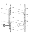
- Fig. 1 einen Schnitt entlang der Linie I-I in Fig. 3,
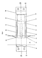
- Fig. 2 einen Schnitt entlang der Linie II-II in Fig. 3,
- Fig. 3 eine Draufsicht auf eine Vorrichtung zum Befestigen von Schienen,
- Fig. 4 einen Schnitt entlang der Linie IV-IV in Fig. 6,
- Fig. 5 in etwa entlang der Linie IV-IV in Fig. 6 und
- Fig. 6 eine zweite Ausführungsform einer Vorrichtung zum Befestigen von Schienen.
- 1 shows a section along the line II in FIG. 3,
- 2 shows a section along the line II-II in FIG. 3,
- 3 is a plan view of a device for fastening rails,
- 4 shows a section along the line IV-IV in FIG. 6,
- Fig. 5 approximately along the line IV-IV in Fig. 6 and
- Fig. 6 shows a second embodiment of a device for fastening rails.
In den Figuren, in denen gleiche Elemente mit gleichen Bezugszeichen versehen sind, ist eine Vorrichtung zur Befestigung von Schienen in Form von Backenschienen (10) dargestellt, denen in bekannter Weise ein Gleitstuhl (12) zugeordnet ist, auf dem eine nicht dargestellte Weichenzunge gleitend angeordnet ist. Die Backenschiene (10) sowie der Gleitstuhl (12) gehen von einer Unterlageplatte (14) aus, die auf der dem Gleitstuhl (12) abgewandten Seite der Backenschiene (10) mit einem Anschlag (16) versehen ist, gegen den der Schienenfuß (18) zum Anliegen kommt.In the figures, in which the same elements are provided with the same reference numerals, a device for fastening rails in the form of stock rails (10) is shown, to which a sliding chair (12) is assigned in a known manner, on which a switch tongue, not shown, is slidably arranged is. The stock rail (10) and the sliding chair (12) start from a base plate (14) which is provided on the side of the stock rail (10) facing away from the sliding chair (12) with a stop (16) against which the rail foot (18 ) concerns.
Damit der Schienenfuß (18) fest auf der Unterlageplatte (14) zu liegen kommt, ist ein Niederhalter in Form eines U-förmig ausgebildeten Federelementes (20) vorgesehen, das im Bereich seines Stegs (22) in einer eine Spannung hervorrufende Aufnahme (24) festgelegt ist, die im Gleitstuhl (12) verläuft. Dabei geht die Aufnahme bzw. Ausnehmung (24) von der Bodenseite (26) des Gleitstuhls aus und erstreckt sich schräg nach oben in Richtung des hinteren Endes (28) des Gleitstuhls. Die so gebildete Schräge bildet einen Spannkeil (30) für das Federelement (30).So that the rail foot (18) comes to rest firmly on the base plate (14), a hold-down device in the form of a U-shaped spring element (20) is provided, which in the region of its web (22) is held in a receptacle (24) that causes tension. is fixed, which runs in the sliding chair (12). The receptacle or recess (24) starts from the bottom side (26) of the sliding chair and extends obliquely upwards in the direction of the rear end (28) of the sliding chair. The slope formed in this way forms a clamping wedge (30) for the spring element (30).
Von der Unterlageplatte (14) gehen als Gegenlager (32) und (31) ausgebildete Vorsprünge aus, unter denen das Federelement (20) verläuft. Die vorderen Enden (34) und (39) des Federelementes (20) liegen dann auf der Oberseite (36) und gegebenenfalls auch an den Längsseitenflächen (38) des Schienenfusses (18) an. Die Form der Schenkel (33) und (35) des Federelements (20) bildet folglich einen Bogen, dessen tiefster Punkt durch die Gegenlager (31) (32) gebildet wird.From the base plate (14) protrusions formed as counter bearings (32) and (31), under which the spring element (20) runs. The front ends (34) and (39) of the spring element (20) then rest on the upper side (36) and optionally also on the longitudinal side surfaces (38) of the rail foot (18). The shape of the legs (33) and (35) of the spring element (20) consequently forms an arc, the lowest point of which is formed by the counter bearing (31) (32).
Ferner ragt der Gleitstuhl (12) mit einem vorderen Abschnitt (40), der zwischen den Schenkelenden (34) und (39) des Federelementes (20) verläuft, bereichsweise über den Schienenfuß (36).Furthermore, the sliding chair (12) projects with a front section (40), which runs between the leg ends (34) and (39) of the spring element (20), in regions over the rail foot (36).
Im Ausführungsbeispiel der Fig. 1 bis 3 ist der der Schiene (10) zugewandte Bereich des Gleitstuhls (12) schnabelförmig ausgebildet, d.h., zwischen dem oberhalb der Schienenfußfläche (36) verlaufende Bereich (40) und einem unterhalb des Schienenfusses und einem in Richtung des Gleitstuhls verlaufenden Vorsprung (42) der Unterlageplatte (14) verläuft eine Aussparung (44), die bodenseitig von einem Abschnitt (46) des Gleitstuhls (12) begrenzt ist. Das schnabelförmig ausgebildete vordere Ende des Gleitstuhls (12) erfaßt die von dem vorderen Schienenfuß mit der Längsseitenfläche (38) und dem Vorsprung (42) gebildeten Abschnitt.In the embodiment of FIGS. 1 to 3, the area of the sliding chair (12) facing the rail (10) is beak-shaped, that is, between the area (40) running above the rail foot surface (36) and one below the rail foot and one in the direction of the The projection (42) of the base plate (14), which extends along the sliding chair, has a recess (44) which is delimited at the bottom by a section (46) of the sliding chair (12). The beak-shaped front end of the sliding chair (12) engages the portion formed by the front rail foot with the longitudinal side surface (38) and the projection (42).
Der von dem Federelement (20) gebildete Niederhalter verläuft demzufolge von der Ausnehmung (24) unterhalb der Gegenlager (32) und (31) entlang, um mit seinen freien Enden (34) und (39) den Schienenfuß (36) zu erfassen. Hierdurch wird die Backenschiene (10) auf die Unterlageplatte (14) gedrückt.The hold-down device formed by the spring element (20) consequently runs from the recess (24) below the counter bearing (32) and (31) in order to grasp the rail foot (36) with its free ends (34) and (39). As a result, the stock rail (10) is pressed onto the base plate (14).
Wie die Fig. 1 bzw. die Fig. 4 und 5 zeigen, stützt sich das Ende (28) des Gleitstuhls (12) gegen einen von der Unterlageplatte (14) abragenden Vorsprung (50) ab, der vorzugsweise eine Hinterschneidung aufweist. Hierdurch ist sichergestellt, daß der Gleitstuhl (12) positionsgenau auf der Unterlageplatte (14) zu liegen kommt. Die Fig. 2 beinhaltet demgegenüber eine abweichende Ausgestaltung, als daß das mit dem Bezugszeichen (52) versehene hintere Ende eine Schräge (54) aufweist, die gegen eine rampenförmige Erhöhung (56) der Unterlageplatte (14) zu liegen kommt, so daß hierdurch ein selbsthemmendes Festlegen ermöglicht wird.1 and FIGS. 4 and 5 show, the end (28) of the sliding chair (12) is supported against a projection (50) protruding from the base plate (14), which preferably has an undercut. This ensures that the sliding chair (12) is positioned precisely on the base plate (14). 2 includes a Deviating design, as that the rear end provided with the reference symbol (52) has a bevel (54) which comes to rest against a ramp-shaped elevation (56) of the base plate (14), so that this enables self-locking fixing.
Ist nach den Ausführungsbeispielen der Fig. 1 bis 3 der Gleitstuhl (12) breiter als die Unterlageplatte (14) ausgebildet, so ist die in den Fig. 4 bis 6 dargestellte Unterlageplatte (58) breiter als der Gleitstuhl (60). Das U-förmig ausgebildete Federelement (20) ist ebenfalls mit dem die Seitenschenkel (33) und (35) verbindenden Steg (22) in der Spannaufnahme (24) festgelegt und liegt mit seinen freien Schenkelenden (34) und (39) zum einen auf der Fläche (36) und zum anderen an den Stirnseitenflächen (38) des Schienenfusses (18) an. Mit anderen Worten sind die freien Enden (36) und (38) derart abgewinkelt, daß sie mit einem Abschnitt (62) bzw. (64) parallel zur Fläche (36) und mit ihren Enden abgewinkelt und parallel zu den Stirnseitenflächen (38) verlaufen. Eines dieser abgewinkelten Enden ist in Fig. 5 dargestellt und mit dem Bezugszeichen (66) versehen.If, according to the exemplary embodiments in FIGS. 1 to 3, the sliding chair (12) is wider than the base plate (14), the base plate (58) shown in FIGS. 4 to 6 is wider than the sliding chair (60). The U-shaped spring element (20) is also fixed with the web (22) connecting the side legs (33) and (35) in the clamping receptacle (24) and lies with its free leg ends (34) and (39) on the one hand the surface (36) and on the other on the end face surfaces (38) of the rail foot (18). In other words, the free ends (36) and (38) are angled such that they have a section (62) and (64) parallel to the surface (36) and angled with their ends and parallel to the end face surfaces (38) . One of these angled ends is shown in FIG. 5 and provided with the reference number (66).
In Abweichung von den Ausführungsbeispielen der Fig. 1 bis 3 erfaßt das schnabelförmig ausgebildete vordere Stirnende, gebildet durch die den Spalt oder Schlitz (44) begrenzenden Abschnitte (40) und (46) allein das vordere Ende des Schienenfusses (18). Durch dieses Festlegen ist ebenfalls gewährleistet, daß der Gleitstuhl (60) nicht unkontrolliert verrückt werden kann, da ein Anheben durch den die Unterseite des Schienenfusses (18) erfassenden Abschnitt (46) verhindert wird. Die Unterlageplatte (58) umfaßt ebenfalls für die Schenkel (33) und (35) bestimmte Aussparungen (48).In a departure from the exemplary embodiments of FIGS. 1 to 3, the beak-shaped front end, formed by the sections (40) and (46) delimiting the gap or slot (44), detects only the front end of the rail foot (18). This setting also ensures that the sliding chair (60) cannot be moved in an uncontrolled manner since it is prevented from being lifted by the section (46) which grips the underside of the rail foot (18). The base plate (58) also comprises cutouts (48) intended for the legs (33) and (35).
Durch die erfindungsgemäße Lehre wird die Möglichkeit geschaffen, den Gleitstuhl (12) bzw. (60) mit dem Niederhalter (20) problemlos auszuwechseln. Ferner ist gewährleistet, daß auch dann, wenn die Federkraft nachlassen sollte, die Backenschiene eine in Richtung der Unterlageplatte (14) bzw. (58) gerichtete Kraft erfährt, da das vordere Ende (40) des Gleitstuhls (12) bzw. (60) ebenfalls als Niederhalter dient und ein Wegkippen der Backenschiene (10) verhindert.The teaching according to the invention makes it possible to easily replace the sliding chair (12) or (60) with the hold-down device (20). Furthermore, it is ensured that, even if the spring force should decrease, the stock rail moves in the direction of the base plate (14) or (58) experiences directed force, since the front end (40) of the sliding chair (12) or (60) also serves as a hold-down device and prevents the stock rail (10) from tipping away.
Die Oberfläche des Gleitstuhls (12) bzw. (60) kann mit einem Gleitmittel versehen sein, das hart ist und Notlaufeigenschaften aufweist. Vorzugsweise kann dabei nicht rostendes autenitisches Gußeisen mit Kugelgrafit (GGG) Verwendung finden. Auf den Gleitstuhl kann aber das Gleitmittel durch Schweißen oder im Plasma- oder Flammspritzverfahren aufgebracht werden, wobei das Gleitmittel dann vorzugsweise Molybdän oder ternäre oder quaternäre Legierungen auf Co- oder Ni-Basis gegebenenfalls mit Zusätzen wie Mo, Cr und/oder Si beinhalten sollte. In diesem Fall sollten die mit dem Gleitmittel versehenen Bereiche des Gleitstuhls randentkohlt sein, um eine Martensitbildung zu vermeiden.The surface of the sliding chair (12) or (60) can be provided with a lubricant that is hard and has emergency running properties. Preferably, autogenous spheroidal graphite cast iron (GGG) can be used. However, the lubricant can be applied to the sliding chair by welding or in the plasma or flame spray process, the lubricant then preferably containing molybdenum or ternary or quaternary alloys based on Co or Ni, optionally with additives such as Mo, Cr and / or Si. In this case, the areas of the sliding chair that have been lubricated should be decarburized to avoid martensite formation.
Claims (10)
characterised in that
the holding-down device (20) is a spring element which is fixable in a seat (24) in the rail fixing plate (12, 60) facing the base plate (14, 58) and on the rail foot (18, 36, 38) and is supportable against an abutment (31, 32) extending from the base plate.
characterised in that
the spring element (20) is U-shaped, and the ends (34, 39) of its arms are supportable on the rail foot (36).
characterised in that
the seat (24) is a recess extending in the direction of the upper side and of the end (28, 52) of the rail fixing plate (12, 60) remote from the rail.
characterised in that
the free ends (34, 39) of the arms (33, 35) of the U-shaped spring element (20) mounted detachably in the rail fixing plate (12, 60) are bent back in such a manner that support is provided both on the rail foot upper face (36) and on the longitudinal side faces (38).
characterised in that
the spring element (20) is preassembled in the rail fixing plate (12, 60), the spring element being preferably fixable in the seat (24) by spring tension.
characterised in that
the region of the aperture of the recess (24) remote from the rail (10) has a projection, such as a lug.
characterised in that
the projection (38, 42) grasped by the beak-shaped region (40, 44, 46) is formed both by the section of the rail foot (18) and by a section of the base plate (14).
characterised in that
in addition to the spring element (20), the section (40) of the rail fixing plate (12, 60) extending above the rail foot (36) is the holding-down device.
characterised in that
the rail fixing plate (12) is fixed with self-locking on to the base plate (14).
characterised in that
the surface of the rail fixing plate (12, 60) is provided with a hard lubricant having emergency running properties and ending flush or almost flush with the sliding seat surface.
Priority Applications (1)
| Application Number | Priority Date | Filing Date | Title |
|---|---|---|---|
| AT89105688T ATE78307T1 (en) | 1988-04-05 | 1989-03-31 | DEVICE FOR FIXING RAILS. |
Applications Claiming Priority (2)
| Application Number | Priority Date | Filing Date | Title |
|---|---|---|---|
| DE3811408A DE3811408A1 (en) | 1988-04-05 | 1988-04-05 | DEVICE FOR ATTACHING RAILS |
| DE3811408 | 1988-04-05 |
Publications (2)
| Publication Number | Publication Date |
|---|---|
| EP0336311A1 EP0336311A1 (en) | 1989-10-11 |
| EP0336311B1 true EP0336311B1 (en) | 1992-07-15 |
Family
ID=6351409
Family Applications (1)
| Application Number | Title | Priority Date | Filing Date |
|---|---|---|---|
| EP89105688A Expired - Lifetime EP0336311B1 (en) | 1988-04-05 | 1989-03-31 | Rail fastening assembly |
Country Status (4)
| Country | Link |
|---|---|
| EP (1) | EP0336311B1 (en) |
| AT (1) | ATE78307T1 (en) |
| DE (2) | DE3811408A1 (en) |
| ES (1) | ES2034452T3 (en) |
Cited By (1)
| Publication number | Priority date | Publication date | Assignee | Title |
|---|---|---|---|---|
| DE102004040176C5 (en) * | 2004-08-18 | 2011-01-13 | Deutsche Bahn Ag | Device for fastening a stock rail on a track-inner side of a tongue device of a switch |
Families Citing this family (2)
| Publication number | Priority date | Publication date | Assignee | Title |
|---|---|---|---|---|
| DE19545341A1 (en) * | 1995-12-05 | 1997-06-12 | Butzbacher Weichenbau Gmbh | Sliding chair |
| AT509055B1 (en) | 2010-06-15 | 2011-06-15 | Vae Eisenbahnsysteme Gmbh | DEVICE FOR FIXING A JAW RAIL |
Family Cites Families (8)
| Publication number | Priority date | Publication date | Assignee | Title |
|---|---|---|---|---|
| DE1142378B (en) * | 1961-03-28 | 1963-01-17 | Kloeckner Werke Ag | Sliding chair for tongue devices of points |
| GB1217531A (en) * | 1967-01-05 | 1970-12-31 | Johan Frederik Deenik | An arrangement for fixing a rail to a steel, concrete or wooden sleeper |
| DE2000482B1 (en) * | 1970-01-07 | 1970-12-23 | Schreck Mieves Kg | Device for fastening stock rails in switches |
| DD112151A1 (en) * | 1974-01-03 | 1975-03-20 | ||
| EP0113515A1 (en) * | 1982-12-02 | 1984-07-18 | Thos. W. Ward (Railway Engineers) Ltd | Slide plate arrangement for railway switch rail |
| DE3411133A1 (en) * | 1984-03-26 | 1985-10-03 | BWG Butzbacher Weichenbau GmbH, 6308 Butzbach | DEVICE FOR FIXING RAILS |
| DE3411122A1 (en) * | 1984-03-26 | 1985-10-03 | BWG Butzbacher Weichenbau GmbH, 6308 Butzbach | DEVICE FOR FIXING RAILS |
| DE3709126A1 (en) * | 1987-03-23 | 1988-10-13 | Butzbacher Weichenbau Gmbh | Interacting track parts |
-
1988
- 1988-04-05 DE DE3811408A patent/DE3811408A1/en active Granted
-
1989
- 1989-03-31 EP EP89105688A patent/EP0336311B1/en not_active Expired - Lifetime
- 1989-03-31 AT AT89105688T patent/ATE78307T1/en not_active IP Right Cessation
- 1989-03-31 ES ES198989105688T patent/ES2034452T3/en not_active Expired - Lifetime
- 1989-03-31 DE DE8989105688T patent/DE58901827D1/en not_active Expired - Lifetime
Cited By (1)
| Publication number | Priority date | Publication date | Assignee | Title |
|---|---|---|---|---|
| DE102004040176C5 (en) * | 2004-08-18 | 2011-01-13 | Deutsche Bahn Ag | Device for fastening a stock rail on a track-inner side of a tongue device of a switch |
Also Published As
| Publication number | Publication date |
|---|---|
| DE3811408A1 (en) | 1989-10-26 |
| DE58901827D1 (en) | 1992-08-20 |
| ATE78307T1 (en) | 1992-08-15 |
| EP0336311A1 (en) | 1989-10-11 |
| ES2034452T3 (en) | 1993-04-01 |
| DE3811408C2 (en) | 1990-02-22 |
Similar Documents
| Publication | Publication Date | Title |
|---|---|---|
| EP0780515B1 (en) | Device for holding down a rail | |
| DE3909320C2 (en) | Slidable storage for a motor vehicle seat | |
| DE4014249A1 (en) | DEVICE FOR LOCKING A SWITCH TONGUE | |
| AT405657B (en) | DEVICE FOR FIXING WHEEL ARM | |
| EP0336311B1 (en) | Rail fastening assembly | |
| EP0343149B1 (en) | Device for securing stock rails in switches | |
| EP0305592B1 (en) | Clamping device for rails | |
| DE2921826C2 (en) | Fastening device for rails and tools for handling the same | |
| AT391274B (en) | SKI BINDING | |
| WO1996041920A1 (en) | Device for securing stock rails in points | |
| DE2409373B2 (en) | DEVICE FOR FASTENING BACK RAILS IN SWITCHES | |
| DE19507376C2 (en) | Connection between a tongue and a connecting bar | |
| DE2729357C3 (en) | Base plate for rail fastening clips | |
| EP0778372B1 (en) | Slide plate | |
| EP0012265B1 (en) | Rail fastening apparatus | |
| EP0690940B1 (en) | Rail arrangement | |
| DE2444286B1 (en) | Clearer for snow plough - has side cuts held by clamp bar with L-profile and secured by clamp screws | |
| EP0739804A2 (en) | Method and device for locking a switch blade | |
| DE3207105A1 (en) | Device for fastening the inner faces of travelling rails in points and crossings in the region of a guard rail | |
| EP0156350B1 (en) | Device for attaching rails | |
| DE4309515A1 (en) | Rail arrangement | |
| DE2838915C2 (en) | Table for converting auxiliary hand-held circular saws and motorized hand-held circular saws into a stationary table circular saw | |
| DE3105878A1 (en) | DEVICE FOR CONNECTING TWO COMPONENTS AT A PREDICTED DISTANCE | |
| EP0456048B1 (en) | Sidebridge for spectacle frames | |
| DE2806303C2 (en) | Device for fastening rails on sleepers, in particular made of hardwood, concrete or iron |
Legal Events
| Date | Code | Title | Description |
|---|---|---|---|
| PUAI | Public reference made under article 153(3) epc to a published international application that has entered the european phase |
Free format text: ORIGINAL CODE: 0009012 |
|
| AK | Designated contracting states |
Kind code of ref document: A1 Designated state(s): AT BE CH DE ES FR GB GR IT LI LU NL SE |
|
| 17P | Request for examination filed |
Effective date: 19890920 |
|
| RBV | Designated contracting states (corrected) |
Designated state(s): AT BE CH DE ES FR GB IT LI LU NL SE |
|
| 17Q | First examination report despatched |
Effective date: 19900910 |
|
| GRAA | (expected) grant |
Free format text: ORIGINAL CODE: 0009210 |
|
| AK | Designated contracting states |
Kind code of ref document: B1 Designated state(s): AT BE CH DE ES FR GB IT LI LU NL SE |
|
| REF | Corresponds to: |
Ref document number: 78307 Country of ref document: AT Date of ref document: 19920815 Kind code of ref document: T |
|
| REF | Corresponds to: |
Ref document number: 58901827 Country of ref document: DE Date of ref document: 19920820 |
|
| ITF | It: translation for a ep patent filed |
Owner name: JACOBACCI & PERANI S.P.A. |
|
| ET | Fr: translation filed | ||
| GBT | Gb: translation of ep patent filed (gb section 77(6)(a)/1977) | ||
| REG | Reference to a national code |
Ref country code: ES Ref legal event code: FG2A Ref document number: 2034452 Country of ref document: ES Kind code of ref document: T3 |
|
| PLBE | No opposition filed within time limit |
Free format text: ORIGINAL CODE: 0009261 |
|
| STAA | Information on the status of an ep patent application or granted ep patent |
Free format text: STATUS: NO OPPOSITION FILED WITHIN TIME LIMIT |
|
| 26N | No opposition filed | ||
| EPTA | Lu: last paid annual fee | ||
| EAL | Se: european patent in force in sweden |
Ref document number: 89105688.9 |
|
| PGFP | Annual fee paid to national office [announced via postgrant information from national office to epo] |
Ref country code: GB Payment date: 19950321 Year of fee payment: 7 |
|
| PGFP | Annual fee paid to national office [announced via postgrant information from national office to epo] |
Ref country code: BE Payment date: 19950322 Year of fee payment: 7 |
|
| PG25 | Lapsed in a contracting state [announced via postgrant information from national office to epo] |
Ref country code: GB Effective date: 19960331 Ref country code: BE Effective date: 19960331 |
|
| BERE | Be: lapsed |
Owner name: BWG BUTZBACHER WEICHENBAU G.M.B.H. Effective date: 19960331 |
|
| GBPC | Gb: european patent ceased through non-payment of renewal fee |
Effective date: 19960331 |
|
| PGFP | Annual fee paid to national office [announced via postgrant information from national office to epo] |
Ref country code: CH Payment date: 20030218 Year of fee payment: 15 |
|
| PGFP | Annual fee paid to national office [announced via postgrant information from national office to epo] |
Ref country code: LU Payment date: 20030227 Year of fee payment: 15 |
|
| PGFP | Annual fee paid to national office [announced via postgrant information from national office to epo] |
Ref country code: NL Payment date: 20030228 Year of fee payment: 15 |
|
| PGFP | Annual fee paid to national office [announced via postgrant information from national office to epo] |
Ref country code: SE Payment date: 20030304 Year of fee payment: 15 Ref country code: AT Payment date: 20030304 Year of fee payment: 15 |
|
| PGFP | Annual fee paid to national office [announced via postgrant information from national office to epo] |
Ref country code: DE Payment date: 20030311 Year of fee payment: 15 |
|
| PGFP | Annual fee paid to national office [announced via postgrant information from national office to epo] |
Ref country code: FR Payment date: 20030314 Year of fee payment: 15 |
|
| PGFP | Annual fee paid to national office [announced via postgrant information from national office to epo] |
Ref country code: ES Payment date: 20030320 Year of fee payment: 15 |
|
| PG25 | Lapsed in a contracting state [announced via postgrant information from national office to epo] |
Ref country code: LU Free format text: LAPSE BECAUSE OF NON-PAYMENT OF DUE FEES Effective date: 20040331 Ref country code: LI Free format text: LAPSE BECAUSE OF NON-PAYMENT OF DUE FEES Effective date: 20040331 Ref country code: CH Free format text: LAPSE BECAUSE OF NON-PAYMENT OF DUE FEES Effective date: 20040331 Ref country code: AT Free format text: LAPSE BECAUSE OF NON-PAYMENT OF DUE FEES Effective date: 20040331 |
|
| PG25 | Lapsed in a contracting state [announced via postgrant information from national office to epo] |
Ref country code: SE Free format text: LAPSE BECAUSE OF NON-PAYMENT OF DUE FEES Effective date: 20040401 Ref country code: ES Free format text: LAPSE BECAUSE OF NON-PAYMENT OF DUE FEES Effective date: 20040401 |
|
| PG25 | Lapsed in a contracting state [announced via postgrant information from national office to epo] |
Ref country code: NL Free format text: LAPSE BECAUSE OF NON-PAYMENT OF DUE FEES Effective date: 20041001 Ref country code: DE Free format text: LAPSE BECAUSE OF NON-PAYMENT OF DUE FEES Effective date: 20041001 |
|
| REG | Reference to a national code |
Ref country code: CH Ref legal event code: PL |
|
| EUG | Se: european patent has lapsed | ||
| PG25 | Lapsed in a contracting state [announced via postgrant information from national office to epo] |
Ref country code: FR Free format text: LAPSE BECAUSE OF NON-PAYMENT OF DUE FEES Effective date: 20041130 |
|
| NLV4 | Nl: lapsed or anulled due to non-payment of the annual fee |
Effective date: 20041001 |
|
| REG | Reference to a national code |
Ref country code: FR Ref legal event code: ST |
|
| PG25 | Lapsed in a contracting state [announced via postgrant information from national office to epo] |
Ref country code: IT Free format text: LAPSE BECAUSE OF NON-PAYMENT OF DUE FEES;WARNING: LAPSES OF ITALIAN PATENTS WITH EFFECTIVE DATE BEFORE 2007 MAY HAVE OCCURRED AT ANY TIME BEFORE 2007. THE CORRECT EFFECTIVE DATE MAY BE DIFFERENT FROM THE ONE RECORDED. Effective date: 20050331 |
|
| REG | Reference to a national code |
Ref country code: ES Ref legal event code: FD2A Effective date: 20040401 |