EP0335084A2 - Vorrichtung und Werkzeug zur Herstellung aller bekannten Gewindearten (ausser Sägegewinde) in einem Arbeitsgang - Google Patents
Vorrichtung und Werkzeug zur Herstellung aller bekannten Gewindearten (ausser Sägegewinde) in einem Arbeitsgang Download PDFInfo
- Publication number
- EP0335084A2 EP0335084A2 EP89102213A EP89102213A EP0335084A2 EP 0335084 A2 EP0335084 A2 EP 0335084A2 EP 89102213 A EP89102213 A EP 89102213A EP 89102213 A EP89102213 A EP 89102213A EP 0335084 A2 EP0335084 A2 EP 0335084A2
- Authority
- EP
- European Patent Office
- Prior art keywords
- tool
- spindle
- holder
- thread
- housing
- Prior art date
- Legal status (The legal status is an assumption and is not a legal conclusion. Google has not performed a legal analysis and makes no representation as to the accuracy of the status listed.)
- Granted
Links
Images

Classifications
-
- B—PERFORMING OPERATIONS; TRANSPORTING
- B23—MACHINE TOOLS; METAL-WORKING NOT OTHERWISE PROVIDED FOR
- B23G—THREAD CUTTING; WORKING OF SCREWS, BOLT HEADS, OR NUTS, IN CONJUNCTION THEREWITH
- B23G5/00—Thread-cutting tools; Die-heads
- B23G5/18—Milling cutters
- B23G5/182—Milling cutters combined with other tools
- B23G5/184—Milling cutters combined with other tools combined with drills
-
- B—PERFORMING OPERATIONS; TRANSPORTING
- B23—MACHINE TOOLS; METAL-WORKING NOT OTHERWISE PROVIDED FOR
- B23G—THREAD CUTTING; WORKING OF SCREWS, BOLT HEADS, OR NUTS, IN CONJUNCTION THEREWITH
- B23G1/00—Thread cutting; Automatic machines specially designed therefor
- B23G1/32—Thread cutting; Automatic machines specially designed therefor by milling
- B23G1/34—Thread cutting; Automatic machines specially designed therefor by milling with a cutting bit moving in a closed path arranged eccentrically with respect to the axis of the rotating workpieces
-
- B—PERFORMING OPERATIONS; TRANSPORTING
- B65—CONVEYING; PACKING; STORING; HANDLING THIN OR FILAMENTARY MATERIAL
- B65G—TRANSPORT OR STORAGE DEVICES, e.g. CONVEYORS FOR LOADING OR TIPPING, SHOP CONVEYOR SYSTEMS OR PNEUMATIC TUBE CONVEYORS
- B65G47/00—Article or material-handling devices associated with conveyors; Methods employing such devices
- B65G47/34—Devices for discharging articles or materials from conveyor
- B65G47/46—Devices for discharging articles or materials from conveyor and distributing, e.g. automatically, to desired points
- B65G47/51—Devices for discharging articles or materials from conveyor and distributing, e.g. automatically, to desired points according to unprogrammed signals, e.g. influenced by supply situation at destination
- B65G47/5104—Devices for discharging articles or materials from conveyor and distributing, e.g. automatically, to desired points according to unprogrammed signals, e.g. influenced by supply situation at destination for articles
- B65G47/5109—Devices for discharging articles or materials from conveyor and distributing, e.g. automatically, to desired points according to unprogrammed signals, e.g. influenced by supply situation at destination for articles first In - First Out systems: FIFO
- B65G47/5145—Devices for discharging articles or materials from conveyor and distributing, e.g. automatically, to desired points according to unprogrammed signals, e.g. influenced by supply situation at destination for articles first In - First Out systems: FIFO with recirculation means
-
- Y—GENERAL TAGGING OF NEW TECHNOLOGICAL DEVELOPMENTS; GENERAL TAGGING OF CROSS-SECTIONAL TECHNOLOGIES SPANNING OVER SEVERAL SECTIONS OF THE IPC; TECHNICAL SUBJECTS COVERED BY FORMER USPC CROSS-REFERENCE ART COLLECTIONS [XRACs] AND DIGESTS
- Y10—TECHNICAL SUBJECTS COVERED BY FORMER USPC
- Y10T—TECHNICAL SUBJECTS COVERED BY FORMER US CLASSIFICATION
- Y10T409/00—Gear cutting, milling, or planing
- Y10T409/30—Milling
- Y10T409/300056—Thread or helix generating
- Y10T409/300392—Thread or helix generating with nonthread or nonhelix generating, milling cutter
-
- Y—GENERAL TAGGING OF NEW TECHNOLOGICAL DEVELOPMENTS; GENERAL TAGGING OF CROSS-SECTIONAL TECHNOLOGIES SPANNING OVER SEVERAL SECTIONS OF THE IPC; TECHNICAL SUBJECTS COVERED BY FORMER USPC CROSS-REFERENCE ART COLLECTIONS [XRACs] AND DIGESTS
- Y10—TECHNICAL SUBJECTS COVERED BY FORMER USPC
- Y10T—TECHNICAL SUBJECTS COVERED BY FORMER US CLASSIFICATION
- Y10T409/00—Gear cutting, milling, or planing
- Y10T409/30—Milling
- Y10T409/300056—Thread or helix generating
- Y10T409/30056—Thread or helix generating with planetary cutter
Definitions
- the invention relates to a device for producing threaded holes of variable diameter in one operation using a uniform cutting tool and a constant device with similar threads with the same thread pitch (example: M 14 and M 16 or M 18 - 20 + M 22) and below Use of a commercially available electronically controllable speed hand drill or similar motor drive in order to be able to adjust the cutting speed to the materials to be processed. Furthermore, the invention relates to a tool which is suitable for general use in CNC-controlled milling and drilling machines from 2 1/2 D device, but in particular in connection with a device connectable to a hand drill or the like for producing threaded holes in the full material with stepless adjustment of the thread clearance enables. The aim of this method is to create a core hole and thread in one step.
- tapped holes are made either by pre-drilling and re-tapping the thread or by means of so-called taps in one operation.
- One mode of operation is very time-consuming and therefore costly, but the other mode of operation is only suitable for limited diameters of the threaded hole or only for through holes.
- the known procedures require the use of a tool adapted to this diameter for each intended diameter of a threaded bore.
- it is also sometimes desirable to keep the diameter of the threaded hole somewhat smaller than the diameter of the screw would actually require to screw in the Screw in the thread area to obtain a certain material solidification.
- expensive special tools were required for this, so that additional cost increases.
- There is therefore a shortage of devices with the help of which, despite a uniform device and use of a uniform tool, threaded bores of different diameters and different thread types can also be made in solid material without great time and expense.
- the invention is therefore based on the object to provide an easy-to-use, less complex device, with the help of commercially available hand drills or the like and using a uniform tool in one operation threaded holes of different diameters and different thread shapes even by unskilled workers with little expenditure of time can also be introduced in solid material (sack thread). Furthermore, the invention has for its object to provide a tool which is suitable for producing threaded bores in solid material and which can be used both on electronically CNC-controlled processing machines and, and in particular, in connection with a device to be created.
- a device which is characterized in that a tool spindle which can be connected to the output shaft of a hand drill or the like is accommodated in a cylindrical housing which forms a spindle housing and can be adjusted radially to its axis and the spindle housing by means of a threaded arrangement in a specific manner Is arranged axially adjustable in a holder that can be placed on the workpiece and that the spindle housing is driven to rotate within the holder via a gear drive connection by the tool spindle.
- the spindle housing Due to the rotating drive via the geared drive connection with the tool spindle, the spindle housing is moved downwards by means of the thread arrangement in the holder with a certain reduction effect in the holder, such that together with the spindle housing also the tool spindle and thus the tool itself progressively towards the workpiece or be lowered into this, the thread arrangement ensuring a lowering in accordance with the lowering speed predetermined by the thread pitch of the thread arrangement, so that a thread of the same pitch is generated by the tool in the workpiece.
- a torque switch-off ensures that the drive is interrupted so that the tool spindle and thus the tool can no longer be advanced.
- the setting of the desired diameter of the threaded hole is used by the tool spindle in relation to the spindle housing, which is supported by adjustable eccentric plates, which enable radial adjustment of the tool spindle in relation to the axis of the spindle housing.
- the end of the cutter is free on the end, but this does not allow direct immersion in the full material.
- the milling path must not be adjustable smaller (offset to the center) than the milling cutter is free in the middle.
- eccentric plates arranged in the radial adjustment of the tool spindle with respect to the axis of the spindle housing are arranged so that the axis of the spindle housing does not coincide with the axis of the spindle housing can and therefore the tool always works rotating about the axis of the spindle housing.
- a manually adjustable spindle drive is assigned to the adjustment of the eccentric plates.
- the drive of the spindle housing is designed to be switchable from forward to reverse.
- the device according to the invention it is possible, using a uniform tool, to produce threaded bores of different diameters, but in particular threaded bores which have a more or less small undersize, but possibly also an oversize, compared to the usual metric threads or inch threads.
- the device according to the invention can also be operated by unskilled workers at any time and in a short amount of time, since the workflow requires the milling chips to be produced and the tool cutting edge to be cooled with compressed air in conjunction with a limit switch with torque setting runs fully automatically.
- a tool which is generally designed as a milling cutter and the cutting edges of which are arranged with a left-hand twist for parallel milling and in which at least two thread cutting teeth are arranged at a distance above the milling cutter edges of the end mill.
- parallel milling results in an excellent surface quality, which is particularly important for the production of tapped holes.
- the cutting edge height of the cutting edges of the end mill corresponds at least to the simple pitch of the thread to be cut, but should still have the dimension of a thread pitch after the possible grinding operations, for which an approx. 1 1/2-fold starting dimension would have to be used.
- a cutting height is of course that of creating thread pitch corresponds, sufficient.
- An essential feature of the invention is also that the thread cutting teeth are arranged in a plane oriented perpendicular to the milling cutter axis.
- a circumferential circumferential groove of small width and depth is arranged above the cutting edges of the end mill as a chip breaker and the end milling cutter has a central space free of cutting edges, its cutting edges in the peripheral region of the milling cutter passing into the axially directed peripheral surface region with a radius. Allocation of tasks: The cutting of the end mill is no longer necessary to create the thread core bore. The creation of the threads must be carried out by the tapping teeth, which are adapted in terms of their shape and thread depth to the thread to be created.
- a sleeve 3 is connected to the housing 1 of a commercially available electric hand drilling machine by means of a compression fitting 2, which receives a tool spindle 5 that can be coupled to the output shaft 4 of the hand drill.
- the tool spindle 5 is supported via ball bearings 6.
- the tool spindle 5 is received in the recesses 7 of two eccentric plates 8 and 9 via the sleeve 301.
- the eccentric plates 8 and 9 are in turn rotatably received in recesses 10 and 11 of a cover 12 and a bottom 13 of a cylindrical housing 15 which forms a so-called spindle housing.
- the eccentric plates 8 and 9 are connected to one another, in the exemplary embodiment shown by means of screw bolts 14 and the sleeve 301 in a rotationally secure manner.
- the tool spindle 5 can be adjusted radially to the axis of the spindle housing 15, so that threaded bores of different diameters can be produced.
- the rotation of the eccentric plates rotatably mounted in the spindle housing is assigned a spindle drive 50, which comprises a screw spindle 53 connected via an eye 51 to a pin 52 arranged on the eccentric plate 8 and a spindle nut 54, the spindle nut 54 rotating against one on the cover 12 of the spindle housing 5 arranged abutment bracket 56 is supported.
- the recesses 10 and 11 for receiving the sleeve 301 and the sleeve part 301 are arranged in the eccentric plates so that the axis 57 of the tool 39 or 39.
- the tool spindle 5 can not coincide with the axis 58 of the spindle housing with no adjustment of the eccentric plates 12 and 13, so that the tool 39 is always about the axis 58 of the at any setting
- Spindle housing 15 works in a circular manner.
- the spindle housing 15 is supported in an axially adjustable manner in a tubular holder 16 in the exemplary embodiment shown by means of a threaded arrangement 17.
- the spindle housing 15 is equipped with two guide rings 18, which are arranged at its upper or lower end and bear against the inner peripheral surface of the tubular holder 16.
- the threaded arrangement 17 comprises an internal thread 19 arranged on the tubular holder 16 and an external thread 20 arranged on the spindle housing 15.
- the spindle housing 15 is driven in rotation within the holder 16, whereby a worm 21 meshing with the latter is driven by the tool spindle 5 and in turn is driven by a screw Gear pair 22, 23 drives a bevel gear 24, which drives the drive by means of a shaft 25 on a pinion 26, which in turn meshes with an internally toothed ring gear 27 arranged in the region of the upper end face of the holder 16.
- the bevel gear 24 comprises an input gear 28 and two output gears 29 and 30, which can be brought into engagement with the input gear 28 alternately for forward and return drive of the spindle housing 15 and are arranged axially displaceably on the shaft 25 in a manner not shown in the drawing .
- a torque switch 31 is provided which interrupts the rotary drive of the spindle housing 15 when the maximum permitted working depth is reached.
- the torque switch comprises a nut 32 which can be screwed onto the shaft 25 and an eccentric 34 provided with a cantilever arm 33, the pinion 26 being non-positively clamped to the shaft 25 by means of the nut 32 acting on the eccentric 34 and the eccentric 34 by the Cantilever arm 33 is moved into an ineffective bearing when the maximum permitted working depth is reached, so that the non-positive connection between pinion 26 and shaft 25 is canceled and thus the rotary drive of the spindle housing 15 is interrupted.
- the cantilever arm 33 cooperates with the upper end face of the ring gear 27.
- the ring gear 27 is placed on the top of the tubular holder 16 in the embodiment shown.
- the sleeve 3 receiving the tool spindle 5 is divided and comprises an upper part 300 which can be connected to the housing 1 of the drive machine and a lower part 301 which is permanently accommodated in the spindle housing 15.
- the support rod is axially and radially displaceably received in the slot recess 36.
- a radial compressed air connection 38 via which compressed air is conveyed into the tool spindle 5 and through it into the lower region of the spindle 5 and thus to the work station of the tool 39.
- the holder 16 is provided with an outlet opening 40 in the region of its lower end for the discharge of the compressed air and for the discharge of the chips.
- a ring 41 is also connected to the lower end face of the holder 16, with centering tips 42 which are arranged in an adjustable manner and protrude downward in a position, via which the holder 16 can be fixed in a precisely aligned position on the workpiece .
- a bracket 43 can also be connected to the bracket 16, which has a fork-shaped front part 44 and can be connected to the bracket by means of screws 45.
- the holding bracket 43 can be provided with an attachable extension part 46 and expediently has a longitudinal slot opening 47 which is penetrated by a fastening screw 48 for fastening the holding bracket 43 to the workpiece, for example in a previously produced threaded hole around which the drive connection pinion 26 and ring gear 27, as well as the lower bearing of the shaft 25 is always maintained without play, the bracket is designed to be resilient 70.
- the tool 39 shown in FIGS. 5 and 6 is generally a face milling cutter, the cutting edges 60 of which are arranged with a left-hand twist in order to enable parallel milling and thus an excellent surface quality.
- the cutting edge height of the cutting edges 60 of the face milling cutter corresponds to the height of a thread turn of the threaded bore.
- the end mill is provided with an offset circumferential groove 61 which acts as a chip breaker.
- the tool 39 is provided with radially protruding cutting teeth 62.
- the thread cutting teeth 62 are arranged in a plane 64 oriented perpendicular to the axis 63 of the tool 39 and have an equilateral cross-sectional shape with an end face 65 coaxial with the tool axis. Finally, the cutting edges 60 of the end mill are grounded with a radius 66 in the transition area to the peripheral surface of the end mill.
- a 90 ° surface 67 is provided for deburring at a distance of approx. 1.5 x ⁇ of the thread to be created. Furthermore, the required tooth height 68 must be observed.
- the gland listed here is designed for the creation of metric right-hand threads, whereby of course all cutting surfaces must have the required relief.
Landscapes
- Mechanical Engineering (AREA)
- Engineering & Computer Science (AREA)
- Gripping On Spindles (AREA)
- Yarns And Mechanical Finishing Of Yarns Or Ropes (AREA)
- Drilling And Boring (AREA)
- Automobile Manufacture Line, Endless Track Vehicle, Trailer (AREA)
- Extrusion Moulding Of Plastics Or The Like (AREA)
- Perforating, Stamping-Out Or Severing By Means Other Than Cutting (AREA)
- Looms (AREA)
- Drilling Tools (AREA)
- Dowels (AREA)
- Joining Of Building Structures In Genera (AREA)
- Enzymes And Modification Thereof (AREA)
Abstract
Description
- Die Erfindung bezieht sich auf eine Vorrichtung zur Herstellung von Gewindebohrungen variablen Durchmesers in einem Arbeitsgang unter Verwendung eines einheitlichen Schneidwerkzeuges und einer gleichbleibenden Vorrichtung bei gleichartigen Gewinden mit gleicher Gewindesteigung (Beispiel: M 14 und M 16 oder M 18 - 20 + M 22) und unter Verwendung einer handelsüblichen elektronisch in ihrer Drehzahl steuerbaren Handbohrmaschine oder dergleichen motorischen Antriebes, um die Schnittgeschwindigkeit auf die zu bearbeitenden Materialien einstellen zu können. Ferner bezieht sich die Erfindung auf ein Werkzeug, das zur allgemeinen Verwendung in CNC-gesteuerten Fräs- und Bohrmaschinen ab 2 1/2 D-Einrichtung geeignet ist, insbesondere aber in Verbindung mit einer an eine Handbohrmaschine oder dergleichen anschließbaren Vorrichtung zur Herstellung von Gewindebohrungen im vollen Material mit stufenloser Einstellmöglichkeit des Gewindespieles ermöglicht. Dabei soll erreicht werden, daß bei dieser Arbeitsweise Kernloch und Gewinde in einem Arbeits- gang erstellt werden.
- Im Vollmaterial werden Gewindebohrungen entweder durch Vorbohren und Nachschneiden des Gewindes oder aber mittels sogenannter Gewindebohrer in einem Arbeitsgang hergestellt. Dabei ist die eine Arbeitsweise sehr zeit- und damit kostenaufwendig, die andere Arbeitsweise aber nur für begrenzte Durchmesser der Gewindebohrung bzw. nur bei Durchgangsbohrungen geeignet. Außerdem erfordern die bekannten Arbeitsweisen für jeden beabsichtigten Durchmesser einer Gewindebohrung den Einsatz eines diesem Durchmesser angepaßten Werkzeuges. In vielen Fällen, insbesondere für die Verschraubung in verhältnismäßig weichem Material, beispielsweise Holz, ist es darüber hinaus manchmal erwünscht, den Durchmesser der Gewindebohrung etwas geringer zu halten, als es der Durchmesser der Schraube eigentlich erfordern würde, um beim Einschrauben der Schraube im Gewindebereich eine gewisse Materialverfesti- gung zu erhalten. Bei der bisherigen Arbeitsweise waren hierfür teure Spezialwerkzeuge erforderlich, so daß eine zusätzliche Verteuerung entstand. Es besteht daher ein Mangel an Vorrichtungen, mit deren Hilfe trotz einheitlicher Vorrichtung und Verwendung eines einheitlichen Werkzeuges Gewindebohrungen unterschiedlichen Durchmessers und unterschiedlicher Gewindearten ohne großen Zeit und Kostenaufwand auch in Vollmaterial eingebracht werden können.
- Der Erfindung liegt daher die Aufgabe zugrunde, eine einfach zu handhabende, wenig aufwendige Vorrichtung zu schaffen, mit deren Hilfe unter Verwendung handelsüblicher Handbohrmaschinen oder dergleichen und unter Verwendung eines einheitlichen Werkzeuges in einem Arbeitsgang Gewindebohrungen unterschiedlicher Durchmesser und unterschiedlicher Gewindeformen auch von ungelernten Arbeitskräften mit wenig Zeitaufwand auch in Vollmaterial (Sackgewinde) eingebracht werden können. Ferner liegt der Erfindung die Aufgabe zugrunde, ein Werkzeug zu schaffen, welches sich zur Herstellung von Gewindebohrungen im Vollmaterial eignet und welches sowohl an eletronisch CNC-gesteuerten Bearbeitungsmaschinnen als auch und insbesondere in Verbindung mit einer zu schaffenden Vorrichtung verwendbar ist.
- Diese Aufgabe wird in ihrem ersten Teil durch eine Vorrichtung gelöst, die dadurch gekennzeichnet ist, daß eine an die Abtriebswelle einer Handbohrmaschine oder dergleichen anschließbare Werkzeugspindel radial zu dessen Achse verstellbar in einem zylindrischen, ein Spindelgehäuse bildenden Gehäuse aufgenommen und das Spindelgehäuse mittels einer Gewindeanordnung in bestimmter Weise axial verstellbar in einem auf das Werkstück aufsetzbaren Halter angeordnet ist und daß das Spindelgehäuse über eine getriebliche Antriebsverbindung innerhalb des Halters rotierend von der Werkzeugspindel angetrieben ist.
- Die Einzelausgestaltungen der Vorrichtung ergeben sich aus den Ansprüchen 2 bis 19.
- Durch den rotierenden Antrieb über die getriebliche Antriebsverbindung mit der Werkzeugspindel wird das Spindelgehäuse vermittels der Gewindeanordnung im Halter mit einem gewissen Untersetzungseffekt im Halter nach unten bewegt, derart, daß zusammen mit dem Spindelgehäuse auch die Werkzeugspindel und damit das Werkzeug selbst fortschreitend zum Werkstück hin bzw. in dieses abgesenkt werden, wobei die Gewindeanordnung für ein Absenken entsprechend der durch die Gewindesteigung der Gewindeanordnung vorgezeichnete Absenkgeschwindigkeit sorgt, so daß durch das Werkzeug im Werkstück ein Gewinde gleicher Steigung erzeugt wird.
- Bei Erreichen der durch die Länge der Gewindeanordnung vorbestimmten maximalen Arbeitstiefe sorgt eine Drehmomentabschaltung für eine Antriebsunterbrechung, so daß kein weiterer Vorschub der Werkzeugspindel und damit auch des Werkzeuges mehr erfolgen kann.
- Der Einstellung des jeweils gewünschten Durchmessers der Gewindebohrung dienen die Werkzeugspindel gegenüber dem Spindelgehäuse abstützende verstellbare Excenterplatten, die eine radiale Verstellung der Werkzeugspindel in Bezug auf die Achse des Spindelgehäuses ermöglichen. Um einen geringen axialen Widerstand des Werkzeuges zu erreichen, ist der Fräser stirnseitig im Mittel frei, dieses aber erlaubt kein direktes Eintauchen ins volle Material mehr. Um einen Fräserbruch zu verhindern und auch das Eintauchen trotzdem zu ermöglichen, darf die Fräserbahn nicht kleiner einstellbar sein (Versatz zur Mitte), als der Fräser mittig frei ist. Dies wird erreicht, indem die in den der radialen Verstellung der Werkzeugspindel in Bezug auf die Achse des Spindegehäuses dienenden Excenterplatten angeordneten Ausnehmungen für die Aufnahme der Werkzeugspindel so angeordnet sind, daß deren Achse bei keiner Einstellung mit der Achse des Spindelgehäuses zusammenfallen kann und somit das Werkzeug immer um die Achse des Spindelgehäuses rotierend arbeitet. Der Verstellung der Excenterplatten ist ein manuell verstellbarer Spindeltrieb zugeordnet.
- Weiterhin kann noch vorgesehen sein, daß der Antrieb des Spindelgehäuses von Vorlauf auf Rücklauf umschaltbar gestaltet ist.
- Mit der erfindungsgemäßen Vorrichtung ist es möglich, unter Verwendung eines einheitlichen Werkzeuges Gewindebohrungen unterschiedlicher Durchmesser herzustellen, insbesondere aber Gewindebohrungen, die gegenüber den üblichen metrischen Gewinden oder Zollgewinden ein mehr oder minder geringes Untermaß, gegebenenfalls aber auch ein Übermaß aufweisen. Bei entsprechender Ausstattung mit Ablese- bzw. Einstellskalen kann die erfindungsgemäße Vorrichtung darüberhinaus auch von ungelernten Arbeitskräften jederzeit und mit geringem Zeitaufwand bedient werden, da der Arbeitsablauf, bedingt daß die anfallenden Frässpäne und die Kühlung der Werkzeugschneide mit Druckluft erfolgt, in Verbindung eines Endschalters mit Drehmomenteinstellung vollautomatisch abläuft.
- Die Aufgabe wird in ihrem zweiten Teil durch ein Werkzeug gelöst, das im allgemeinen als Strinfräser ausgebildet ist und dessen Schneiden mit einem Linksdrall zum Mitlauffräsen angeordnet sind und bei dem in einem Abstand oberhalb der Fräserschneiden des Stirnfräsers radial ausladend wenigstens zwei Gewindeschneidzähne angeordnet sind. Im Gegensatz zum Gegenlauffräsen ergibt das Mitlauffräsen eine hervorragende Oberflächengüte, was gerade für die Herstellung von Gewindebohrungen von besonderer Bedeutung ist. Die Schneidenhöhe der Schneiden des Stirnfräsers entspricht wenigstens der einfachen Steigung des zu schneidenden Gewindes, soll aber nach den möglichen Schleifvorgängen immer noch das Maß einer Gewindesteigung aufweisen, wofür ein ca. 1 1/2-faches Ausgangsmaß anzusetzen wäre. Bei Verwendung von Fräsern mit Wendeplatten ist natürlich eine Schneidhöhe, die der zu erstellenden Gewindesteigung entspricht, ausreichend.
- Ein wesentliches Merkmal der Erfindung besteht ferner darin, daß die Gewindeschneidzähne in einer senkrecht zur Fräserachse ausgerichteten Ebene angeordnet sind.
- In weiterer Ausgestaltung ist oberhalb der Schneiden des Stirnfräsers eine umlaufende Umfangsnut geringer Breite und Tiefe als Spanbrecher angeordnet und weist der Stirnfräser einen zentralen schneidenfreien Raum auf, wobei seine Schneiden im Umfangsbereich des Fräsers mit einem Radius in den axial gerichteten Umfangsflächenbereich übergehen. Aufgabenverteilung: Die Erstellung der Gewindekernbohrung entfällt auf die Schneiden des Stirnfräsers. Die Erstellung der Gewindegänge haben die hierfür angebrachten in ihrer Form und Gewindetiefe dem jeweils zu erstellenden Gewinde angepaßen Gewindeschneidzähne zu erledigen.
- Die Erfindung ist in der nachfolgenden Beispielsbeschreibung anhand eines in der Zeichnung dargestellten Ausführungsbeispieles im Einzelnen beschrieben.
- In der Zeichnung zeigt die
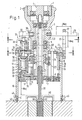
- Figur 1 einen Längsschnitt durch eine erfindungsgemäße Vorrichtung zum Herstellen von Gewindebohrungen in Vollmaterial;
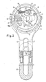
- Figur 2 einen Schnitt durch die Vorrichtung gemäß Figur 1 entlang der Linie II-II;
- Figur 3 einen Schnitt durch die Vorrichtung gemäß Figur 1 entlang der Linie III-III in Figur 1;
- Figur 4 eine Detaildarstellung im vergrößerten Maßstab;
- Figur 5 eine Seitenansicht eines Werkzeuges zur Verwendung in Verbindung mit einer Vorrichtung gemäß Figur 1 bis 4;
- Figur 6 eine Teildarstellung zu Figur 5 im vergrößerten Maßstab.
- An das Gehäuse 1 einer handelsüblichen elektrischen Handbohrmaschnie ist vermittels einer Klemmverschraubung 2 eine Hülse 3 angeschlossen, die eine mit der Abtriebswelle 4 der Handbohrmaschine kuppelbare Werkzeugspindel 5 aufnimmt. In der Hülse 3 ist die Werkzeugspindel 5 über Kugellager 6 abgestützt. Über die Hülse 301 ist die Werkzeugspindel 5 in Ausnehmungen 7 zweier Excenterplatten 8 und 9 aufgenommen. Die Excenterplatten 8 und 9 sind ihrerseits in Ausnehmungen 10 und 11 eines Deckels 12 und eines Bodens 13 eines zylindrischen, ein sogenanntes Spindelgehäuse bildenden Gehäuses 15 drehbar aufgenommen. Ferner sind die Excenterplatten 8 und 9 untereinander, im gezeigten Ausführungsbeispiel mittels Schraubenbolzen 14 und der Hülse 301 drehsicher verbunden. Vermittels der Excenterplatten 8 und 9 kann die Werkzeugspindel 5 radial zur Achse des Spindelgehäuses 15 verstellt werden, so daß Gewindebohrungen unterschiedlichen Durchmessers herstellbar sind. Der Verdrehung der im Spindelgehäuse drehbar gelagerten Excenterplatten ist ein Spindeltrieb 50 zugeordnet, der eine über ein Auge 51 an einen an der Excenterplatte 8 angeordneten Zapfen 52 angeschlossene Schraubspindel 53 sowie eine Spindelmutter 54 umfasst, wobei die Spindelmutter 54 gegen einen drehbar am Deckel 12 des Spindelgehäuses 5 angeordneten Widerlagerbock 56 abgestützt ist. Wie insbesondere aus den Darstellungen der Figuren 2 und 3 ersichtlich ist, sind die Ausnehmungen 10 und 11 für die Aufnahme der Hülse 301 bzw. des Hülsenteiles 301 in den Excenterplatten so angeordnet, daß die Achse 57 des Werkzeuges 39 bwz. der Werkzeugspindel 5 bei keiner Einstellung der Excenterplatten 12 und 13 mit der Achse 58 des Spindelgehäuses zusammenfallen kann, so daß das Werkzeug 39 bei jeder beliebigen Einstellung immer um die Achse 58 des Spindelgehäuses 15 kreisend arbeitet. Das Spindelgehäuse 15 ist in einem im gezeigten Ausführungsbeispiel rohrförmigen Halter 16 vermittels einer Gewindeanordnung 17 axial verstellbar abgestützt. Ferner ist das Spindelgehäuse 15 mit zwei Führunsringen 18 ausgestattet, die an seinem oberen bzw. unteren Ende angeordnet sind und an der Innenumfangsfläche des rohrförmigen Halters 16 anliegen. Die Gewindeanordnung 17 umfasst ein am rohrförmigen Halter 16 angeordnetes Innengewinde 19 und ein am Spindelgehäuse 15 angeordnetes Außengewinde 20. Das Spindelgehäuse 15 ist innerhalb des Halters 16 rotierend angetrieben, wobei von der Werkzeugspindel 5 eine mit dieser kämmende Schnecke 21 angetrieben ist, die ihrerseits über ein Zahnradpaar 22, 23 ein Kegelradgetriebe 24 antreibt, welches den Antrieb vermittels einer Welle 25 auf ein Ritzel 26, das seinerseits mit einem innenverzahnten, im Bereich der oberen Stirnseite des Halters 16 angeordneten Zahnkranz 27 kämmt. Das Kegelradgetriebe 24 umfaßt ein Eingangszahnrad 28 und zwei Ausgangszahnräder 29 und 30, die für vorlaufenden und rücklaufenden Antrieb des Spindelgehäuses 15 wechselweise mit dem Eingangszahnrad 28 in Eingriff bringbar und hierzu in in der Zeichnung nicht im Einzelnen dargestellter Weise auf der Welle 25 axial verschiebbar angeordnet sind. Zur Begrenzung der Arbeitstiefe der Vorrichtung ist ein Drehmomentabschalter 31 vorgesehen, der bei Erreichen der maximal zugelassenen Arbeitstiefe den Drehantrieb des Spindelgehäuses 15 unterbricht. Der Drehmomentabschalter umfaßt im gezeigten Ausführungsbeispiel eine auf die Welle 25 aufschraubbare Mutter 32 und einen mit einem Auslegerarm 33 versehenen Excenter 34, wobei das Ritzel 26 mittels der auf den Excenter 34 wirkenden Mutter 32 kraftschlüssig mit der Welle 25 verspannt wird und der Excenter 34 durch den Auslegerarm 33 in eine unwirksame Lager verstellt wird, wenn die maximal zugelassene Arbeitstiefe erreicht ist, so daß die kraftschlüssige Verbindung zwischen Ritzel 26 und Welle 25 aufgehoben und damit der Drehantrieb des Spindelgehäuses 15 unterbrochen wird. Der Auslegerarm 33 wirkt dabei mit der oberen Stirnfläche des Zahnkranzes 27 zusammen. Der Zahnkranz 27 ist im gezeigten Ausführungsbeispiel oberseitig auf den rohrförmigen Halter 16 aufgesetzt. Die die Werkzeugspindel 5 aufnehmende Hülse 3 ist im gezeigten Ausführungsbeispiel geteilt ausgeführt und umfaßt einen oberen, mit dem Gehäuse 1 der Antriebsmaschine verbindbaren 300 und einen unteren, im Spindelgehäuse 15 bleibend aufgenommenen Teil 301. Am oberen Teil 300 der Hülse 3 ist ein radial ausladender Stützstab 35 starr befestigt, welcher in eine vertikal gerichtete Langlochausnehmung 36 eines am Halter 16 befestigten Bügels 37 eingreift und zusammen mit diesem eine Drehmomentenabstützung bildet. Dabei ist der Stützstab axial und radial verschiebbar in der Langlochausnehmung 36 aufgenommen. Am oberen Teil 300 der Hülse 3 ist weiterhin ein radialer Druckluftanschluß 38 angeordnet, über den Druckluft in die Werkzeugspindel 5 und durch diese hindurch in den unteren Bereich der Spindel 5 und damit zur Arbeitsstelle des Werkzeuges 39 gefördert wird. Zum Austritt der Druckluft und zum Austrag der Späne ist der Halter 16 im Bereich seines unteren Endes mit einer Auslaß- öffnung 40 versehen. An die untere Stirnfläche des Halters 16 ist im gezeigten Ausführungsbeispiel gemäß Figur 1 ferner ein Ring 41 mit darin verstellbar angeordneten, in einer Stellung nach unten vorstehenden Zentrierspitzen 42 angeschlos- sen, über die der Halter 16 in genau ausgerichteter Lage auf dem Werkstück festgelegt werden kann. In der Figur 3 ist ferner gezeigt, daß an den Halter 16 auch noch ein Haltebügel 43 angeschlossen werden kann, welcher ein gabelförmiges Vorderteil 44 aufweist und über dieses vermittels Schrauben 45 an den Halter anschließbar ist. Der Haltebügel 43 kann mit einem ansetzbaren Verlängerungsteil 46 versehen sein und weist zweckmäßigerweise eine längsgerichtete Langlochausnehmung 47 auf, die von einer Befestigungsschraube 48 zum Befestigen des Haltebügels 43 am Werkstück, beispielsweise in einer vorausgehend hergestellten Gewindebohrung durchsetzt ist, um das die Antriebsverbindung Ritzel 26 und Zahnkranz 27, sowie die untere Lagerung der Welle 25 immer spielfrei aufrecht erhalten wird, ist die Halterung jeweils federnd 70 ausgebildet.
- Das in den Figuren 5 und 6 dargestellte Werkzeug 39 ist im Allgemeinen ein Stirnfräser, dessen Schneiden 60 mit Linksdrall angeordnet sind, um ein Mitlauffräsen und damit eine hervorragende Oberflächenqualität zu ermöglichen. Die Schneidenhöhe der Schneiden 60 des Stirnfräsers entspricht der Höhe eines Gewindeganges der Gewindebohrung. Im Abstand zu den Schneiden 60 ist der Stirnfräser mit einer versetzten, als Spänebrecher wirkenden Umfangsnut 61 versehen. Im weiteren Abstand zu den Schneiden 60 des Stirnfräsers ist das Werkzeug 39 mit radial ausladenden Gewindeschneidzähnen 62 versehen. Die Gewindeschneidzähne 62 sind in einer senkrecht zur Achse 63 des Werkzeuges 39 ausgerichteten Ebene 64 angeordnet und weisen eine gleichseitige Querschnittsform mit zur Werkzeugachse koaxialer Stirnfläche 65 auf. Schließlich sind die Schneiden 60 des Stirnfräser im Übergangsbereich zur Umfangsfläche des Stirnfräsers mit einem Radius 66 abgrundet. Beim Einsatz in CNC-Maschinen ist noch für die Entgratung eine 90°-Fläche 67 im Abstand von ca. 1,5 x Ø des zu erstellenden Gewindes vorgesehen. Ferner ist die jeweils erforderliche Zahnhöhe 68 einzuhalten. Anmerkung: Der hier aufgeführte Dräser ist für die Erstellung von metrischem Rechtsgewinde ausgelegt, wobei natürlich alle Schneidflächen den erforderlichen Hinterschliff aufweisen müssen.
Claims (26)
Priority Applications (1)
| Application Number | Priority Date | Filing Date | Title |
|---|---|---|---|
| AT89102213T ATE58662T1 (de) | 1988-03-30 | 1989-02-09 | Vorrichtung und werkzeug zur herstellung aller bekannten gewindearten (ausser saegegewinde) in einem arbeitsgang. |
Applications Claiming Priority (2)
| Application Number | Priority Date | Filing Date | Title |
|---|---|---|---|
| DE19883810884 DE3810884C1 (en) | 1988-03-12 | 1988-03-30 | Apparatus for producing internal threads without predrilling in the solid material |
| DE3810884 | 1988-03-30 |
Publications (3)
| Publication Number | Publication Date |
|---|---|
| EP0335084A2 true EP0335084A2 (de) | 1989-10-04 |
| EP0335084A3 EP0335084A3 (en) | 1990-01-31 |
| EP0335084B1 EP0335084B1 (de) | 1990-11-28 |
Family
ID=6351112
Family Applications (1)
| Application Number | Title | Priority Date | Filing Date |
|---|---|---|---|
| EP89102213A Expired - Lifetime EP0335084B1 (de) | 1988-03-30 | 1989-02-09 | Vorrichtung und Werkzeug zur Herstellung aller bekannten Gewindearten (ausser Sägegewinde) in einem Arbeitsgang |
Country Status (12)
| Country | Link |
|---|---|
| US (1) | US5143492A (de) |
| EP (1) | EP0335084B1 (de) |
| JP (1) | JPH01306124A (de) |
| AT (1) | ATE58662T1 (de) |
| AU (1) | AU624805B2 (de) |
| DD (1) | DD279199A5 (de) |
| DK (1) | DK170969B1 (de) |
| ES (1) | ES2019477B3 (de) |
| FI (1) | FI891133A7 (de) |
| NO (1) | NO175044B (de) |
| WO (1) | WO1989009108A1 (de) |
| ZA (1) | ZA891835B (de) |
Cited By (1)
| Publication number | Priority date | Publication date | Assignee | Title |
|---|---|---|---|---|
| EP1134336A1 (de) | 2000-03-13 | 2001-09-19 | Taiwan Secom Co. Ltd. | Elektronisches Türschloss und dazugehöriger modularer Schlüsselmechanismus |
Families Citing this family (12)
| Publication number | Priority date | Publication date | Assignee | Title |
|---|---|---|---|---|
| US5678962A (en) * | 1994-09-06 | 1997-10-21 | Makino Inc. | Integral boring and threading tool and method |
| US6012882A (en) * | 1995-09-12 | 2000-01-11 | Turchan; Manuel C. | Combined hole making, threading, and chamfering tool with staggered thread cutting teeth |
| CH691291A5 (de) * | 1996-10-29 | 2001-06-29 | Rudolf Gafner | Steuerbarer Werkzeughalter. |
| GB2354470B (en) * | 1999-05-24 | 2004-02-04 | Honda Motor Co Ltd | Cutting tip and manufacturing method thereof |
| US6719681B2 (en) * | 1999-08-06 | 2004-04-13 | Econova, Inc. | Methods for centrifugally separating mixed components of a fluid stream |
| US6567514B2 (en) * | 2001-01-17 | 2003-05-20 | Sbc Technology Resources, Inc. | Method and system for processing telephone calls via a remote tie-line |
| IL167779A (en) * | 2005-03-31 | 2013-09-30 | Hanita Metal Works Ltd | Milling balls |
| US8419556B2 (en) | 2008-08-27 | 2013-04-16 | Honda Motor Co., Ltd. | Nut, female thread machining device and female thread machining method |
| US10875201B2 (en) | 2018-04-04 | 2020-12-29 | Swanstrom Tools Usa Inc. | Relief guard for hand tools |
| RU2760768C2 (ru) * | 2019-11-22 | 2021-11-30 | Федеральное государственное бюджетное образовательное учреждение высшего образования "Юго-Западный государственный университет" (ЮЗГУ) | Способ нарезания винтовых канавок на внутренней поверхности цилиндрической оболочки и устройство для его осуществления |
| CN113086477A (zh) * | 2021-04-12 | 2021-07-09 | 东方电气集团科学技术研究院有限公司 | 一种混合料库人工辅助存取料筒传输装置 |
| CN115609698B (zh) * | 2022-10-20 | 2024-05-14 | 合肥楠达建筑工程有限公司 | 一种用于集装箱底板预处理的转运设备 |
Family Cites Families (24)
| Publication number | Priority date | Publication date | Assignee | Title |
|---|---|---|---|---|
| US1408578A (en) * | 1922-03-07 | Pobtable cylinder gbinber | ||
| FR469152A (fr) * | 1914-03-02 | 1914-07-25 | Cie De Fives Lille | Machine portative pour fileter intérieurement à la fraise |
| US1237255A (en) * | 1917-04-07 | 1917-08-14 | John Schmidt | Grinding-machine. |
| US1252162A (en) * | 1917-04-14 | 1918-01-01 | Joseph Pauer | Grinding-machine. |
| US1263559A (en) * | 1917-05-14 | 1918-04-23 | Henry Kaetker | Cylinder-grinder. |
| US1316718A (en) * | 1918-06-07 | 1919-09-23 | Peter P-G Hall | Planetary metal-working machine. |
| US1562969A (en) * | 1922-12-01 | 1925-11-24 | Jordan Machine Tool Company | Reboring and grinding machine for engine cylinders |
| US2451497A (en) * | 1944-09-22 | 1948-10-19 | Frederick J Kratchman | Thread miller |
| US3526167A (en) * | 1968-05-23 | 1970-09-01 | Fresco Ind Inc | Multi-purpose milling heads |
| US3690220A (en) * | 1970-04-29 | 1972-09-12 | Fresco Ind Inc | Helically-tracking milling assembly with tiltable thread cutting head |
| DE2346809C3 (de) * | 1973-09-18 | 1983-05-19 | Burgsmüller, Karl, 3350 Kreiensen | An feststende Werkstücke verbring- und über einen mit ihrem verbindbaren Unterbau ansetzbare Vorrichtung zum Wirbeln von Innengewinden |
| DE2516775A1 (de) * | 1975-04-16 | 1976-10-28 | Leitz Ernst Gmbh | Einrichtung zum gewindefraesen |
| US4125057A (en) * | 1976-03-31 | 1978-11-14 | Cox Kris E | Planetary milling machine |
| JPS5853974B2 (ja) * | 1978-10-20 | 1983-12-02 | 本田技研工業株式会社 | 鋳抜き穴用タツプ工具 |
| DD143740B1 (de) * | 1979-05-23 | 1983-06-15 | Gunter Seipt | Verfahren zum fraesen von innengewinde |
| JPS58192718A (ja) * | 1982-05-04 | 1983-11-10 | Mitsubishi Heavy Ind Ltd | めねじ加工装置 |
| JPS5930617A (ja) * | 1982-08-10 | 1984-02-18 | Mitsubishi Heavy Ind Ltd | めねじ加工装置 |
| DE3527971A1 (de) * | 1985-08-03 | 1987-03-12 | Felix Leeb | Grossloch - bohrvorrichtung |
| DE3786096T2 (de) * | 1986-03-13 | 1993-10-14 | Turchan Manuel C | Methode und Werkzeug zum Gewindeschneidbohren. |
| US4761844A (en) * | 1986-03-17 | 1988-08-09 | Turchan Manuel C | Combined hole making and threading tool |
| US4934040A (en) * | 1986-07-10 | 1990-06-19 | Turchan Manuel C | Spindle driver for machine tools |
| DE8803565U1 (de) * | 1988-03-16 | 1988-09-01 | Prototyp-Werke GmbH, Fabrik für Präzisionswerkzeuge, 7615 Zell | Gewindefraeser |
| DE3828780A1 (de) * | 1988-08-25 | 1990-03-01 | Schmitt M Norbert Dipl Kaufm D | Bohrgewindefraeser |
| DE3939795A1 (de) * | 1989-12-01 | 1991-06-06 | Schmitt M Norbert Dipl Kaufm D | Verfahren zur herstellung einer gewindebohrung |
-
1989
- 1989-02-09 AT AT89102213T patent/ATE58662T1/de not_active IP Right Cessation
- 1989-02-09 ES ES89102213T patent/ES2019477B3/es not_active Expired - Lifetime
- 1989-02-09 EP EP89102213A patent/EP0335084B1/de not_active Expired - Lifetime
- 1989-02-22 NO NO890745A patent/NO175044B/no not_active IP Right Cessation
- 1989-03-02 AU AU30978/89A patent/AU624805B2/en not_active Ceased
- 1989-03-03 WO PCT/DE1989/000128 patent/WO1989009108A1/de not_active Ceased
- 1989-03-09 FI FI891133A patent/FI891133A7/fi not_active Application Discontinuation
- 1989-03-09 DK DK113889A patent/DK170969B1/da not_active IP Right Cessation
- 1989-03-10 ZA ZA891835A patent/ZA891835B/xx unknown
- 1989-03-10 DD DD89326452A patent/DD279199A5/de not_active IP Right Cessation
- 1989-03-10 JP JP1056523A patent/JPH01306124A/ja active Pending
-
1991
- 1991-06-27 US US07/726,711 patent/US5143492A/en not_active Expired - Fee Related
Cited By (1)
| Publication number | Priority date | Publication date | Assignee | Title |
|---|---|---|---|---|
| EP1134336A1 (de) | 2000-03-13 | 2001-09-19 | Taiwan Secom Co. Ltd. | Elektronisches Türschloss und dazugehöriger modularer Schlüsselmechanismus |
Also Published As
| Publication number | Publication date |
|---|---|
| ATE58662T1 (de) | 1990-12-15 |
| ZA891835B (en) | 1990-01-31 |
| NO175044B (no) | 1994-05-16 |
| DK170969B1 (da) | 1996-04-09 |
| NO890745L (no) | 1989-10-02 |
| ES2019477B3 (es) | 1991-06-16 |
| DK113889A (da) | 1989-10-01 |
| NO175044C (de) | 1994-08-24 |
| JPH01306124A (ja) | 1989-12-11 |
| FI891133L (fi) | 1989-10-01 |
| DD279199A5 (de) | 1990-05-30 |
| NO890745D0 (no) | 1989-02-22 |
| FI891133A0 (fi) | 1989-03-09 |
| EP0335084A3 (en) | 1990-01-31 |
| AU3097889A (en) | 1989-10-05 |
| WO1989009108A1 (fr) | 1989-10-05 |
| DK113889D0 (da) | 1989-03-09 |
| US5143492A (en) | 1992-09-01 |
| EP0335084B1 (de) | 1990-11-28 |
| AU624805B2 (en) | 1992-06-25 |
| FI891133A7 (fi) | 1989-10-01 |
Similar Documents
| Publication | Publication Date | Title |
|---|---|---|
| DE10163473C1 (de) | Werkzeug zur spanabtragenden Bearbeitung von Rohrenden | |
| EP0103291A1 (de) | Bohr- und Entgratkopf und darin einspannbares Bohr- und Entgratwerkzeug und Verfahren zum Bohren und Entgraten eines Werkstücks | |
| DE3240165A1 (de) | Werkzeugmaschine zum gleichzeitigen fraesen mehrerer flaechen vom freien ende eines werkstuecks her | |
| EP0335084A2 (de) | Vorrichtung und Werkzeug zur Herstellung aller bekannten Gewindearten (ausser Sägegewinde) in einem Arbeitsgang | |
| DE8803565U1 (de) | Gewindefraeser | |
| DE4021090C2 (de) | Bearbeitungsvorrichtung mit Mitteln zur Änderung der radialen Position von Schneidwerkzeugen | |
| DE7728438U1 (de) | Stirnmesserkopf zum Verzahnen von Zahnrädern | |
| DE3727103C2 (de) | ||
| EP1239995A1 (de) | Verfahren und vorrichtung zum schleifen von genuteten werkzeugen | |
| DE3001206C2 (de) | ||
| DE3810884C1 (en) | Apparatus for producing internal threads without predrilling in the solid material | |
| DE8804806U1 (de) | Vorrichtung und Werkzeug zur Herstellung aller bekannten Gewindearten (außer Sägegewinde) in einem Arbeitsgang | |
| DE10147649C2 (de) | Fräsaggregat | |
| DE3707022C2 (de) | ||
| DE2620383C2 (de) | Einsatzwerkzeug für Handbohrmaschinen | |
| DE19841579C2 (de) | Werkzeug zur spanenden Bearbeitung mit geometrisch bestimmten Schneiden | |
| DE2204137A1 (de) | Planeinstechwerkzeug | |
| DE2810393C3 (de) | Kantenbearbeitungsvorrichtung mit einem umlaufenden Werkzeug | |
| DE161504C (de) | ||
| DE29502537U1 (de) | Vorrichtung zur insbesondere spanenden Bearbeitung eines Werkstückes | |
| DE9309505U1 (de) | Vorrichtung zur spanabhebenden herstellung von profilen, insbesondere von polygonprofilen | |
| EP1396319B1 (de) | Bohrer | |
| DE187887C (de) | ||
| DE2032026A1 (de) | Gerät, insbesondere Zusatzgerät zur Herstellung von runden Ausnehmungen in Materialien, wie z.B. Blech | |
| DE102004037562B4 (de) | Aufbohrwerkzeug |
Legal Events
| Date | Code | Title | Description |
|---|---|---|---|
| PUAI | Public reference made under article 153(3) epc to a published international application that has entered the european phase |
Free format text: ORIGINAL CODE: 0009012 |
|
| AK | Designated contracting states |
Kind code of ref document: A2 Designated state(s): AT BE CH ES FR GB GR IT LI LU NL SE |
|
| PUAL | Search report despatched |
Free format text: ORIGINAL CODE: 0009013 |
|
| AK | Designated contracting states |
Kind code of ref document: A3 Designated state(s): AT BE CH ES FR GB GR IT LI LU NL SE |
|
| 17P | Request for examination filed |
Effective date: 19891228 |
|
| 17Q | First examination report despatched |
Effective date: 19900504 |
|
| GRAA | (expected) grant |
Free format text: ORIGINAL CODE: 0009210 |
|
| AK | Designated contracting states |
Kind code of ref document: B1 Designated state(s): AT BE CH ES FR GB GR IT LI LU NL SE |
|
| PG25 | Lapsed in a contracting state [announced via postgrant information from national office to epo] |
Ref country code: GR Free format text: LAPSE BECAUSE OF FAILURE TO SUBMIT A TRANSLATION OF THE DESCRIPTION OR TO PAY THE FEE WITHIN THE PRESCRIBED TIME-LIMIT Effective date: 19901128 |
|
| REF | Corresponds to: |
Ref document number: 58662 Country of ref document: AT Date of ref document: 19901215 Kind code of ref document: T |
|
| ITF | It: translation for a ep patent filed | ||
| ITTA | It: last paid annual fee | ||
| PG25 | Lapsed in a contracting state [announced via postgrant information from national office to epo] |
Ref country code: LU Free format text: LAPSE BECAUSE OF NON-PAYMENT OF DUE FEES Effective date: 19910228 |
|
| GBT | Gb: translation of ep patent filed (gb section 77(6)(a)/1977) | ||
| ET | Fr: translation filed | ||
| PLBE | No opposition filed within time limit |
Free format text: ORIGINAL CODE: 0009261 |
|
| STAA | Information on the status of an ep patent application or granted ep patent |
Free format text: STATUS: NO OPPOSITION FILED WITHIN TIME LIMIT |
|
| 26N | No opposition filed | ||
| EAL | Se: european patent in force in sweden |
Ref document number: 89102213.9 |
|
| REG | Reference to a national code |
Ref country code: GB Ref legal event code: IF02 |
|
| PGFP | Annual fee paid to national office [announced via postgrant information from national office to epo] |
Ref country code: GB Payment date: 20030130 Year of fee payment: 15 |
|
| PGFP | Annual fee paid to national office [announced via postgrant information from national office to epo] |
Ref country code: BE Payment date: 20030213 Year of fee payment: 15 |
|
| PGFP | Annual fee paid to national office [announced via postgrant information from national office to epo] |
Ref country code: AT Payment date: 20030214 Year of fee payment: 15 |
|
| PGFP | Annual fee paid to national office [announced via postgrant information from national office to epo] |
Ref country code: SE Payment date: 20030218 Year of fee payment: 15 |
|
| PGFP | Annual fee paid to national office [announced via postgrant information from national office to epo] |
Ref country code: CH Payment date: 20030219 Year of fee payment: 15 |
|
| PGFP | Annual fee paid to national office [announced via postgrant information from national office to epo] |
Ref country code: NL Payment date: 20030228 Year of fee payment: 15 |
|
| PG25 | Lapsed in a contracting state [announced via postgrant information from national office to epo] |
Ref country code: AT Free format text: LAPSE BECAUSE OF NON-PAYMENT OF DUE FEES Effective date: 20040209 Ref country code: GB Free format text: LAPSE BECAUSE OF NON-PAYMENT OF DUE FEES Effective date: 20040209 |
|
| PG25 | Lapsed in a contracting state [announced via postgrant information from national office to epo] |
Ref country code: SE Free format text: LAPSE BECAUSE OF NON-PAYMENT OF DUE FEES Effective date: 20040210 |
|
| PG25 | Lapsed in a contracting state [announced via postgrant information from national office to epo] |
Ref country code: BE Free format text: LAPSE BECAUSE OF NON-PAYMENT OF DUE FEES Effective date: 20040228 |
|
| PG25 | Lapsed in a contracting state [announced via postgrant information from national office to epo] |
Ref country code: LI Free format text: LAPSE BECAUSE OF NON-PAYMENT OF DUE FEES Effective date: 20040229 Ref country code: CH Free format text: LAPSE BECAUSE OF NON-PAYMENT OF DUE FEES Effective date: 20040229 |
|
| BERE | Be: lapsed |
Owner name: *LEEB FELIX Effective date: 20040228 |
|
| PG25 | Lapsed in a contracting state [announced via postgrant information from national office to epo] |
Ref country code: NL Free format text: LAPSE BECAUSE OF NON-PAYMENT OF DUE FEES Effective date: 20040901 |
|
| EUG | Se: european patent has lapsed | ||
| GBPC | Gb: european patent ceased through non-payment of renewal fee |
Effective date: 20040209 |
|
| REG | Reference to a national code |
Ref country code: CH Ref legal event code: PL |
|
| NLV4 | Nl: lapsed or anulled due to non-payment of the annual fee |
Effective date: 20040901 |
|
| PGFP | Annual fee paid to national office [announced via postgrant information from national office to epo] |
Ref country code: FR Payment date: 20050224 Year of fee payment: 17 |
|
| PGFP | Annual fee paid to national office [announced via postgrant information from national office to epo] |
Ref country code: ES Payment date: 20060202 Year of fee payment: 18 |
|
| PGFP | Annual fee paid to national office [announced via postgrant information from national office to epo] |
Ref country code: IT Payment date: 20060228 Year of fee payment: 18 |
|
| REG | Reference to a national code |
Ref country code: FR Ref legal event code: ST Effective date: 20071030 |
|
| PG25 | Lapsed in a contracting state [announced via postgrant information from national office to epo] |
Ref country code: FR Free format text: LAPSE BECAUSE OF NON-PAYMENT OF DUE FEES Effective date: 20070228 |
|
| REG | Reference to a national code |
Ref country code: ES Ref legal event code: FD2A Effective date: 20070210 |
|
| PG25 | Lapsed in a contracting state [announced via postgrant information from national office to epo] |
Ref country code: ES Free format text: LAPSE BECAUSE OF NON-PAYMENT OF DUE FEES Effective date: 20070210 |
|
| PG25 | Lapsed in a contracting state [announced via postgrant information from national office to epo] |
Ref country code: FR Free format text: LAPSE BECAUSE OF NON-PAYMENT OF DUE FEES Effective date: 20060228 |
|
| PG25 | Lapsed in a contracting state [announced via postgrant information from national office to epo] |
Ref country code: IT Free format text: LAPSE BECAUSE OF NON-PAYMENT OF DUE FEES Effective date: 20070209 |