EP0334870B1 - Verfahren und maschine zur beschichtung von rohren - Google Patents
Verfahren und maschine zur beschichtung von rohren Download PDFInfo
- Publication number
- EP0334870B1 EP0334870B1 EP87907801A EP87907801A EP0334870B1 EP 0334870 B1 EP0334870 B1 EP 0334870B1 EP 87907801 A EP87907801 A EP 87907801A EP 87907801 A EP87907801 A EP 87907801A EP 0334870 B1 EP0334870 B1 EP 0334870B1
- Authority
- EP
- European Patent Office
- Prior art keywords
- lining
- centrifugal
- pipe
- composition
- lining machine
- Prior art date
- Legal status (The legal status is an assumption and is not a legal conclusion. Google has not performed a legal analysis and makes no representation as to the accuracy of the status listed.)
- Expired - Lifetime
Links
- 238000000034 method Methods 0.000 title claims abstract description 16
- 239000000203 mixture Substances 0.000 claims abstract description 58
- 238000004873 anchoring Methods 0.000 claims abstract description 5
- 238000002156 mixing Methods 0.000 claims description 33
- 238000009499 grossing Methods 0.000 claims description 11
- 239000000463 material Substances 0.000 claims description 8
- 239000000470 constituent Substances 0.000 claims description 7
- 230000009471 action Effects 0.000 claims description 5
- 238000003780 insertion Methods 0.000 claims description 3
- 230000037431 insertion Effects 0.000 claims description 3
- 238000000605 extraction Methods 0.000 claims description 2
- 239000011347 resin Substances 0.000 description 10
- 229920005989 resin Polymers 0.000 description 10
- 239000004033 plastic Substances 0.000 description 5
- 229920003023 plastic Polymers 0.000 description 5
- 239000004848 polyfunctional curative Substances 0.000 description 5
- 238000009412 basement excavation Methods 0.000 description 4
- 229920003266 Leaf® Polymers 0.000 description 3
- 239000003795 chemical substances by application Substances 0.000 description 3
- 230000000694 effects Effects 0.000 description 3
- 239000011256 inorganic filler Substances 0.000 description 3
- 229910003475 inorganic filler Inorganic materials 0.000 description 3
- 238000004140 cleaning Methods 0.000 description 2
- 230000008878 coupling Effects 0.000 description 2
- 238000010168 coupling process Methods 0.000 description 2
- 238000005859 coupling reaction Methods 0.000 description 2
- 239000003822 epoxy resin Substances 0.000 description 2
- 230000007246 mechanism Effects 0.000 description 2
- 238000012986 modification Methods 0.000 description 2
- 230000004048 modification Effects 0.000 description 2
- 229920000647 polyepoxide Polymers 0.000 description 2
- 230000008439 repair process Effects 0.000 description 2
- 229920000298 Cellophane Polymers 0.000 description 1
- 229920002678 cellulose Polymers 0.000 description 1
- 239000001913 cellulose Substances 0.000 description 1
- 239000011248 coating agent Substances 0.000 description 1
- 238000000576 coating method Methods 0.000 description 1
- KAATUXNTWXVJKI-UHFFFAOYSA-N cypermethrin Chemical compound CC1(C)C(C=C(Cl)Cl)C1C(=O)OC(C#N)C1=CC=CC(OC=2C=CC=CC=2)=C1 KAATUXNTWXVJKI-UHFFFAOYSA-N 0.000 description 1
- 230000001419 dependent effect Effects 0.000 description 1
- 239000006260 foam Substances 0.000 description 1
- 239000002783 friction material Substances 0.000 description 1
- 238000011065 in-situ storage Methods 0.000 description 1
- 230000014759 maintenance of location Effects 0.000 description 1
- 239000002184 metal Substances 0.000 description 1
- 229920000642 polymer Polymers 0.000 description 1
- 239000004814 polyurethane Substances 0.000 description 1
- 229920002635 polyurethane Polymers 0.000 description 1
- 239000007921 spray Substances 0.000 description 1
- 230000001360 synchronised effect Effects 0.000 description 1
- 238000011144 upstream manufacturing Methods 0.000 description 1
- 230000000007 visual effect Effects 0.000 description 1
Images


Classifications
-
- F—MECHANICAL ENGINEERING; LIGHTING; HEATING; WEAPONS; BLASTING
- F16—ENGINEERING ELEMENTS AND UNITS; GENERAL MEASURES FOR PRODUCING AND MAINTAINING EFFECTIVE FUNCTIONING OF MACHINES OR INSTALLATIONS; THERMAL INSULATION IN GENERAL
- F16L—PIPES; JOINTS OR FITTINGS FOR PIPES; SUPPORTS FOR PIPES, CABLES OR PROTECTIVE TUBING; MEANS FOR THERMAL INSULATION IN GENERAL
- F16L55/00—Devices or appurtenances for use in, or in connection with, pipes or pipe systems
- F16L55/16—Devices for covering leaks in pipes or hoses, e.g. hose-menders
- F16L55/162—Devices for covering leaks in pipes or hoses, e.g. hose-menders from inside the pipe
- F16L55/165—Devices for covering leaks in pipes or hoses, e.g. hose-menders from inside the pipe a pipe or flexible liner being inserted in the damaged section
- F16L55/1652—Devices for covering leaks in pipes or hoses, e.g. hose-menders from inside the pipe a pipe or flexible liner being inserted in the damaged section the flexible liner being pulled into the damaged section
- F16L55/1653—Devices for covering leaks in pipes or hoses, e.g. hose-menders from inside the pipe a pipe or flexible liner being inserted in the damaged section the flexible liner being pulled into the damaged section and being pressed into contact with the pipe by a tool which moves inside along the pipe
-
- F—MECHANICAL ENGINEERING; LIGHTING; HEATING; WEAPONS; BLASTING
- F16—ENGINEERING ELEMENTS AND UNITS; GENERAL MEASURES FOR PRODUCING AND MAINTAINING EFFECTIVE FUNCTIONING OF MACHINES OR INSTALLATIONS; THERMAL INSULATION IN GENERAL
- F16L—PIPES; JOINTS OR FITTINGS FOR PIPES; SUPPORTS FOR PIPES, CABLES OR PROTECTIVE TUBING; MEANS FOR THERMAL INSULATION IN GENERAL
- F16L55/00—Devices or appurtenances for use in, or in connection with, pipes or pipe systems
- F16L55/16—Devices for covering leaks in pipes or hoses, e.g. hose-menders
- F16L55/162—Devices for covering leaks in pipes or hoses, e.g. hose-menders from inside the pipe
- F16L55/1645—Devices for covering leaks in pipes or hoses, e.g. hose-menders from inside the pipe a sealing material being introduced inside the pipe by means of a tool moving in the pipe
-
- B—PERFORMING OPERATIONS; TRANSPORTING
- B05—SPRAYING OR ATOMISING IN GENERAL; APPLYING FLUENT MATERIALS TO SURFACES, IN GENERAL
- B05C—APPARATUS FOR APPLYING FLUENT MATERIALS TO SURFACES, IN GENERAL
- B05C7/00—Apparatus specially designed for applying liquid or other fluent material to the inside of hollow work
- B05C7/02—Apparatus specially designed for applying liquid or other fluent material to the inside of hollow work the liquid or other fluent material being projected
-
- Y—GENERAL TAGGING OF NEW TECHNOLOGICAL DEVELOPMENTS; GENERAL TAGGING OF CROSS-SECTIONAL TECHNOLOGIES SPANNING OVER SEVERAL SECTIONS OF THE IPC; TECHNICAL SUBJECTS COVERED BY FORMER USPC CROSS-REFERENCE ART COLLECTIONS [XRACs] AND DIGESTS
- Y10—TECHNICAL SUBJECTS COVERED BY FORMER USPC
- Y10S—TECHNICAL SUBJECTS COVERED BY FORMER USPC CROSS-REFERENCE ART COLLECTIONS [XRACs] AND DIGESTS
- Y10S118/00—Coating apparatus
- Y10S118/10—Pipe and tube inside
-
- Y—GENERAL TAGGING OF NEW TECHNOLOGICAL DEVELOPMENTS; GENERAL TAGGING OF CROSS-SECTIONAL TECHNOLOGIES SPANNING OVER SEVERAL SECTIONS OF THE IPC; TECHNICAL SUBJECTS COVERED BY FORMER USPC CROSS-REFERENCE ART COLLECTIONS [XRACs] AND DIGESTS
- Y10—TECHNICAL SUBJECTS COVERED BY FORMER USPC
- Y10S—TECHNICAL SUBJECTS COVERED BY FORMER USPC CROSS-REFERENCE ART COLLECTIONS [XRACs] AND DIGESTS
- Y10S138/00—Pipes and tubular conduits
- Y10S138/07—Resins
-
- Y—GENERAL TAGGING OF NEW TECHNOLOGICAL DEVELOPMENTS; GENERAL TAGGING OF CROSS-SECTIONAL TECHNOLOGIES SPANNING OVER SEVERAL SECTIONS OF THE IPC; TECHNICAL SUBJECTS COVERED BY FORMER USPC CROSS-REFERENCE ART COLLECTIONS [XRACs] AND DIGESTS
- Y10—TECHNICAL SUBJECTS COVERED BY FORMER USPC
- Y10T—TECHNICAL SUBJECTS COVERED BY FORMER US CLASSIFICATION
- Y10T156/00—Adhesive bonding and miscellaneous chemical manufacture
- Y10T156/10—Methods of surface bonding and/or assembly therefor
- Y10T156/1052—Methods of surface bonding and/or assembly therefor with cutting, punching, tearing or severing
- Y10T156/1062—Prior to assembly
- Y10T156/1067—Continuous longitudinal slitting
-
- Y—GENERAL TAGGING OF NEW TECHNOLOGICAL DEVELOPMENTS; GENERAL TAGGING OF CROSS-SECTIONAL TECHNOLOGIES SPANNING OVER SEVERAL SECTIONS OF THE IPC; TECHNICAL SUBJECTS COVERED BY FORMER USPC CROSS-REFERENCE ART COLLECTIONS [XRACs] AND DIGESTS
- Y10—TECHNICAL SUBJECTS COVERED BY FORMER USPC
- Y10T—TECHNICAL SUBJECTS COVERED BY FORMER US CLASSIFICATION
- Y10T156/00—Adhesive bonding and miscellaneous chemical manufacture
- Y10T156/17—Surface bonding means and/or assemblymeans with work feeding or handling means
- Y10T156/1788—Work traversing type and/or means applying work to wall or static structure
- Y10T156/179—Work traversing type and/or means applying work to wall or static structure with liquid applying means
-
- Y—GENERAL TAGGING OF NEW TECHNOLOGICAL DEVELOPMENTS; GENERAL TAGGING OF CROSS-SECTIONAL TECHNOLOGIES SPANNING OVER SEVERAL SECTIONS OF THE IPC; TECHNICAL SUBJECTS COVERED BY FORMER USPC CROSS-REFERENCE ART COLLECTIONS [XRACs] AND DIGESTS
- Y10—TECHNICAL SUBJECTS COVERED BY FORMER USPC
- Y10T—TECHNICAL SUBJECTS COVERED BY FORMER US CLASSIFICATION
- Y10T156/00—Adhesive bonding and miscellaneous chemical manufacture
- Y10T156/17—Surface bonding means and/or assemblymeans with work feeding or handling means
- Y10T156/1788—Work traversing type and/or means applying work to wall or static structure
- Y10T156/1795—Implement carried web supply
-
- Y—GENERAL TAGGING OF NEW TECHNOLOGICAL DEVELOPMENTS; GENERAL TAGGING OF CROSS-SECTIONAL TECHNOLOGIES SPANNING OVER SEVERAL SECTIONS OF THE IPC; TECHNICAL SUBJECTS COVERED BY FORMER USPC CROSS-REFERENCE ART COLLECTIONS [XRACs] AND DIGESTS
- Y10—TECHNICAL SUBJECTS COVERED BY FORMER USPC
- Y10T—TECHNICAL SUBJECTS COVERED BY FORMER US CLASSIFICATION
- Y10T156/00—Adhesive bonding and miscellaneous chemical manufacture
- Y10T156/17—Surface bonding means and/or assemblymeans with work feeding or handling means
- Y10T156/1798—Surface bonding means and/or assemblymeans with work feeding or handling means with liquid adhesive or adhesive activator applying means
Definitions
- This invention relates to a method of and apparatus for lining pipes, especially but not exclusively sewer or gas pipes.
- the invention is concerned with improvements in or modifications of the pipe lining methods and apparatus disclosed in our PCT Patent Application No. PCT/GB86/00486 filed 14th August 1986 (Publication No. WO87/01173 dated 26 February 1987).
- apparatus for lining a pipe with a settable lining composition contained in hose means laid along the pipe comprising a centrifugal lining machine having inlet means for the settable lining composition, delivery tube means connected, at one end, to the inlet means and adapted, at the other end, for insertion into the hose means filled with the settable lining composition, and hose-slitting means at or adjacent the other end of the delivery tube means for axially slitting the hose means as the delivery tube means is urged into the hose means, whereby the settable lining composition can flow from the hose means into the delivery tube means and thence to the centrifugal lining machine.
- each hose is preferably such as to provide the quantity of resin and hardener sufficient to give a predetermined thickness of structural lining on the pipe wall. Such a thickness may, for example, be within the range of 1% to 5% of the pipe diameter.
- a trowelling or smoothing method which employs as a trowelling medium a flexible thin-walled tube applied under pressure against the structurally-lined pipe wall, prior to setting or curing of settable lining composition, to remove any orange peel effect from the structural lining.
- This trowelling tube which may be a cellulose polymer such as CELLOPHANE (Trade Mark), may be removed or simply left in situ .
- the present invention is also concerned with improvements in or modifications of this trowelling method and the trowelling arrangement for effecting same.
- a method of lining a pipe comprising the steps of laying hose means along the bottom of a pipe to be lined, the hose means having been filled with a predetermined quantity of settable lining composition, anchoring the hose means at each end along the bottom of the pipe, advancing a centrifugal lining machine along the length of the hose means, slitting the hose means in front of the advancing centrifugal lining machine to permit egress of the lining composition from the hose means, delivering the admixed settable composition to a centrifugal impellor of the centrifugal lining machine for application of the settable composition to the pipe wall as the centrifugal lining machine advances along the pipe, and guiding the slit and emptied hose means through a central axial bore extending the length of the centrifugal lining machine to lie in a flattened condition on the bottom of the lined pipe wall rearwardly of the centrifugal lining machine.
- the method comprises the step of trowelling or smoothing the applied lining composition by means of a tube of flexible thin-walled material housed in open tube manner in an annular housing surrounding an axial bore of a smoothing trowel trailed behind the centrifugal lining machine in terms of lining machine advancement, the two axial bores being aligned, and the trowelling action being effected by anchoring one end of the tube of flexible thin-walled material within the pipe at a location constituting a starting point for a pipe-lining run, advancing the centrifugal lining machine and smoothing trowel along the pipe to cause extraction of the flexible thin-walled tube through an open end of the annular housing adjacent the lining machine for movement around and rearwardly of the smoothing trowel which applies the flexible thin-walled tube under pressure against the applied lining composition rearwardly of the lining machine.
- apparatus for lining a pipe with a settable lining composition contained in hose means laid along the pipe comprising a centrifugal lining machine having a central axial bore extending the length thereof, inlet means for the settable lining composition, delivery tube means connected, at one end, to the inlet means and adapted, at the other end, for insertion into the hose means filled with the settable lining composition, and hose-slitting means at or adjacent the other end of the delivery tube means for axially slitting the hose means as the delivery tube means is urged into the hose means, whereby the settable lining composition can flow from the hose means into the delivery tube means and thence to the centrifugal lining machine, while the slit and emptied hoses pass through the axial bore to be disposed on the now-lined wall of the pipe.
- the delivery tube means comprises a pair of delivery tubes, each for a respective component constituent of a two-shot resinous settable lining composition, communicating with a mixing chamber containing a rotatable mixing and agitating arrangement, which chamber, in turn, communicates with a centrifugal impellor of the centrifugal lining machine, the mixing and agitating arrangement and the centrifugal impellor being rotated in opposite directions at different speeds by separate driving means.
- centrifugal impellor is driven at a relatively high speed while the mixing and agitating arrangement is driven at a relatively low speed.
- the driving means in each case, is a plurality of air vane motors coupled to the centrifugal impellor and the mixing and agitating arrangement respectively via gearing, the respective air vane motors being at opposite ends of the centrifugal lining machine.
- the motive air pressure is fed to the air vane motors of the mixing and agitating arrangement via an air delivery hose or pipe and an annular distribution chamber which communicates with an axial annular chamber to deliver pressurised air to the air vane motors driving the centrifugal impellor.
- the exhaust air from the centrifugal impellor air vane motors is returned via an axial annular chamber concentric with the air delivery axial annular chamber for exhaust at the leading end of the centrifugal lining machine.
- a smoothing trowel is connected to the rear of the lining machine and comprises an axial bore aligned with the axial bore of the lining machine and surrounded by an annular housing for containing in open tube manner a tube of flexible thin-walled material, the annular housing being open at its end nearer the lining machine for egress of the flexible thin-walled tube.
- the air motor arrangement 22 is housed within a stationary surrounding casing 25 and the agitating arrangement 23 is housed within a stationary surrounding casing 26, which casing 26 constitutes the outer wall of a mixing chamber 27 within which the agitating arrangement 23 operates.
- the lining composition used with the lining apparatus according to the present invention is constituted by a resin component and a hardener component contained within prefilled plastics hoses which are laid along the length of a sewer pipe to be lined, the hoses being anchored at each end.
- the hoses constitute a pair of parallel rails along which the lining apparatus according to the present invention is advanced.
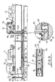
- the apparatus also comprises two parallel delivery tubes 28 at the leading end of the apparatus in terms of the direction of apparatus advancement along the sewer pipe.
- These delivery tubes 28 are open at their leading end and are generally of circular cross-section at that end. They extend rearwardly of the apparatus to communicate with the mixing chamber 27, the cross-sectional shape of the delivery tubes 28 changing from circular at the leading end to kidney-shaped as can be seen in Figs. 2 and 4 to merge with the mixing chamber 27.
- Each delivery tube 28 at its outside mounts a blade holder 29 which supports a pair of axially spaced removable and replaceable blades 30.
- a carriage 32 having fore-and-aft wheels 33, 34 which are eccentrically mounted to permit fine tuning of the height of the apparatus relative to the sewer pipe.
- the carriage 32 extends from the region of the mixing chamber 27 to the leading end of the delivery tubes 28.
- a lateral plate 35 provided with a hole 36 whereby a yoke (not shown) can be attached to the carriage 32.
- a pulling cable or rope is attached to the yoke at one end and to a powered winch at the other end, the winch being located at ground level and the cable extending from the yoke along the sewer pipe 31 and up the "home" hole or excavation. Operation of the winch advances the lining apparatus at a controlled rate along the sewer pipe 31.
- the cutting blades are used, as will be described later, to split the prefilled lining composition hoses to allow the content thereof to flow along the delivery tubes 28 into the mixing chamber 27 whereat the two components (resin and hardener) of the lining composition are intimately and thoroughly mixed prior to flowing into the centrifugal impellor 21 for centrifugal distribution to a predetermined thickness onto the wall of the sewer pipe 31.
- the applied lining is indicated by the reference 37.
- the air motor arrangement 24 comprises four individual air vane motors 38 (see Fig. 2) each of, say, 0.8 horse power (597 W) capacity giving a total drive input of 3.2 horse power (2386 W).
- An air delivery hose 39 is coupled to one of the air motors 38 by a quick-release coupling 40.
- This air hose 39 like the pulling cable or rope extends along the sewer pipe and up the "home" hole or excavation to the winch which reels in the air hose 39 as the lining apparatus advances towards the "home" hole or excavation.
- the other end of the air hose 39 is coupled to compressor means at ground level.
- the air delivered to said one air motor 38 is fed to the other three air motors 38 via an annular distribution chamber 41 (Figs. 6 and 7).
- Each motor drives a gearwheel 42 meshing with a ring gear 43 surrounding the non-rotatable stationary the tube 20.
- This ring gear constitutes part of an annular rotatable hub 44 keyed to a radially extending flange 45 from which extends a series of equi-angularly spaced rods or pins 46 which extends from the flange axially and forwardly of the apparatus into the mixing chamber 27 the rods or pins 46 mounting cross or radial pins 47 which act as agitating or mixing elements within the mixing chamber 27.
- the gear ratios 42, 43 are selected such that the agitating and mixing arrangement 23 rotates at say 440 rpm in, for example, an anti-clockwise direction.
- the centrifugal impellor is diametrically split so that it can be removed from the lining apparatus for cleaning purposes and also if necessary repair and replacement purposes.
- blades 48 each of relatively short radial length.
- the blades extend between annular flanges 49, 50 with flange 50 being provided with angularly spaced holes 51 to permit the centrifugal impellor to be secured to its driving arrangement.
- the air motor driving arrangement 22 comprises six angularly spaced air motors 52.
- Each air vaned motor 52 drives a gearwheel 53 meshing with a ring gear 54 forming part of an annular rotatable hub 55 to which is keyed a radially extending annular flange 56 to which in turn is bolted the impellor 21 via the flange 50 and bolts 57.
- the gear ratios 53, 54 are selected so that the centrifugal impellor 21 is driven at say 3000 rpm in for example a clockwise direction.
- the agitating and mixing arrangement 23 and the centrifugal impellor 21 rotate at relatively low and high speeds in opposite directions and this at their interface where the admixed lining composition components leave the mixing chamber 27 and enter the centrifugal impellor 21 promotes a further advantageous mixing action on the lining composition.
- the air supply to the air motors 52 is from the annular distribution chamber 41 along an axial annular passage 58 from the annular distribution air chamber 41 to air inlet pipes 59 for the air motors 52.
- the air exhaust from the air motors 52 is via an annular axial passage 60 parallel with the air inlet passage 58 and spaced radially outwards therefrom as can readily be seen in Figs. 6 and 7.
- the air outlet passage opens to atmosphere as indicated at 61 in the region of the air outlets of the air vane motors 38.
- This equipment comprises, for example, a trailer 70 conveyed to the lining site by a suitable vehicle 71, the trailer 70 mounting a rotatable reel 72 on which are wound the prefilled lining composition hoses 73.
- the equipment also comprises a second trailer 74 mounting a rotatable reel 75 on which is wound the air hose 39 suitably coupled in known manner as indicated at 76 to an air compressor 77.
- This trailer 74 also mounts a winch 78 for a towing cable 79 coupled to the lining machine described above and in Fig. 9 generally indicated at 80.
- a trowelling arrangement to be described in detail later is coupled to the lining machine 80 and is generally indicated at 81.
- the drives for the winch 78 and the reel 75 are not shown but these will be well known to those skilled in the art. Also a traversing laying mechanism for the air hose 39 is also not shown but again such mechanisms are well known to those skilled in the art.
- FIG. 9 the relative dispositions of the air hose 39, the towing wire 79 and the lining composition filled hoses 73 are shown incorrectly merely for convenience of illustration. In practice, the lining composition filled hoses 73 will be lowest, the towing wire 79 in the middle and the air hose 39 highest.
- the length of sewer pipe 31 to be lined is that which extends between the "away" hole 82 and the "home” hole 83, say for example 100 metres.
- the sewer pipe 31, prior to lining, will have been pre-serviced including being cleaned and any rubble or accumulated rubbish removed therefrom. Also any necessary make-up to repair broken or collapsed sections of the sewer pipe will have been effected.
- the pre-serviced length of sewer pipe 31 to be lined is sealed off from the rest of the sewer pipe by removable plugs 84, 85 disposed respectively upstream of the hole 82 and downstream of the hole 83.
- composition filled hoses 73 are fed down the hole 82, along the sewer pipe 31 and up the hole 83, the hoses 73 being laid parallel side-by-side and passing around radiussed guides 86, 87 respectively.
- An adjustable tensioning device or winch 88 is disposed at ground level at the hole 82 and a similar device or winch 89 is mounted on the trailer 74 disposed at hole 83.
- the prefilled plastic hoses 73 containing the component constituents of the lining composition (one resin, one hardener), and which are provided, at the filling stage, with empty tail lengths 73A, are laid along the length of the sewer pipe 31 to be lined, each hose 73 being anchored at each of its tail ends 73A by the winch or clamp devices 88, 89 to provide what is in effect a pair of parallel rails.
- the hose tails 73A are threaded through bore 20 of the lining machine.
- the filled hose 73 at the hole 82 are fitted onto the ends of the delivery tubes 28, the hoses 73 from the delivery tubes 28 along their lengths to the hole 83 being filled with their respective lining composition component constituents save for the clamping tails 73A.
- the air hose 39 is coupled to the appropriate air vane motor 38 by the quick-release coupling 40 and a pulling cable or wire 79 is secured by its yoke to the lateral plates or flanges 35.
- the air hose and pulling cable or wire are secured to their winches for pulling action thereof, the winches being suitably coupled together for simultaneous and synchronous rotational movement.
- the lining machine Upon operation of the winches the lining machine is advanced along the length of sewer pipe 31 to be lined, the motors 38 and 52 respectively being operational.
- the cutting blades 30 split the lining composition hoses and the content of the latter passes along the delivery tubes 28 into the mixing chamber 27 where for the first time the two components (resin and hardener) come together and are intimately mixed by the mixing and agitating arrangement 23, the mixed components flowing into the centrifugal impellor 21 for centrifugal application to the wall of the sewer pipe 31.
- the capacity of the lining composition hoses is such that the thickness of lining applied is predetermined.
- the split and emptied hoses pass through the non-rotatable central tube 20 of the lining machine and may eventually fall in collapsed condition onto the floor of the lined sewer pipe 31 dependent upon the degree of tension imposed by the tensioning device 88 and the distance of the lining machine therefrom.
- a lining as applied aforesaid is likely to have what is called an orange peel finish and it is preferred that this finish be removed to provide a completely or relatively completely smooth lining wall and for this purpose the trowelling arrangement 81 is provided (see Fig. 8).
- the trowelling means employed with the trowelling arrangement comprises a flexible thin walled plastics tube 100.
- the trowelling arrangement 81 comprises a radially expandible metal trowel 101 formed with overlapping leafs 102 as is well known to those skilled in the art.
- This trowel 101, 102 is of any convenient length.
- the trowel 101, 102 comprises an axial through-bore 103 defined by a tube 104 secured by ribs 105 to an inner wall 106 of the trowel 101, 102.
- the tube 104 and wall 106 define an annular housing or magazine 107 within which is packed in open tube form the trowelling tube 100. This generally will not be packed in orderly folded fashion as shown but merely be pushed into the housing 107 around the tube 104.
- the housing 107 is open at its end 108 as indicated for egress of the trowelling tube 100.
- the trowel 101 is also open at its adjacent end as indicated at 109 and this open end 109 is surrounded by a plastics or other low friction material ring 110 to provide a smooth, snag-free run-out of the trowelling tube 100.
- the trowelling arrangement 81 is secured to an extension tube 20A of the lining machine aligned with the bore 20 so that there is through the entire lining machine/trowelling arrangement assembly a central bore open at both ends for passage of the slit, emptied and flattened hoses 73.
- the tube 104 of the trowelling arrangement 81 is connected to the extension tube 20A of the lining machine by a releasable, double gimbal or other universal connection generally indicated at 111.
- the releasable connection is by way of a pull or rip cord or wire (not shown).
- the pressure between the trowel leafs 102 and the lining 37 is effected by, and when necessary varied by, a tubular plastics foam wedge 112 axially movable between the leafs 102 and the inner wall 106.
- the flexible trowelling tube 100 Before commencement of the lining operation the flexible trowelling tube 100 is partly pulled out of the housing 107, is passed back over trowelling arrangement 81 and is anchored by a retention ring 113 at the hole 82.
- the lining machine 80 and trowelling arrangement 81 are advanced along the sewer pipe 31 to apply the lining the flexible trowelling tube egresses from the housing 107, passes back around the trowel 101, 102, and is applied against the lining 37 by the trowel 101, 102 thereby to remove the orange peel effect.
- the lining machine can then be cleaned by simply splitting the centrifugal impellor into its two halves and removing them for removal of the mixed lining composition component constituents.
- the casing 26 defining the exterior wall of the mixing chamber 27 is also capable of being diametrically split by release of two bolts 67 thereby permitting cleaning of the agitating arrangement 23 and the mixing chamber 27.
- each of these contains a separate component constituent of the lining composition, i.e. prior to mixing and consequently do not require to be cleaned.
- the applied lining having a surface of a quality sufficiently good, i.e. sufficiently smooth for trowelling not to be needed, and, in this instance, the axially-split, emptied, flattened delivery hoses will simply fall out of the central tube 20 and ultimately onto the bottom of the lined pipe 31.
- Transducers or sensors for measuring the rotational speed of the agitating and mixing arrangement and the centrifugal impellor are preferably fitted and are coupled via suitable cables or wires to tachometers disposed above ground at the "home" hole end so that the operator can see that both are operating at the required rotational speed.
- the cables or wires connecting the transducers or sensors and the tachometers are contained within the air hose.
Landscapes
- Engineering & Computer Science (AREA)
- General Engineering & Computer Science (AREA)
- Mechanical Engineering (AREA)
- Lining Or Joining Of Plastics Or The Like (AREA)
Claims (10)
Priority Applications (1)
| Application Number | Priority Date | Filing Date | Title |
|---|---|---|---|
| AT87907801T ATE63994T1 (de) | 1986-12-06 | 1987-12-03 | Verfahren und maschine zur beschichtung von rohren. |
Applications Claiming Priority (2)
| Application Number | Priority Date | Filing Date | Title |
|---|---|---|---|
| GB868629217A GB8629217D0 (en) | 1986-12-06 | 1986-12-06 | Lining pipes |
| GB8629217 | 1986-12-06 |
Publications (2)
| Publication Number | Publication Date |
|---|---|
| EP0334870A1 EP0334870A1 (de) | 1989-10-04 |
| EP0334870B1 true EP0334870B1 (de) | 1991-05-29 |
Family
ID=10608583
Family Applications (1)
| Application Number | Title | Priority Date | Filing Date |
|---|---|---|---|
| EP87907801A Expired - Lifetime EP0334870B1 (de) | 1986-12-06 | 1987-12-03 | Verfahren und maschine zur beschichtung von rohren |
Country Status (5)
| Country | Link |
|---|---|
| US (1) | US4950356A (de) |
| EP (1) | EP0334870B1 (de) |
| JP (1) | JPH02501280A (de) |
| GB (1) | GB8629217D0 (de) |
| WO (1) | WO1988004387A1 (de) |
Families Citing this family (21)
| Publication number | Priority date | Publication date | Assignee | Title |
|---|---|---|---|---|
| GB8829974D0 (en) * | 1988-12-22 | 1989-02-15 | Victaulic Plc | Apparatus and methods of lining pipework |
| US5019417A (en) * | 1989-08-15 | 1991-05-28 | Northcutt Gerald G | Pipe lining system |
| DE59005686D1 (de) * | 1990-03-07 | 1994-06-16 | Sewerin Hermann Gmbh | Vorrichtung zum Einführen eines Kunststoffrohres in eine Rohrleitung. |
| US5213727A (en) * | 1991-06-03 | 1993-05-25 | American Pipe & Plastics, Inc. | Method for installing a pipe liner |
| DE4119161A1 (de) * | 1991-06-11 | 1992-12-17 | Werner & Pfleiderer | Verfahren und vorrichtung zum auskleiden der innenwand eines kanalrohres |
| FR2715084B1 (fr) * | 1994-01-14 | 1996-04-05 | Ryser Sarl Ets Ernest | Procédé et dispositif pour appliquer un enduit dans une canalisation enterrée. |
| US5653555A (en) | 1995-05-19 | 1997-08-05 | Inliner, U.S.A. | Multiple resin system for rehabilitating pipe |
| US5699838A (en) | 1995-05-22 | 1997-12-23 | Inliner, U.S.A. | Apparatus for vacuum impregnation of a flexible, hollow tube |
| US5626442A (en) * | 1995-10-24 | 1997-05-06 | Boyer, Inc. | Pipe rehabilitation system and methods |
| NL1012679C2 (nl) | 1999-07-23 | 2001-01-24 | Tilmar Engineering B V | Stelsel voor het op de binnenzijde van pijpen aanbrengen van een bekleding. |
| SK287631B6 (sk) * | 2001-06-08 | 2011-04-05 | Rib Loc Australia Pty Ltd | Stroj na vystielanie rúr |
| ES2190344B2 (es) * | 2001-07-16 | 2004-04-01 | Asoc. De Investigacion De Las Industrias De La Construccion | Metodo de recubrimiento interno de tuberias de hormigon. |
| US6708728B2 (en) * | 2001-07-17 | 2004-03-23 | Insituform (Netherlands) B.V. | Installation of cured in place liners with air and steam and installation apparatus |
| US6539979B1 (en) * | 2001-08-10 | 2003-04-01 | Insituform (Netherlands) B.V. | Pressurized bladder canister for installation of cured in place pipe |
| US7478650B2 (en) | 2002-06-19 | 2009-01-20 | Saint-Gobain Technical Fabrics Canada, Ltd. | Inversion liner and liner components for conduits |
| US7096890B2 (en) | 2002-06-19 | 2006-08-29 | Saint-Gobain Technical Fabrics Canada, Ltd. | Inversion liner and liner components for conduits |
| DE102005058775A1 (de) * | 2005-12-09 | 2007-06-14 | Minova International Ltd., Witney | Verfahren und Anlage zur Rohr-/ Kanalsanierung |
| EP2230021B1 (de) | 2009-03-18 | 2012-07-25 | Proline Ab | Vorrichtung zum Aufbringen einer Innenbeschichtung in Rohren |
| CN107000250B (zh) * | 2014-11-26 | 2020-11-06 | 巴斯夫欧洲公司 | 用于为管道加衬里的滑移模制设备及其使用方法 |
| US10139030B2 (en) * | 2016-06-02 | 2018-11-27 | Rush Sales Company, Inc. | Cured-in-place pipe unit and rehabilitation |
| GB2583536B (en) * | 2019-05-03 | 2021-09-15 | Subsea 7 Ltd | Securing polymer liners within pipes |
Family Cites Families (30)
| Publication number | Priority date | Publication date | Assignee | Title |
|---|---|---|---|---|
| US2204785A (en) * | 1938-04-07 | 1940-06-18 | Charles E Bennett | Process of and apparatus for lining pipes |
| US2851061A (en) * | 1957-12-26 | 1958-09-09 | Louis A Bernard | Device for sealing sewer pipe lines |
| US3004278A (en) * | 1959-12-02 | 1961-10-17 | Stanley Bledsoe Corp | Pipe cleaning apparatus |
| US3333311A (en) * | 1963-06-21 | 1967-08-01 | Pipe Linings Inc | Apparatus for lining pipe including spreader leaves with adjustably mounted spring means |
| GB1352829A (en) * | 1969-12-23 | 1974-05-15 | Ross L A R | Internal lining and sealing of hollow ducts |
| US3966389A (en) * | 1972-12-27 | 1976-06-29 | Ameron, Inc. | Apparatus for troweling pipe lining material |
| US4273605A (en) * | 1974-01-21 | 1981-06-16 | Ross Louis A R | Internal lining and sealing of hollow ducts |
| US3908799A (en) * | 1974-07-05 | 1975-09-30 | Anthony J Valeriano | Apparatus for dispensing a fluid in a conduit interior |
| US3960644A (en) * | 1974-09-25 | 1976-06-01 | Mcfadden Eldon C | Pipe lining apparatus |
| JPS51133031A (en) * | 1975-05-14 | 1976-11-18 | Hitachi Ltd | Electronic photograph device |
| JPS52142517A (en) * | 1976-05-21 | 1977-11-28 | Canon Inc | Control device for copying machine |
| GB1512035A (en) * | 1976-08-05 | 1978-05-24 | Ready Seal Ltd | Lining of pipelines and passageways |
| JPS6030943B2 (ja) * | 1977-09-09 | 1985-07-19 | キヤノン株式会社 | カラー複写装置 |
| JPS6059594B2 (ja) * | 1977-05-24 | 1985-12-25 | キヤノン株式会社 | 色変換表示装置 |
| JPS543418A (en) * | 1977-06-09 | 1979-01-11 | Ricoh Co Ltd | Picture reading device |
| GB2006381B (en) * | 1977-08-18 | 1982-05-06 | Osaka Gas Co Ltd | Method of internally lining an installed pipe |
| JPS5486818A (en) * | 1977-12-21 | 1979-07-10 | Kankyo Kaihatsu Kk | Method of regenerating water pipe laid and device for painting inside surface of same pipe in said method |
| US4252763A (en) * | 1978-06-06 | 1981-02-24 | Raymond International Builders, Inc. | Method and apparatus for cement lining of pipes |
| GB2082285A (en) * | 1980-08-14 | 1982-03-03 | Instituform Pipes & Structures | Lining Passageways |
| JPS6010901B2 (ja) * | 1980-08-19 | 1985-03-20 | 東京瓦斯株式会社 | 管路の内張り方法及び装置 |
| US4401696A (en) * | 1981-09-30 | 1983-08-30 | Insituform International, Inc. | Lining of pipelines and passageways |
| US4602974A (en) * | 1981-12-31 | 1986-07-29 | Eric Wood | Method of sealing pipe |
| JPS5953865A (ja) * | 1982-09-22 | 1984-03-28 | Canon Inc | 画像読取装置 |
| JPS59161976A (ja) * | 1983-03-05 | 1984-09-12 | Canon Inc | カラ−画像処理装置 |
| JPH0657050B2 (ja) * | 1983-03-06 | 1994-07-27 | キヤノン株式会社 | カラー画像読取装置 |
| JPS60166969A (ja) * | 1984-02-09 | 1985-08-30 | Matsushita Electric Ind Co Ltd | 電子写真装置 |
| DE3413294C1 (de) * | 1984-04-09 | 1985-08-29 | Wiik & Höglund GmbH, 2400 Lübeck | Verfahren und Vorrichtung zum Einbau von Kunststoffrohrstuecken in Abwasserrohre |
| JPS60214375A (ja) * | 1984-04-10 | 1985-10-26 | Fuji Xerox Co Ltd | カラ−複写装置 |
| DE3671655D1 (de) * | 1985-08-15 | 1990-07-05 | Tate Pipe Lining Processes Ltd | Verfahren und vorrichtung zur verkleidung von rohren. |
| GB8530720D0 (en) * | 1985-12-13 | 1986-01-22 | Bio Kil Chemicals Ltd | Applying protective coating |
-
1986
- 1986-12-06 GB GB868629217A patent/GB8629217D0/en active Pending
-
1987
- 1987-12-03 JP JP63500088A patent/JPH02501280A/ja active Pending
- 1987-12-03 WO PCT/GB1987/000869 patent/WO1988004387A1/en not_active Ceased
- 1987-12-03 EP EP87907801A patent/EP0334870B1/de not_active Expired - Lifetime
- 1987-12-03 US US07/368,369 patent/US4950356A/en not_active Expired - Lifetime
Also Published As
| Publication number | Publication date |
|---|---|
| WO1988004387A1 (en) | 1988-06-16 |
| US4950356A (en) | 1990-08-21 |
| GB8629217D0 (en) | 1987-01-14 |
| JPH02501280A (ja) | 1990-05-10 |
| EP0334870A1 (de) | 1989-10-04 |
Similar Documents
| Publication | Publication Date | Title |
|---|---|---|
| EP0334870B1 (de) | Verfahren und maschine zur beschichtung von rohren | |
| US4741795A (en) | Method of and apparatus for lining pipes | |
| US4401696A (en) | Lining of pipelines and passageways | |
| DK2435748T3 (en) | Device and method for lining of a pipe | |
| US4252763A (en) | Method and apparatus for cement lining of pipes | |
| US4371569A (en) | Method for reinforcing and repairing piping | |
| KR100836462B1 (ko) | 이면충전재의 동시 주입을 수반하는 파이프라인 내의 라인닝시공방법 및 그 시공장치 | |
| HU204601B (en) | Method for making protective coating on the inner surface of pipings and apparatus for carrying out the method | |
| JPH06500607A (ja) | パイプ清掃用の装置および方法 | |
| EP0360321A1 (de) | Verfahren zum Verlegen einer Rohrleitung durch den Erdboden | |
| GB2082285A (en) | Lining Passageways | |
| EP0145266B1 (de) | Vorrichtung zur inneren Spritzbeschichtung von Rohren | |
| EP0924052A2 (de) | Verfahren und Vorrichtung zum Auskleiden von rohrförmigen Artikeln und ausgekleidete Rohre | |
| DE19822301C1 (de) | Verfahren und Vorrichtung zum Aufbringen einer Kunststoffschicht auf die Innenflächen von Hohlkörpern | |
| SE426870B (sv) | Forfarande och anordning for avtetning av ett otett stelle i en icke bojbar rorledning | |
| EP2191072B1 (de) | Kontinuierlicher mörtelmischer und -ausgeber zum füllen von kanälen, gräben oder aushub | |
| EP0804702B1 (de) | Einrichtung und verfahren zur herstellung von beschichtungen | |
| JP2001224112A (ja) | 地中ケーブルの撤去工法 | |
| JPS63500504A (ja) | パイプのライニング方法及び装置 | |
| EP0253450B1 (de) | Vorrichtung zum Verkleiden einer Rohrinnenwand, insbesondere Betonabflussrohrwand | |
| EP0554416B1 (de) | Vorrichtung und verfahren zur sanierung von hausanschlussleitungen an nicht begehbaren abwassersammelleitungen | |
| WO1992010701A1 (en) | Water distribution systems | |
| JP2754372B2 (ja) | 管路内電線ケーブル切削除去装置 | |
| SE524741C2 (sv) | Förfarande samt anordning för tätning och/eller renovering av rör | |
| KR830002404B1 (ko) | 배관의 보강, 보수장치 |
Legal Events
| Date | Code | Title | Description |
|---|---|---|---|
| PUAI | Public reference made under article 153(3) epc to a published international application that has entered the european phase |
Free format text: ORIGINAL CODE: 0009012 |
|
| 17P | Request for examination filed |
Effective date: 19890530 |
|
| AK | Designated contracting states |
Kind code of ref document: A1 Designated state(s): AT BE CH DE FR GB IT LI LU NL SE |
|
| 17Q | First examination report despatched |
Effective date: 19901026 |
|
| GRAA | (expected) grant |
Free format text: ORIGINAL CODE: 0009210 |
|
| AK | Designated contracting states |
Kind code of ref document: B1 Designated state(s): AT BE CH DE FR GB IT LI LU NL SE |
|
| PG25 | Lapsed in a contracting state [announced via postgrant information from national office to epo] |
Ref country code: NL Effective date: 19910529 |
|
| REF | Corresponds to: |
Ref document number: 63994 Country of ref document: AT Date of ref document: 19910615 Kind code of ref document: T |
|
| ITF | It: translation for a ep patent filed | ||
| REF | Corresponds to: |
Ref document number: 3770475 Country of ref document: DE Date of ref document: 19910704 |
|
| ET | Fr: translation filed | ||
| NLV1 | Nl: lapsed or annulled due to failure to fulfill the requirements of art. 29p and 29m of the patents act | ||
| NLXE | Nl: other communications concerning ep-patents (part 3 heading xe) |
Free format text: A REQUEST FOR RESTORATION TO THE PRIOR STATE HAS BEEN FILED ON 911203 |
|
| PLBE | No opposition filed within time limit |
Free format text: ORIGINAL CODE: 0009261 |
|
| STAA | Information on the status of an ep patent application or granted ep patent |
Free format text: STATUS: NO OPPOSITION FILED WITHIN TIME LIMIT |
|
| 26N | No opposition filed | ||
| PGFP | Annual fee paid to national office [announced via postgrant information from national office to epo] |
Ref country code: SE Payment date: 19921223 Year of fee payment: 6 |
|
| NLXE | Nl: other communications concerning ep-patents (part 3 heading xe) |
Free format text: THE REQUEST FOR THE RESTORATION TO THE PRIOR STATE AS PROVIDED FOR OF 911203 HAS BEEN REJECTED ON 920731 |
|
| PG25 | Lapsed in a contracting state [announced via postgrant information from national office to epo] |
Ref country code: SE Effective date: 19931204 |
|
| EPTA | Lu: last paid annual fee | ||
| EUG | Se: european patent has lapsed |
Ref document number: 87907801.2 Effective date: 19940710 |
|
| REG | Reference to a national code |
Ref country code: GB Ref legal event code: 732E |
|
| REG | Reference to a national code |
Ref country code: CH Ref legal event code: PUE Owner name: TATE PIPE LINING PROCESSES LIMITED TRANSFER- STRAB |
|
| REG | Reference to a national code |
Ref country code: FR Ref legal event code: TP |
|
| PGFP | Annual fee paid to national office [announced via postgrant information from national office to epo] |
Ref country code: AT Payment date: 19961112 Year of fee payment: 10 |
|
| PG25 | Lapsed in a contracting state [announced via postgrant information from national office to epo] |
Ref country code: AT Free format text: LAPSE BECAUSE OF NON-PAYMENT OF DUE FEES Effective date: 19971203 |
|
| PGFP | Annual fee paid to national office [announced via postgrant information from national office to epo] |
Ref country code: GB Payment date: 19991215 Year of fee payment: 13 |
|
| PGFP | Annual fee paid to national office [announced via postgrant information from national office to epo] |
Ref country code: FR Payment date: 19991222 Year of fee payment: 13 |
|
| PGFP | Annual fee paid to national office [announced via postgrant information from national office to epo] |
Ref country code: LU Payment date: 19991224 Year of fee payment: 13 |
|
| PGFP | Annual fee paid to national office [announced via postgrant information from national office to epo] |
Ref country code: DE Payment date: 19991227 Year of fee payment: 13 |
|
| PGFP | Annual fee paid to national office [announced via postgrant information from national office to epo] |
Ref country code: CH Payment date: 20000128 Year of fee payment: 13 |
|
| PGFP | Annual fee paid to national office [announced via postgrant information from national office to epo] |
Ref country code: BE Payment date: 20000204 Year of fee payment: 13 |
|
| PG25 | Lapsed in a contracting state [announced via postgrant information from national office to epo] |
Ref country code: LU Free format text: LAPSE BECAUSE OF NON-PAYMENT OF DUE FEES Effective date: 20001203 Ref country code: GB Free format text: LAPSE BECAUSE OF NON-PAYMENT OF DUE FEES Effective date: 20001203 |
|
| PG25 | Lapsed in a contracting state [announced via postgrant information from national office to epo] |
Ref country code: LI Free format text: LAPSE BECAUSE OF NON-PAYMENT OF DUE FEES Effective date: 20001231 Ref country code: CH Free format text: LAPSE BECAUSE OF NON-PAYMENT OF DUE FEES Effective date: 20001231 Ref country code: BE Free format text: LAPSE BECAUSE OF NON-PAYMENT OF DUE FEES Effective date: 20001231 |
|
| BERE | Be: lapsed |
Owner name: STRABAG HOCH- INGENIEURBAU A.G. Effective date: 20001231 |
|
| GBPC | Gb: european patent ceased through non-payment of renewal fee |
Effective date: 20001203 |
|
| REG | Reference to a national code |
Ref country code: CH Ref legal event code: PL |
|
| PG25 | Lapsed in a contracting state [announced via postgrant information from national office to epo] |
Ref country code: FR Free format text: LAPSE BECAUSE OF NON-PAYMENT OF DUE FEES Effective date: 20010831 |
|
| REG | Reference to a national code |
Ref country code: FR Ref legal event code: ST |
|
| PG25 | Lapsed in a contracting state [announced via postgrant information from national office to epo] |
Ref country code: DE Free format text: LAPSE BECAUSE OF NON-PAYMENT OF DUE FEES Effective date: 20011002 |
|
| PG25 | Lapsed in a contracting state [announced via postgrant information from national office to epo] |
Ref country code: IT Free format text: LAPSE BECAUSE OF NON-PAYMENT OF DUE FEES;WARNING: LAPSES OF ITALIAN PATENTS WITH EFFECTIVE DATE BEFORE 2007 MAY HAVE OCCURRED AT ANY TIME BEFORE 2007. THE CORRECT EFFECTIVE DATE MAY BE DIFFERENT FROM THE ONE RECORDED. Effective date: 20051203 |