EP0332779B1 - Vorrichtung und Verfahren zur Erzeugung von Daten für einen Druckvorgang, und ein Drucker, in Kombination mit der Vorrichtung, zur Ausführung des Druckvorganges - Google Patents
Vorrichtung und Verfahren zur Erzeugung von Daten für einen Druckvorgang, und ein Drucker, in Kombination mit der Vorrichtung, zur Ausführung des Druckvorganges Download PDFInfo
- Publication number
- EP0332779B1 EP0332779B1 EP88310906A EP88310906A EP0332779B1 EP 0332779 B1 EP0332779 B1 EP 0332779B1 EP 88310906 A EP88310906 A EP 88310906A EP 88310906 A EP88310906 A EP 88310906A EP 0332779 B1 EP0332779 B1 EP 0332779B1
- Authority
- EP
- European Patent Office
- Prior art keywords
- input data
- codes
- amount
- code
- data
- Prior art date
- Legal status (The legal status is an assumption and is not a legal conclusion. Google has not performed a legal analysis and makes no representation as to the accuracy of the status listed.)
- Expired - Lifetime
Links
Images


Classifications
-
- G—PHYSICS
- G06—COMPUTING OR CALCULATING; COUNTING
- G06F—ELECTRIC DIGITAL DATA PROCESSING
- G06F13/00—Interconnection of, or transfer of information or other signals between, memories, input/output devices or central processing units
-
- G—PHYSICS
- G06—COMPUTING OR CALCULATING; COUNTING
- G06F—ELECTRIC DIGITAL DATA PROCESSING
- G06F40/00—Handling natural language data
- G06F40/20—Natural language analysis
- G06F40/263—Language identification
-
- G—PHYSICS
- G06—COMPUTING OR CALCULATING; COUNTING
- G06F—ELECTRIC DIGITAL DATA PROCESSING
- G06F15/00—Digital computers in general; Data processing equipment in general
-
- G—PHYSICS
- G06—COMPUTING OR CALCULATING; COUNTING
- G06F—ELECTRIC DIGITAL DATA PROCESSING
- G06F40/00—Handling natural language data
- G06F40/10—Text processing
- G06F40/12—Use of codes for handling textual entities
- G06F40/123—Storage facilities
-
- G—PHYSICS
- G06—COMPUTING OR CALCULATING; COUNTING
- G06F—ELECTRIC DIGITAL DATA PROCESSING
- G06F40/00—Handling natural language data
- G06F40/20—Natural language analysis
- G06F40/205—Parsing
- G06F40/216—Parsing using statistical methods
-
- G—PHYSICS
- G06—COMPUTING OR CALCULATING; COUNTING
- G06F—ELECTRIC DIGITAL DATA PROCESSING
- G06F40/00—Handling natural language data
- G06F40/20—Natural language analysis
- G06F40/279—Recognition of textual entities
-
- G—PHYSICS
- G06—COMPUTING OR CALCULATING; COUNTING
- G06K—GRAPHICAL DATA READING; PRESENTATION OF DATA; RECORD CARRIERS; HANDLING RECORD CARRIERS
- G06K15/00—Arrangements for producing a permanent visual presentation of the output data, e.g. computer output printers
Definitions
- the present invention relates to an apparatus and a method for producing output data for a printing operation in response to input data such as character codes and control codes received from a device.
- the invention also relates to a printer in combination with the aforementioned apparatus.
- a printer may be connected to a variety of different host units when being used, and hence it is advantageous if printing can be performed in accordance with a variety of different groups of character codes and control codes corresponding to the different host units.
- the printer body may either incorporate a plurality of printing control means which are selectively changed over by a switch, or it may include a cartridge carrying an attachable/detachable printing control means.
- An example of the latter arrangement is discussed in Patent Abstracts of Japan, vol. 10, No. 357 (M-540), 2 December 1986 & JP-A-61 154 973.
- apparatus for producing output data for a printing operation in response to input data such as character codes and control codes received from a device
- the apparatus comprising input data storage means for storing data received from the device, and converting means for converting codes in the input data into codes for said printing operation on the basis that the codes in the input data are of a particular code group, characterised in that judging means are provided for determining the degree to which the input data coincides with the syntax of a plurality of known code groups in order to judge to which of the known code groups the input data belongs, and in that said converting means converts the codes of the input data on the basis that they are of the group to which they are judged to belong by said judging means.
- a method of producing output data for a printing operation in response to input data such as character codes and control codes received from a device including storing input data received from the device, and converting codes in the input data into codes for said printing operation on the basis that the codes in the input data are of a particular code group, characterised in that the degree to which the input data coincides with the syntax of a plurality of known code groups is determined and used in order to judge to which of the known code groups the input data belongs, and in that the codes of the input data are converted on the basis that they are of the group to which they are judged to belong.
- the apparatus is characterised by the code judging means including: means for analysing the data in terms of the probabilities of the data corresponding to each of the code groups; and means for determining the code group under which the data comes.
- the types of character codes and control codes imparted from a variety of host units may be automatically judged.
- An input data buffer stores data from one or more host units.
- the numerals 3 and 4 respectively denote first and second printing control units, each being responsive to a different group of character codes and control codes.
- a character code/control code judging unit 2 serves to determine whether the data stored in the input data buffer 1 should be applied to the printing control unit 3 or the printing control unit 4.
- the numeral 21 designates the input data buffer for storing the data and the numeral 22 designates the control code judging unit.
- the control code judging unit 22 judges whether the data in the input data buffer 21 falls into any one of a plurality of groups of character codes and control codes. If it does, the control code judging unit 22 applies the data to a corresponding one of a plurality of the printing control units, designated 23 to 25. Such data and any subsequent information is then supplied by that printing control unit to a line buffer 26 for storage, and by the line buffer 26 to a printer 27 for printing, for example in the form of a chart 28.
- the data from the host unit is temporarily stored in the input data buffer 1 (or 21). After an amount of data stored in the input data buffer 1 has reached a prescribed value, or after storing the final item of data if the next transfer of data is not executed within a predetermined time, the data stored in the input data buffer 1 is de-crypted by the character code/control code judging unit 2 (or 22).
- the data stored in the input data buffer 1 is sequentially de-coded by the control code judging unit 2.
- the control code judging unit 2 makes a comparison between the data from the input data buffer 1 and the groups of character/control codes, and judges on this basis whether the data falls within the respective group of character and control codes of either (or any) of the printing control units.
- the unit 2 classifies the specific character codes and control codes of each group by the steps of: dividing the control codes into types, for example, the codes which exist in one group alone, and the codes which exist in each group but which in each case have arguments falling within a specifiable range; and weighting the codes accordingly.
- the control code judging unit 2 classifies the control codes into the following three types:
- the control code judging unit 2 then considers whether the items of data from the input data buffer fall within these types of control code and makes the following judgements regarding such data items: in connection with items of data falling within type (1), it is assumed that there is a high probability of such data items coming under the group in which the control codes concerned are employed; in connection with items of data falling within type (2), it is assumed that the data items falling within an effective range of the sequence of parameters and the like, have a high probability of coming under any group which includes that range, but otherwise the probability of the data items coming under a particular group is low; and in connection with items of data falling within type (3), it is assumed that no judgement need be made.
- control code judging unit 2 expresses in numerical form the probability that the given data falls within each specific group, and finally the group from which the maximum numerical value is obtained is selected.
- the character code/control code judging unit 2 judges the degree to which the data stored in the input data buffer 1 coincides with the control code syntax of the printing control unit 3 and with the control code syntax of the printing control unit 4.
- the points are given so as to obtain the maximum, thus facilitating the comparative examination. That the points are scored to provide the maximum for the above described situation results in a remarkably small probability that a sequence of random numerical values stored in the input data buffer 1 will fall within any of the groups of control codes. Paradoxically, if the sequence of numerical values satisfies the effective range of the argument portions of the control codes, the probability that the sequence of numerical values is included in the specific printing control unit is high.
- the points allocated are less than for the control codes of plural bytes; and 0 points are given with respect to undefined control codes and also the control codes of plural bytes in which the argument portions are unsatisfied.
- the whole sequence of data in the input data buffer 1 may thus be expressed in numerical form by such a method as a total value, ⁇ P, where P is the number of points given to each item of data in relation to a specific printing control unit.
- the next step is to obtain a total value ⁇ Pmax for the points awarded should the items of data in the input data buffer 1 coincide fully with the control code syntax of the printing control unit 3 or 4.
- ⁇ Pmax represents a total of the obtainable maximum points, assuming that the data stored in the input data buffer 1 is conceived as the control codes of the printing control unit 3 or 4.
- Figure 4 (a) illustrates a sequence of data stored in the input data buffer 1.
- Figure 4 (b) is a diagram showing an example of the control codes of the printing control unit 3.
- Figure 4 (c) is a diagram illustrating an example of the control codes of the printing control unit 4.
- the character code/control code judging unit 2 compares the data stored in the input data buffer 1 with the control code syntax of the printing control unit 3 and further with the control code syntax of the printing control unit 4 in order to compute ⁇ P1, ⁇ P1max, ⁇ P2 and ⁇ P2max (indicated by the reference numeral 30 in the flow chart of Figure 3 and in Figure 4 (d)).
- the code CR does not have an argument and hence it attracts 1 point in accordance with the criterion (4) above.
- the code ESC B n when the argument n ranges from 0 to 255, (since n is expressed by 1 byte, 00 ⁇ FFH can probably be provided in the hexadecimal form) attracts 2 points according to criterion (2). This sets ⁇ P1max.
- a value of ⁇ P2 max is set likewise as shown in Figure 4 (c).
- a judgement as to whether the data in the input data buffer 1 corresponds with the codes of the printing control unit 3 or 4 is made as follows: If H1 > H2, the data is conceived in step 32 of the flow chart as the control codes of the printing control unit 3; and If H1 ⁇ H2, the data is conceived in step 33 of the flow chart as the control codes of the printing control unit 4.
- step 34 an additional check is effected on the characters in the stored data.
- the character code/control code judging unit 2 transfers the processing of the data from the input data buffer 1 to the printing control unit 3 or 4, thus terminating the judging process.
- the selected printing control unit 3 or 4 then initiates the printing of the data stored in the input data buffer 1 in accordance with the predetermined procedures.
- the amount of data to be processed by the printing control unit 3 or 4 may be determined as follows:
- the data quantity now to be processed is classified into two categories: according to one, only the data which has been used for judgement is processed; and according to the other, there is processed a quantity of data exceeding that used for judgement and which extends to the interruption of the data transfer from the host units. If the processing is effected in a state where the judging unit 2 did not provide any judgement, the former case is adopted. The judging accuracy is improved by re-judging the next sequence of data. If a judgement was made by the judging unit, both cases may be adopted. However, the processing capability is enhanced by taking the latter case. After processing the above described data, the printing control unit 3 or 4 returns the processing to the character code/ control code judging unit.
- Figure 5 illustrates an arrangement of hardware for one embodiment of the present invention.
- the numeral 51 represents a CPU for executing an arithmetic operation and analysis and issuing an input/output command.
- the numeral 52 denotes a ROM for storing the data and the programs of the CPU 51.
- the ROM 52 is composed of a printing control unit 58, a printing control unit 59 and a character code/control code judging unit 60.
- the numeral 53 denotes a RAM comprising an input data buffer 61 for storing the data transferred from unillustrated host units, a line buffer 62 for storing the data to be printed and a system work area 63 used by the CPU 51.
- An I/F unit, generally designated 54 serves to receive the data from the host units.
- the numeral 56 indicates an I/O control circuit for operating a printer mechanism 57. The components indicated at 51 to 56 are combined to form a control module of the printer device connected to a system bus 55.
- the specific control code which is now being transferred, may be arranged to be displayed on an operation panel mounted on the printer.
- H i exceeds a given value, it may be judged that H i belongs to the corresponding control code, without calculating H i one by one.
- the printer to which the present invention can be applied may be a serial printer such as a serial impact dot matrix printer, a line printer and a page printer such as a laser printer.
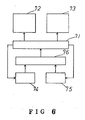
- FIG. 6 is a block diagram illustrating a configuration of another embodiment of the present invention.
- Selecting means 71 is intended to select analysing means 72 of a control code system A or analysing means 73 of a control code system B on the basis of compared results given by comparison means 76.
- the means 71 to 73 correspond with the judging unit 2 and control units 3 and 4 of Figure 1.
- the selecting means 71 selects one of the analysing means, say 72, the number of repetitions of the selection of the means 72 is written into A storage means 74. Likewise, if the means 73 is selected, this number is written into B storage means 75. Both of the A and B storage means 74 and 75 are of non-volatile type. If the power supply of the entire system is shut off, the data as to the number of repetitions which are stored in the storage means 74 and 75 can be held.
- the comparison means 76 compares the contents of the A and B storage means 74 and 75 and judges whether the control code system A or B has been selected more frequently.
- Control programs executed by the CPU incorporated into the unillustrated printer correspond to the selecting means 71, the analysing means 72 and 73 and the comparing means 76.
- the comparison means 76 When switching on the power supply or inputting an initialisation signal, the comparison means 76 reads the contents of the A and B storage means 74 and 75 and compares the magnitudes thereof. Subsequently, the comparison means 76 imparts to the selecting means 71 the information indicating whether the A or B storage means has the maximum content. It is assumed that the A storage means has a larger content than that of the B storage means in this example.
- the selecting means 71 receives an output from the comparison means, and immediately makes effective the analysing means 72 of the control system A. The steps up to this point are to be carried out as a part of initialising process every time the power supply has been switched on.
- selecting means 71 makes a judgement as to the working control code system.
- the result of its judgement is classified into the following three types:
- the selecting means 71 increases the content of the storage means 74 by 1 and makes effective the analysing means 72 of the control code system A.
- the analysing means 72 processes the input data transferred from an outside host in conformity with regulations of the control code system A.
- the selecting means 71 permits the control code system to remain effective, which exhibits the highest degree of frequency of use in the past, without changing the analysing means selected so far.
- the operation reverts to (a), (b), and (c). If the judgement regarding the control code system is made, the selecting means 71 increases the content of the relevant storage means and makes the relevant analysing means effective. If not, the analysing means remains effective as it is. Such steps are repeated.
- control code systems A and B there have been exemplified a comparison between the control code systems A and B. However, any one of three or more control code systems may be selected.
- the described embodiments feature a plurality of printing control units responsive to the character codes and the control codes from a variety of host units; the data transferred from the host units is de-coded; and one printing control unit is selected.
Landscapes
- Engineering & Computer Science (AREA)
- Theoretical Computer Science (AREA)
- Physics & Mathematics (AREA)
- General Engineering & Computer Science (AREA)
- General Physics & Mathematics (AREA)
- Audiology, Speech & Language Pathology (AREA)
- Computational Linguistics (AREA)
- General Health & Medical Sciences (AREA)
- Health & Medical Sciences (AREA)
- Artificial Intelligence (AREA)
- Probability & Statistics with Applications (AREA)
- Computer Hardware Design (AREA)
- Accessory Devices And Overall Control Thereof (AREA)
- Record Information Processing For Printing (AREA)
Claims (8)
- Einrichtung zum Erzeugen von Ausgabedaten für einen Druckvorgang in Antwort auf Eingabedaten, wie z.B. Zeichencodes und Steuercodes, welche von einer Vorrichtung empfangen werden, wobei die Einrichtung Eingabedatenspeichermittel (1, 21) zum Speichern von Daten umfaßt, welche von der Vorrichtung empfangen werden, sowie ein Umwandlungsmittel (3, 4, 23, 24, 25, 72, 73) zum Umwandeln der Codes in den Eingabedaten in Codes für den Druckvorgang auf der Basis, daß die Codes in den Eingabedaten von einer speziellen Codegruppe sind,
dadurch gekennzeichnet
daß ein Beurteilungsmittel (2, 22, 71) vorgesehen ist zum Bestimmen des Ausmaßes, in welchem die Eingabedaten mit der Syntax einer Mehrzahl bekannter Codegruppen übereinstimmen, um zu beurteilen, zu welcher der Codegruppen die Eingabedaten gehören, und daß das Umwandlungsmittel die Codes der Eingabedaten auf der Basis umwandelt, daß sie von der Gruppe sind, zu welcher sie durch das Beurteilungsmittel als zugehörig beurteilt worden sind. - Einrichtung nach Anspruch 1,
dadurch gekennzeichnet,
daß das Umwandlungsmittel (3, 4, 23, 24, 25, 72, 73) eine Mehrzahl von Drucksteuereinheiten umfaßt, von welchen jede auf eine jeweilige der bekannten Codegruppen anspricht, um Ausgabedaten für den Druckvorgang zu erzeugen, wobei die Eingabedaten an eine der Drucksteuereinheiten angelegt werden, welche danach ausgewählt ist, zu welcher der Codegruppen die Eingabedaten durch das Beurteilungsmittel (2, 22, 71) als zugehörig beurteilt sind. - Einrichtung nach Anspruch 1 oder 2,
dadurch gekennzeichnet,
daß das Beurteilungsmittel das Ausmaß bestimmt, in welchem die Eingabedaten mit der Syntax von jeder der Mehrzahl von Codegruppen übereinstimmen, indem für jede der bekannten Codegruppen ein Gesamtwert (ΣP) berechnet wird, wobei der Gesamtwert durch inkrementelles Aufwärtszählen desselben berechnet wird, wenn ein Steuercode in den Eingabedaten mit der Syntax eines Codes in der bekannten Codegruppe übereinstimmt, wobei das Inkrement ein erster Betrag ist, wenn der Steuercode in den Eingabedaten eine Mehrzahl von Bytes und ein Argument mit einem kleinen Bereich aufweist, ein zweiter Betrag ist, wenn der Steuercode in den Eingabedaten eine Mehrzahl von Bytes und ein Argument aufweist, welches alle möglichen Werten des Datenelements abdeckt, und ein dritter Betrag ist, wenn der Steuercode in den Eingabedaten ein oder zwei Bytes und kein Argument aufweist, wobei der erste Betrag größer ist als der zweite Betrag und der zweite Betrag größer ist als der dritte Betrag, und durch Berechnen eines Maximalwertes (ΣPmax) für jede der bekannten Codegruppen, wobei der Maximalwert berechnet wird durch inkrementelles Aufwärtszählen desselben für jeden Steuercode in den Eingabedaten, wobei das Inkrement ein erster Betrag ist, wenn der Steuercode in den Eingabedaten eine Mehrzahl von Bytes und ein Argument mit einem kleinen Bereich aufweist, ein zweiter Betrag ist, wenn der Steuercode in den Eingabedaten eine Mehrzahl von Bytes und ein Argument aufweist, welche alle möglichen Werte des Datenelements abdeckt, und ein dritter Betrag ist, wenn der Steuercode in den Eingabedaten ein oder zwei Bytes und kein Argument aufweist, wobei das Ausmaß, in welchem die Eingabedaten mit der Syntax von jeder der Mehrzahl bekannter Codegruppen übereinstimmt, durch Dividieren des Gesamtwertes (ΣP) durch den Maximalwert (ΣPmax) bestimmt wird. - Einrichtung nach einem der vorhergehenden Ansprüche,
dadurch gekennzeichnet,
daß sie ein Speichermittel (74, 75) zum Speichern eines Wertes umfaßt, welcher der Anzahl an Wiederholungen entspricht, mit welcher beurteilt wird, daß die Eingabedaten zu jeder der bekannten Codegruppen gehört, und daß das Umwandlungsmittel die Codes der Eingabedaten auf der Basis umwandelt, daß sie von der Gruppe sind, welche den höchsten in dem Speichermittel gespeicherten Wert aufweist, wenn das Beurteilungsmittel nicht bestimmen kann, zu welcher Gruppe die Eingabedaten gehören. - Kombination einer Einrichtung nach einem der vorhergehenden Ansprüche mit einem Drucker, welcher den Druckvorgang durchführt.
- Verfahren zum Erzeugen von Ausgabedaten für einen Druckvorgang in Antwort auf Eingabedaten, wie z.B. Zeichencodes und Steuercodes, welche von einer Vorrichtung empfangen werden, wobei das Verfahren umfaßt: das Speichern von Eingabedaten, welche von der Vorrichtung empfangen werden, und das Umwandeln von Codes in den Eingabedaten in Codes für den Druckvorgang auf der Basis, daß die Codes in den Eingabedaten von einer bestimmten Codegruppe sind,
dadurch gekennzeichnet,
daß das Ausmaß, in welchem die Eingabedaten mit der Syntax einer Mehrzahl bekannter Codegruppen übereinstimmen, bestimmt wird und dazu verwendet wird, zu beurteilen, zu welcher der bekannten Codegruppen die Eingabedaten gehören, und daß die Codes der Eingabedaten auf der Basis umgewandelt werden, daß sie von der Gruppe sind, zu welcher sie als zugehörig beurteilt werden. - Verfahren nach Anspruch 6,
dadurch gekennzeichnet,
daß das Ausmaß, in welchem die Eingabedaten mit der Syntax von jeder der Mehrzahl von bekannten Codegruppen übereinstimmt, durch Berechnen eines Gesamtwertes (ΣP) für jede der bekannten Codegruppen bestimmt wird, wobei der Gesamtwert durch inkrementelles Aufwärtszählen desselben berechnet wird, wenn ein Steuercode in den Eingabedaten mit der Syntax eines Codes in der bekannten Gruppe übereinstimmt, wobei das Inkrement ein erster Betrag ist, wenn der Steuercode in den Eingabedaten eine Mehrzahl von Bytes und ein Argument mit einem kleinen Bereich aufweist, ein zweiter Betrag ist, wenn der Steuercode in den Eingabedaten eine Mehrzahl von Bytes und ein Argument aufweist, welches alle möglichen Werte des Datenelements abdeckt, und ein dritter Betrag ist, wenn der Steuercode in den Eingabedaten ein oder zwei Bytes und kein Argument aufweist, wobei der erste Betrag größer ist als der zweite Betrag und der zweite Betrag größer ist als der dritte Betrag, und durch Berechnen eines Maximalwertes (ΣPmax) für jede der bekannten Codegruppen, wobei der Maximalwert durch inkrementelles Aufwärtszählen desselben für jeden Steuercode in den Eingabedaten berechnet wird, wobei das Inkrement ein erster Betrag ist, wenn der Steuercode in den Eingabedaten eine Mehrzahl von Bytes und ein Argument mit einem kleinen Bereich aufweist, ein zweiter Betrag ist, wenn der Steuercode in den Eingabedaten eine Mehrzahl von Bytes und ein Argument aufweist, welches alle möglichen Werte des Datenelements abdeckt, und ein dritter Betrag ist, wenn der Steuercode in den Eingabedaten ein oder zwei Bytes und kein Argument aufweist, wobei das Ausmaß, in welchem die Eingabedaten mit der Syntax von jeder der Mehrzahl bekannter Codegruppen übereinstimmt, durch Dividieren des Gesamtwertes (ΣP) durch den Maximalwert (ΣPmax) bestimmt wird. - Verfahren nach Anspruch 6 oder 7,
dadurch gekennzeichnet,
daß ein Wert, welcher der Anzahl an Wiederholungen entspricht, mit welcher die Eingabedaten als zu jeder der Codegruppen gehörend beurteilt wird, gespeichert wird, und daß die Codes der Eingabedaten auf der Basis umgewandelt werden, daß sie von der Gruppe sind, welche den höchsten gespeicherten Wert aufweist, wenn die Gruppe, zu welcher die Eingabedaten gehören, nicht bestimmt werden kann.
Applications Claiming Priority (4)
| Application Number | Priority Date | Filing Date | Title |
|---|---|---|---|
| JP64192/88 | 1988-03-17 | ||
| JP63064192A JP2985174B2 (ja) | 1987-03-17 | 1988-03-17 | 印刷装置 |
| JP63117416A JP2580708B2 (ja) | 1988-05-13 | 1988-05-13 | プリンタ |
| JP117416/88 | 1988-05-13 |
Publications (3)
| Publication Number | Publication Date |
|---|---|
| EP0332779A2 EP0332779A2 (de) | 1989-09-20 |
| EP0332779A3 EP0332779A3 (de) | 1992-10-21 |
| EP0332779B1 true EP0332779B1 (de) | 1995-07-12 |
Family
ID=26405320
Family Applications (1)
| Application Number | Title | Priority Date | Filing Date |
|---|---|---|---|
| EP88310906A Expired - Lifetime EP0332779B1 (de) | 1988-03-17 | 1988-11-18 | Vorrichtung und Verfahren zur Erzeugung von Daten für einen Druckvorgang, und ein Drucker, in Kombination mit der Vorrichtung, zur Ausführung des Druckvorganges |
Country Status (6)
| Country | Link |
|---|---|
| US (1) | US4992957A (de) |
| EP (1) | EP0332779B1 (de) |
| KR (1) | KR930009742B1 (de) |
| CN (1) | CN1017663B (de) |
| DE (1) | DE3854154T2 (de) |
| HK (1) | HK108496A (de) |
Cited By (1)
| Publication number | Priority date | Publication date | Assignee | Title |
|---|---|---|---|---|
| DE102020123341A1 (de) | 2019-11-30 | 2021-07-15 | Lars Jansen | Waffenkoffer zum Transport auf zumindest einem Sitz eines Fahrzeugs |
Families Citing this family (38)
| Publication number | Priority date | Publication date | Assignee | Title |
|---|---|---|---|---|
| US5819014A (en) * | 1990-04-06 | 1998-10-06 | Digital Equipment Corporation | Parallel distributed printer controller architecture |
| US5303336A (en) * | 1990-05-14 | 1994-04-12 | Hitachi, Ltd. | Printing system including print server |
| US5293466A (en) * | 1990-08-03 | 1994-03-08 | Qms, Inc. | Method and apparatus for selecting interpreter for printer command language based upon sample of print job transmitted to printer |
| US5165014A (en) * | 1990-09-12 | 1992-11-17 | Hewlett-Packard Company | Method and system for matching the software command language of a computer with the printer language of a printer |
| EP0477947B1 (de) * | 1990-09-28 | 1998-07-15 | Hewlett-Packard Company | Schalter zur gemeinsamen Benutzung eines Peripheriegeräts |
| US5280585A (en) * | 1990-09-28 | 1994-01-18 | Hewlett-Packard Company | Device sharing system using PCL macros |
| DE69233395T2 (de) * | 1991-03-12 | 2005-07-21 | Canon K.K. | Verfahren und Anordnung zur Datenausgabe |
| US5568594A (en) * | 1991-04-08 | 1996-10-22 | Kabushiki Kaisha Toshiba | Image forming apparatus with improved ability to emulate other image forming apparatuses |
| JP2661416B2 (ja) * | 1991-06-29 | 1997-10-08 | ブラザー工業株式会社 | 印字システム |
| JP3084807B2 (ja) * | 1991-07-10 | 2000-09-04 | ブラザー工業株式会社 | 印字装置 |
| US5668936A (en) * | 1991-09-25 | 1997-09-16 | Mita Industrial Co., Ltd. | Printer for exclusively selecting a host apparatus and a command system for use with the selected host apparatus |
| JP2875670B2 (ja) * | 1991-12-02 | 1999-03-31 | キヤノン株式会社 | 出力制御装置およびその出力制御方法 |
| JP2821296B2 (ja) * | 1991-12-06 | 1998-11-05 | キヤノン株式会社 | 印刷方法及び装置 |
| US5222200A (en) * | 1992-01-08 | 1993-06-22 | Lexmark International, Inc. | Automatic printer data stream language determination |
| CN1055553C (zh) * | 1992-01-24 | 2000-08-16 | 惠普公司 | 外围设备的语言识别系统和方法 |
| US5392419A (en) * | 1992-01-24 | 1995-02-21 | Hewlett-Packard Company | Language identification system and method for a peripheral unit |
| JP2830884B2 (ja) * | 1992-02-06 | 1998-12-02 | 日本電気株式会社 | 多重文字コードセットの入出力変換方式 |
| JP2958181B2 (ja) * | 1992-02-14 | 1999-10-06 | キヤノン株式会社 | 印刷装置 |
| JP2956343B2 (ja) * | 1992-03-13 | 1999-10-04 | ブラザー工業株式会社 | 印字装置の制御装置 |
| JP2871275B2 (ja) * | 1992-03-30 | 1999-03-17 | キヤノン株式会社 | 印刷制御装置及び該装置におけるエミュレーションプログラム選択方法 |
| EP0571145B1 (de) * | 1992-05-18 | 1999-10-13 | Canon Kabushiki Kaisha | Vorrichtung zur Übersetzung von Druckersteurungssprachen |
| JP2860204B2 (ja) * | 1992-05-18 | 1999-02-24 | キヤノン株式会社 | 出力装置及び当該装置における解釈プログラムの選択方法 |
| JP2839119B2 (ja) * | 1992-05-18 | 1998-12-16 | キヤノン株式会社 | 文字処理装置及び方法 |
| JP2862441B2 (ja) * | 1992-07-09 | 1999-03-03 | キヤノン株式会社 | 出力制御装置及び方法 |
| JP2871960B2 (ja) * | 1992-07-23 | 1999-03-17 | キヤノン株式会社 | 印刷方法及び装置 |
| EP0585523B1 (de) * | 1992-09-03 | 1998-12-09 | Hewlett-Packard Company | Automatische Sprachgrenzerkennung für ein Peripheriegerät, das eine Vielzahl von Steuersprachen unterstützt |
| JP3165268B2 (ja) * | 1992-10-30 | 2001-05-14 | キヤノン株式会社 | 印刷情報処理方法および装置 |
| US6044407A (en) * | 1992-11-13 | 2000-03-28 | British Telecommunications Public Limited Company | Interface for translating an information message from one protocol to another |
| JP2871370B2 (ja) * | 1993-01-20 | 1999-03-17 | キヤノン株式会社 | 出力制御方法及び装置 |
| EP0691056B2 (de) * | 1993-03-26 | 2008-06-11 | Cisco Technology, Inc. | Allgemeines modell von verwalteten objekten für den lan-bereich |
| KR0157847B1 (ko) * | 1993-04-07 | 1999-05-15 | 미따라이 하지메 | 정보 출력 장치 및 정보 출력 방법 |
| US5402527A (en) * | 1993-04-23 | 1995-03-28 | Xerox Corporation | Apparatus and method for determining the page description language in which a print job is written |
| JP3201141B2 (ja) * | 1994-06-02 | 2001-08-20 | セイコーエプソン株式会社 | データ受信方式 |
| US6002843A (en) * | 1994-06-15 | 1999-12-14 | Canon Kabushiki Kaisha | Printing apparatus and its control method |
| US6597465B1 (en) | 1994-08-09 | 2003-07-22 | Intermec Ip Corp. | Automatic mode detection and conversion system for printers and tag interrogators |
| US5828817A (en) * | 1995-06-29 | 1998-10-27 | Digital Equipment Corporation | Neural network recognizer for PDLs |
| JPH09198170A (ja) | 1996-01-16 | 1997-07-31 | Canon Inc | 電子機器 |
| US5784544A (en) * | 1996-08-30 | 1998-07-21 | International Business Machines Corporation | Method and system for determining the data type of a stream of data |
Family Cites Families (6)
| Publication number | Priority date | Publication date | Assignee | Title |
|---|---|---|---|---|
| JPS58154079A (ja) * | 1982-03-05 | 1983-09-13 | Hitachi Koki Co Ltd | 活字配列デ−タ編集装置 |
| US4594674A (en) * | 1983-02-18 | 1986-06-10 | International Business Machines Corporation | Generating and storing electronic fonts |
| JPS60252940A (ja) * | 1984-05-29 | 1985-12-13 | Fujitsu Ltd | プリンタ制御処理方式 |
| JPH0769772B2 (ja) * | 1984-07-03 | 1995-07-31 | 株式会社日立製作所 | プリンタシステム及びプリンタシステムのプリンタ機能指定方法 |
| US4679153A (en) * | 1985-04-26 | 1987-07-07 | R. R. Donnelley & Sons Company | Printing systems for typesetter emulation |
| JPH0688432B2 (ja) * | 1986-04-25 | 1994-11-09 | 三菱電機株式会社 | 漢字プリンタ制御装置 |
-
1988
- 1988-11-17 US US07/272,283 patent/US4992957A/en not_active Expired - Lifetime
- 1988-11-17 KR KR1019880015107A patent/KR930009742B1/ko not_active Expired - Lifetime
- 1988-11-18 EP EP88310906A patent/EP0332779B1/de not_active Expired - Lifetime
- 1988-11-18 DE DE3854154T patent/DE3854154T2/de not_active Expired - Lifetime
- 1988-11-19 CN CN88109191A patent/CN1017663B/zh not_active Expired
-
1996
- 1996-06-27 HK HK108496A patent/HK108496A/en not_active IP Right Cessation
Cited By (1)
| Publication number | Priority date | Publication date | Assignee | Title |
|---|---|---|---|---|
| DE102020123341A1 (de) | 2019-11-30 | 2021-07-15 | Lars Jansen | Waffenkoffer zum Transport auf zumindest einem Sitz eines Fahrzeugs |
Also Published As
| Publication number | Publication date |
|---|---|
| HK108496A (en) | 1996-07-05 |
| DE3854154D1 (de) | 1995-08-17 |
| KR930009742B1 (ko) | 1993-10-09 |
| CN1017663B (zh) | 1992-07-29 |
| KR890014269A (ko) | 1989-10-23 |
| DE3854154T2 (de) | 1995-11-09 |
| EP0332779A2 (de) | 1989-09-20 |
| CN1036168A (zh) | 1989-10-11 |
| EP0332779A3 (de) | 1992-10-21 |
| US4992957A (en) | 1991-02-12 |
Similar Documents
| Publication | Publication Date | Title |
|---|---|---|
| EP0332779A2 (de) | Vorrichtung und Verfahren zur Erzeugung von Daten für einen Druckvorgang, und ein Drucker, in Kombination mit der Vorrichtung, zur Ausführung des Druckvorganges | |
| JP3485588B2 (ja) | 周辺装置のための言語識別方法 | |
| US4896148A (en) | Display apparatus | |
| EP0469974B1 (de) | Drucker, der verschiedene Druckersteuerungssprachen auswertet | |
| EP0326275A2 (de) | Rechnersystem, das mit vielfachen Anzeigearten arbeiten kann | |
| KR0167617B1 (ko) | 출력 제어 장치 및 방법 | |
| US4359286A (en) | Character set expansion | |
| EP0478304B1 (de) | Zeichenausgabegerät | |
| US5469373A (en) | Printing apparatus and method that discriminates which analyzer should analyze information | |
| US5381552A (en) | Programmable system for prioritizing and collecting central processor unit interrupts | |
| EP0357383A2 (de) | Ausgabegerät | |
| EP0513829B1 (de) | Prozessor und Verfahren für unscharfe Schlussfolgerung, und Verfahren und Anordnung zur Regelbestimmung | |
| US4827530A (en) | Method and apparatus for Korean character recognition from Korean alphabet row | |
| EP0571145B1 (de) | Vorrichtung zur Übersetzung von Druckersteurungssprachen | |
| KR970010375B1 (ko) | 밴드 오버런 에러를 방지하는 페이지 프린터의 밴드 프린팅방법 | |
| US5745663A (en) | Data receiving system | |
| EP0198255B1 (de) | Geteilter Druck von Punktmustern mit hoher Dichte | |
| US6396591B1 (en) | Method of printing with a host-based printer using a rudimentary internal font without assistance from the host and with minimal printer memory | |
| EP0687972B1 (de) | Druckersystem und Verfahren zur Anzeige der erforderlichen Druckzeit des Druckers | |
| KR100270267B1 (ko) | 인쇄 등급 제어 장치 및 방법 | |
| US6720970B2 (en) | Image drawing apparatus, image drawing method and memory medium | |
| US5473743A (en) | Character generator with selectable conversion | |
| GB2165071A (en) | Device for the inputting of character data | |
| EP0596752A1 (de) | Datenverarbeitungseinrichtung zur Schaltung der Datenempfangsräte | |
| EP0531528B1 (de) | Zeichenausgabe-steuerverfahren und -vorrichtung für ein datenendgerät |
Legal Events
| Date | Code | Title | Description |
|---|---|---|---|
| PUAI | Public reference made under article 153(3) epc to a published international application that has entered the european phase |
Free format text: ORIGINAL CODE: 0009012 |
|
| AK | Designated contracting states |
Kind code of ref document: A2 Designated state(s): DE FR GB |
|
| PUAL | Search report despatched |
Free format text: ORIGINAL CODE: 0009013 |
|
| AK | Designated contracting states |
Kind code of ref document: A3 Designated state(s): DE FR GB |
|
| 17P | Request for examination filed |
Effective date: 19930419 |
|
| 17Q | First examination report despatched |
Effective date: 19940309 |
|
| GRAA | (expected) grant |
Free format text: ORIGINAL CODE: 0009210 |
|
| AK | Designated contracting states |
Kind code of ref document: B1 Designated state(s): DE FR GB |
|
| REF | Corresponds to: |
Ref document number: 3854154 Country of ref document: DE Date of ref document: 19950817 |
|
| ET | Fr: translation filed | ||
| PLBE | No opposition filed within time limit |
Free format text: ORIGINAL CODE: 0009261 |
|
| STAA | Information on the status of an ep patent application or granted ep patent |
Free format text: STATUS: NO OPPOSITION FILED WITHIN TIME LIMIT |
|
| 26N | No opposition filed | ||
| REG | Reference to a national code |
Ref country code: GB Ref legal event code: IF02 |
|
| PGFP | Annual fee paid to national office [announced via postgrant information from national office to epo] |
Ref country code: DE Payment date: 20071115 Year of fee payment: 20 |
|
| PGFP | Annual fee paid to national office [announced via postgrant information from national office to epo] |
Ref country code: FR Payment date: 20071108 Year of fee payment: 20 Ref country code: GB Payment date: 20071114 Year of fee payment: 20 |
|
| REG | Reference to a national code |
Ref country code: GB Ref legal event code: PE20 Expiry date: 20081117 |
|
| PG25 | Lapsed in a contracting state [announced via postgrant information from national office to epo] |
Ref country code: GB Free format text: LAPSE BECAUSE OF EXPIRATION OF PROTECTION Effective date: 20081117 |