EP0332452A1 - Automatische Synthesevorrichtung - Google Patents
Automatische Synthesevorrichtung Download PDFInfo
- Publication number
- EP0332452A1 EP0332452A1 EP19890302370 EP89302370A EP0332452A1 EP 0332452 A1 EP0332452 A1 EP 0332452A1 EP 19890302370 EP19890302370 EP 19890302370 EP 89302370 A EP89302370 A EP 89302370A EP 0332452 A1 EP0332452 A1 EP 0332452A1
- Authority
- EP
- European Patent Office
- Prior art keywords
- liquid
- unit
- reaction
- transporting
- flow lines
- Prior art date
- Legal status (The legal status is an assumption and is not a legal conclusion. Google has not performed a legal analysis and makes no representation as to the accuracy of the status listed.)
- Granted
Links
- 230000002194 synthesizing effect Effects 0.000 title claims abstract description 21
- 238000006243 chemical reaction Methods 0.000 claims abstract description 275
- 239000007788 liquid Substances 0.000 claims abstract description 136
- 239000003153 chemical reaction reagent Substances 0.000 claims abstract description 94
- 239000002994 raw material Substances 0.000 claims abstract description 88
- 239000002904 solvent Substances 0.000 claims abstract description 88
- 238000000746 purification Methods 0.000 claims abstract description 36
- 239000012295 chemical reaction liquid Substances 0.000 claims abstract description 22
- 238000004108 freeze drying Methods 0.000 claims abstract description 20
- 239000000047 product Substances 0.000 claims abstract description 18
- 238000000926 separation method Methods 0.000 claims abstract description 14
- 230000000712 assembly Effects 0.000 claims abstract description 13
- 238000000429 assembly Methods 0.000 claims abstract description 13
- 239000012264 purified product Substances 0.000 claims abstract description 12
- 238000011002 quantification Methods 0.000 claims abstract description 3
- 238000004128 high performance liquid chromatography Methods 0.000 claims description 62
- 238000010438 heat treatment Methods 0.000 claims description 32
- 239000002826 coolant Substances 0.000 claims description 26
- 238000001035 drying Methods 0.000 claims description 26
- 238000003756 stirring Methods 0.000 claims description 22
- 239000011541 reaction mixture Substances 0.000 claims description 21
- 238000000605 extraction Methods 0.000 claims description 15
- 238000012546 transfer Methods 0.000 claims description 14
- 238000012544 monitoring process Methods 0.000 claims description 11
- 238000001816 cooling Methods 0.000 claims description 10
- 239000002699 waste material Substances 0.000 claims description 9
- 239000007795 chemical reaction product Substances 0.000 claims description 7
- 238000010979 pH adjustment Methods 0.000 claims description 7
- 238000005259 measurement Methods 0.000 claims description 6
- 238000004458 analytical method Methods 0.000 claims description 5
- 239000003960 organic solvent Substances 0.000 claims description 4
- 238000012545 processing Methods 0.000 claims description 4
- 239000002253 acid Substances 0.000 claims description 3
- 239000003513 alkali Substances 0.000 claims description 3
- 239000012141 concentrate Substances 0.000 claims description 3
- 230000032258 transport Effects 0.000 claims 10
- 238000012806 monitoring device Methods 0.000 claims 2
- 238000007599 discharging Methods 0.000 claims 1
- 238000002347 injection Methods 0.000 claims 1
- 239000007924 injection Substances 0.000 claims 1
- 239000007791 liquid phase Substances 0.000 claims 1
- 238000005070 sampling Methods 0.000 claims 1
- 238000005406 washing Methods 0.000 abstract description 8
- 102100027324 2-hydroxyacyl-CoA lyase 1 Human genes 0.000 abstract 1
- 101001009252 Homo sapiens 2-hydroxyacyl-CoA lyase 1 Proteins 0.000 abstract 1
- OKKJLVBELUTLKV-UHFFFAOYSA-N Methanol Chemical compound OC OKKJLVBELUTLKV-UHFFFAOYSA-N 0.000 description 54
- 101710118890 Photosystem II reaction center protein Ycf12 Proteins 0.000 description 43
- XEKOWRVHYACXOJ-UHFFFAOYSA-N Ethyl acetate Chemical class CCOC(C)=O XEKOWRVHYACXOJ-UHFFFAOYSA-N 0.000 description 25
- 239000000243 solution Substances 0.000 description 25
- 238000003860 storage Methods 0.000 description 20
- XLYOFNOQVPJJNP-UHFFFAOYSA-N water Substances O XLYOFNOQVPJJNP-UHFFFAOYSA-N 0.000 description 19
- 238000010586 diagram Methods 0.000 description 18
- 239000010410 layer Substances 0.000 description 18
- 238000000034 method Methods 0.000 description 17
- 238000003786 synthesis reaction Methods 0.000 description 14
- 230000015572 biosynthetic process Effects 0.000 description 12
- 239000012044 organic layer Substances 0.000 description 12
- 239000000203 mixture Substances 0.000 description 11
- 210000000188 diaphragm Anatomy 0.000 description 9
- 235000019439 ethyl acetate Nutrition 0.000 description 9
- HEDRZPFGACZZDS-UHFFFAOYSA-N Chloroform Chemical compound ClC(Cl)Cl HEDRZPFGACZZDS-UHFFFAOYSA-N 0.000 description 8
- 101150016011 RR11 gene Proteins 0.000 description 8
- 239000012467 final product Substances 0.000 description 8
- 102100038968 WAP four-disulfide core domain protein 1 Human genes 0.000 description 7
- 150000001875 compounds Chemical class 0.000 description 7
- 239000000256 polyoxyethylene sorbitan monolaurate Substances 0.000 description 7
- 230000009102 absorption Effects 0.000 description 6
- 238000010521 absorption reaction Methods 0.000 description 6
- 230000005587 bubbling Effects 0.000 description 6
- 238000002955 isolation Methods 0.000 description 6
- HEMHJVSKTPXQMS-UHFFFAOYSA-M sodium hydroxide Inorganic materials [OH-].[Na+] HEMHJVSKTPXQMS-UHFFFAOYSA-M 0.000 description 6
- 101100350459 Oryza sativa subsp. japonica RR26 gene Proteins 0.000 description 5
- 238000010276 construction Methods 0.000 description 5
- 230000000694 effects Effects 0.000 description 5
- XKRFYHLGVUSROY-UHFFFAOYSA-N Argon Chemical compound [Ar] XKRFYHLGVUSROY-UHFFFAOYSA-N 0.000 description 4
- IJGRMHOSHXDMSA-UHFFFAOYSA-N Atomic nitrogen Chemical compound N#N IJGRMHOSHXDMSA-UHFFFAOYSA-N 0.000 description 4
- RTZKZFJDLAIYFH-UHFFFAOYSA-N Diethyl ether Chemical compound CCOCC RTZKZFJDLAIYFH-UHFFFAOYSA-N 0.000 description 4
- 101150116266 RR24 gene Proteins 0.000 description 4
- PMZURENOXWZQFD-UHFFFAOYSA-L Sodium Sulfate Chemical compound [Na+].[Na+].[O-]S([O-])(=O)=O PMZURENOXWZQFD-UHFFFAOYSA-L 0.000 description 4
- 239000002274 desiccant Substances 0.000 description 4
- 238000001514 detection method Methods 0.000 description 4
- 238000000921 elemental analysis Methods 0.000 description 4
- 239000003480 eluent Substances 0.000 description 4
- BEOOHQFXGBMRKU-UHFFFAOYSA-N sodium cyanoborohydride Chemical compound [Na+].[B-]C#N BEOOHQFXGBMRKU-UHFFFAOYSA-N 0.000 description 4
- 125000001424 substituent group Chemical group 0.000 description 4
- 239000007832 Na2SO4 Substances 0.000 description 3
- 101100135117 Oryza sativa subsp. japonica RR13 gene Proteins 0.000 description 3
- 239000007864 aqueous solution Substances 0.000 description 3
- 239000000543 intermediate Substances 0.000 description 3
- 230000014759 maintenance of location Effects 0.000 description 3
- 239000000463 material Substances 0.000 description 3
- 229960005190 phenylalanine Drugs 0.000 description 3
- 239000000843 powder Substances 0.000 description 3
- 230000008569 process Effects 0.000 description 3
- 230000036647 reaction Effects 0.000 description 3
- 238000011160 research Methods 0.000 description 3
- 230000004044 response Effects 0.000 description 3
- 229910052938 sodium sulfate Inorganic materials 0.000 description 3
- 235000011152 sodium sulphate Nutrition 0.000 description 3
- 238000000638 solvent extraction Methods 0.000 description 3
- 239000000126 substance Substances 0.000 description 3
- LFQSCWFLJHTTHZ-UHFFFAOYSA-N Ethanol Chemical compound CCO LFQSCWFLJHTTHZ-UHFFFAOYSA-N 0.000 description 2
- 101100350458 Oryza sativa subsp. japonica RR25 gene Proteins 0.000 description 2
- 101150048609 RR21 gene Proteins 0.000 description 2
- 101150048251 RR23 gene Proteins 0.000 description 2
- DTQVDTLACAAQTR-UHFFFAOYSA-N Trifluoroacetic acid Chemical compound OC(=O)C(F)(F)F DTQVDTLACAAQTR-UHFFFAOYSA-N 0.000 description 2
- 230000003213 activating effect Effects 0.000 description 2
- 229910052786 argon Inorganic materials 0.000 description 2
- 230000008859 change Effects 0.000 description 2
- 229920001429 chelating resin Polymers 0.000 description 2
- 238000004587 chromatography analysis Methods 0.000 description 2
- 238000001704 evaporation Methods 0.000 description 2
- 230000008020 evaporation Effects 0.000 description 2
- 238000002474 experimental method Methods 0.000 description 2
- HHLFWLYXYJOTON-UHFFFAOYSA-N glyoxylic acid Chemical compound OC(=O)C=O HHLFWLYXYJOTON-UHFFFAOYSA-N 0.000 description 2
- 239000011261 inert gas Substances 0.000 description 2
- 238000004519 manufacturing process Methods 0.000 description 2
- 238000012986 modification Methods 0.000 description 2
- 230000004048 modification Effects 0.000 description 2
- 229910052757 nitrogen Inorganic materials 0.000 description 2
- 238000011017 operating method Methods 0.000 description 2
- 238000004810 partition chromatography Methods 0.000 description 2
- 238000002953 preparative HPLC Methods 0.000 description 2
- 101100313763 Arabidopsis thaliana TIM22-2 gene Proteins 0.000 description 1
- 101100203596 Caenorhabditis elegans sol-1 gene Proteins 0.000 description 1
- QXNVGIXVLWOKEQ-UHFFFAOYSA-N Disodium Chemical class [Na][Na] QXNVGIXVLWOKEQ-UHFFFAOYSA-N 0.000 description 1
- 101001128431 Homo sapiens Myeloid-derived growth factor Proteins 0.000 description 1
- 102100031789 Myeloid-derived growth factor Human genes 0.000 description 1
- 101100135116 Oryza sativa subsp. japonica RR12 gene Proteins 0.000 description 1
- 101000600488 Pinus strobus Putative phosphoglycerate kinase Proteins 0.000 description 1
- 239000002202 Polyethylene glycol Substances 0.000 description 1
- 101150110620 RR22 gene Proteins 0.000 description 1
- MJENCSCLVWMJDU-MERQFXBCSA-N acetic acid;tert-butyl (2s)-2-amino-3-phenylpropanoate Chemical compound CC(O)=O.CC(C)(C)OC(=O)[C@@H](N)CC1=CC=CC=C1 MJENCSCLVWMJDU-MERQFXBCSA-N 0.000 description 1
- PRAMATAGVIEQRO-WSZWBAFRSA-N acetic acid;tert-butyl (2s,3s)-2-amino-3-methylpentanoate Chemical compound CC(O)=O.CC[C@H](C)[C@H](N)C(=O)OC(C)(C)C PRAMATAGVIEQRO-WSZWBAFRSA-N 0.000 description 1
- 239000003929 acidic solution Substances 0.000 description 1
- 230000002378 acidificating effect Effects 0.000 description 1
- 230000009471 action Effects 0.000 description 1
- 150000003862 amino acid derivatives Chemical class 0.000 description 1
- 239000003637 basic solution Substances 0.000 description 1
- 238000011021 bench scale process Methods 0.000 description 1
- 230000004071 biological effect Effects 0.000 description 1
- 238000004364 calculation method Methods 0.000 description 1
- 239000003054 catalyst Substances 0.000 description 1
- 239000007810 chemical reaction solvent Substances 0.000 description 1
- 230000002301 combined effect Effects 0.000 description 1
- 238000004891 communication Methods 0.000 description 1
- 239000000498 cooling water Substances 0.000 description 1
- 238000013461 design Methods 0.000 description 1
- 238000011161 development Methods 0.000 description 1
- 238000001962 electrophoresis Methods 0.000 description 1
- 238000005516 engineering process Methods 0.000 description 1
- 239000012530 fluid Substances 0.000 description 1
- 230000006870 function Effects 0.000 description 1
- 239000011521 glass Substances 0.000 description 1
- 239000001307 helium Substances 0.000 description 1
- 229910052734 helium Inorganic materials 0.000 description 1
- SWQJXJOGLNCZEY-UHFFFAOYSA-N helium atom Chemical compound [He] SWQJXJOGLNCZEY-UHFFFAOYSA-N 0.000 description 1
- VEXZGXHMUGYJMC-UHFFFAOYSA-N hydrochloric acid Substances Cl VEXZGXHMUGYJMC-UHFFFAOYSA-N 0.000 description 1
- 230000000977 initiatory effect Effects 0.000 description 1
- 238000003780 insertion Methods 0.000 description 1
- 230000037431 insertion Effects 0.000 description 1
- 150000004715 keto acids Chemical class 0.000 description 1
- 230000005389 magnetism Effects 0.000 description 1
- 229940057952 methanol Drugs 0.000 description 1
- 238000003541 multi-stage reaction Methods 0.000 description 1
- 238000005457 optimization Methods 0.000 description 1
- 238000005192 partition Methods 0.000 description 1
- 239000000825 pharmaceutical preparation Substances 0.000 description 1
- 229940127557 pharmaceutical product Drugs 0.000 description 1
- 238000011020 pilot scale process Methods 0.000 description 1
- 229920001223 polyethylene glycol Polymers 0.000 description 1
- 238000005086 pumping Methods 0.000 description 1
- 238000010926 purge Methods 0.000 description 1
- 238000001953 recrystallisation Methods 0.000 description 1
- BWAUQTFFVCLSOS-UHFFFAOYSA-N sodiosodium hydrate Chemical compound O.[Na].[Na] BWAUQTFFVCLSOS-UHFFFAOYSA-N 0.000 description 1
- WDCARDDLMCHULC-UHFFFAOYSA-M sodium;2-oxohexanoate Chemical compound [Na+].CCCCC(=O)C([O-])=O WDCARDDLMCHULC-UHFFFAOYSA-M 0.000 description 1
- 239000002912 waste gas Substances 0.000 description 1
Images


Classifications
-
- B—PERFORMING OPERATIONS; TRANSPORTING
- B01—PHYSICAL OR CHEMICAL PROCESSES OR APPARATUS IN GENERAL
- B01J—CHEMICAL OR PHYSICAL PROCESSES, e.g. CATALYSIS OR COLLOID CHEMISTRY; THEIR RELEVANT APPARATUS
- B01J19/00—Chemical, physical or physico-chemical processes in general; Their relevant apparatus
- B01J19/0006—Controlling or regulating processes
- B01J19/004—Multifunctional apparatus for automatic manufacturing of various chemical products
-
- C—CHEMISTRY; METALLURGY
- C07—ORGANIC CHEMISTRY
- C07C—ACYCLIC OR CARBOCYCLIC COMPOUNDS
- C07C227/00—Preparation of compounds containing amino and carboxyl groups bound to the same carbon skeleton
- C07C227/04—Formation of amino groups in compounds containing carboxyl groups
- C07C227/06—Formation of amino groups in compounds containing carboxyl groups by addition or substitution reactions, without increasing the number of carbon atoms in the carbon skeleton of the acid
- C07C227/08—Formation of amino groups in compounds containing carboxyl groups by addition or substitution reactions, without increasing the number of carbon atoms in the carbon skeleton of the acid by reaction of ammonia or amines with acids containing functional groups
-
- C—CHEMISTRY; METALLURGY
- C07—ORGANIC CHEMISTRY
- C07C—ACYCLIC OR CARBOCYCLIC COMPOUNDS
- C07C227/00—Preparation of compounds containing amino and carboxyl groups bound to the same carbon skeleton
- C07C227/14—Preparation of compounds containing amino and carboxyl groups bound to the same carbon skeleton from compounds containing already amino and carboxyl groups or derivatives thereof
- C07C227/18—Preparation of compounds containing amino and carboxyl groups bound to the same carbon skeleton from compounds containing already amino and carboxyl groups or derivatives thereof by reactions involving amino or carboxyl groups, e.g. hydrolysis of esters or amides, by formation of halides, salts or esters
-
- B—PERFORMING OPERATIONS; TRANSPORTING
- B01—PHYSICAL OR CHEMICAL PROCESSES OR APPARATUS IN GENERAL
- B01J—CHEMICAL OR PHYSICAL PROCESSES, e.g. CATALYSIS OR COLLOID CHEMISTRY; THEIR RELEVANT APPARATUS
- B01J2219/00—Chemical, physical or physico-chemical processes in general; Their relevant apparatus
- B01J2219/00002—Chemical plants
- B01J2219/00027—Process aspects
- B01J2219/00038—Processes in parallel
-
- Y—GENERAL TAGGING OF NEW TECHNOLOGICAL DEVELOPMENTS; GENERAL TAGGING OF CROSS-SECTIONAL TECHNOLOGIES SPANNING OVER SEVERAL SECTIONS OF THE IPC; TECHNICAL SUBJECTS COVERED BY FORMER USPC CROSS-REFERENCE ART COLLECTIONS [XRACs] AND DIGESTS
- Y10—TECHNICAL SUBJECTS COVERED BY FORMER USPC
- Y10S—TECHNICAL SUBJECTS COVERED BY FORMER USPC CROSS-REFERENCE ART COLLECTIONS [XRACs] AND DIGESTS
- Y10S203/00—Distillation: processes, separatory
- Y10S203/02—Laboratory distillation
-
- Y—GENERAL TAGGING OF NEW TECHNOLOGICAL DEVELOPMENTS; GENERAL TAGGING OF CROSS-SECTIONAL TECHNOLOGIES SPANNING OVER SEVERAL SECTIONS OF THE IPC; TECHNICAL SUBJECTS COVERED BY FORMER USPC CROSS-REFERENCE ART COLLECTIONS [XRACs] AND DIGESTS
- Y10—TECHNICAL SUBJECTS COVERED BY FORMER USPC
- Y10T—TECHNICAL SUBJECTS COVERED BY FORMER US CLASSIFICATION
- Y10T436/00—Chemistry: analytical and immunological testing
- Y10T436/12—Condition responsive control
-
- Y—GENERAL TAGGING OF NEW TECHNOLOGICAL DEVELOPMENTS; GENERAL TAGGING OF CROSS-SECTIONAL TECHNOLOGIES SPANNING OVER SEVERAL SECTIONS OF THE IPC; TECHNICAL SUBJECTS COVERED BY FORMER USPC CROSS-REFERENCE ART COLLECTIONS [XRACs] AND DIGESTS
- Y10—TECHNICAL SUBJECTS COVERED BY FORMER USPC
- Y10T—TECHNICAL SUBJECTS COVERED BY FORMER US CLASSIFICATION
- Y10T436/00—Chemistry: analytical and immunological testing
- Y10T436/25—Chemistry: analytical and immunological testing including sample preparation
- Y10T436/2575—Volumetric liquid transfer
Definitions
- the present invention generally relates to an automated synthesizing apparatus and, more particularly, a computer-assisted automated synthesizing apparatus for the automated synthesis of a plurality of derivatives of particular chemical composition such as the synthesis of substituted N-(carboxyalkyl)amino acids and their derivatives.
- the present invention has been developed with due regards paid to the foregoing prior art technology and has for its essential object to provide an apparatus capable of automatically synthesizing a relatively wide range of compounds and also of being used for isolation and purification of the compounds.
- the present invention provides an automated synthesizing apparatus which comprises a raw material, reagent and solvent supply unit, a reaction unit, a purification unit provided with a device such as, for example, HPLC (high performance liquid chromatography) or CPC (centrifugal partition chromatography), and a freeze-drying unit for freeze-drying the purified products supplied from the purification unit.
- a device such as, for example, HPLC (high performance liquid chromatography) or CPC (centrifugal partition chromatography)
- a freeze-drying unit for freeze-drying the purified products supplied from the purification unit.
- the raw material, reagent and solvent supply unit comprises one or a plurality of reservoirs for containing raw material, reagents and solvents; volumetric tubes equipped with a gas-liquid boundary sensors for the quantification of the raw material, reagents and solvents from the reservoirs; flow-lines for supplying the raw material, reagent and solvent from the reservoirs towards subsequent steps; and solenoid valve assemblies disposed on the respective flow-lines for selectively closing and opening such respective flow-lines.
- the reaction unit comprises a reaction flask device adapted to receive the raw material from the raw material, reagent and solvent supply unit; a separation funnel for extracting and washing a product which is transferred from the reaction flask device; a pH adjusting flask for adjusting acidity or basicity of the reaction liquid from the separation funnel; a plurality of reagent reservoirs disposed for adding a predetermined quantity of reagent to the reaction flask device, volumetric tubes and gas-liquid boundary sensors.
- an automated synthesizing apparatus comprises a supply unit which comprises a plurality of reservoirs containing raw material, reagents, solvents, pH adjusting liquid, etc., means for automatically supplying the said liquids from source baths to the reservoirs, volumetric tubes and sensors for quantifying the said liquids from the reservoirs, flow lines connecting the reservoirs to subsequent processing steps, and solenoid valves disposed on the flow lines for selectively opening and closing passages; a reaction unit which comprises the said plurality of reaction flasks and pH adjusting flasks, flow lines capable of allowing the liquids to be supplied from selected ones of the reservoirs of the supply unit, flow lines capable of allowing recirculation among the reaction flasks and between the reaction flasks and the pH adjusting flasks, an extraction/separation funnel and a drying tube circulatorily disposed among the flasks through flow lines, a monitoring HPLC for the analysis of a reaction liquid, which HPLC is connected with the reaction flas
- the apparatus comprises a services unit including a heating medium/cooling medium circulating unit for supplying a heating medium or a coolant for heating or cooling the reaction flask disposed in the above described unit, a wash-solvent supply unit for washing various components of the above described units and the flow-lines, and an exhaust/drainage unit for exhausting the above described wash-solvent and other wastes.
- a services unit including a heating medium/cooling medium circulating unit for supplying a heating medium or a coolant for heating or cooling the reaction flask disposed in the above described unit, a wash-solvent supply unit for washing various components of the above described units and the flow-lines, and an exhaust/drainage unit for exhausting the above described wash-solvent and other wastes.
- the reaction flask device is provided with a jacket provided at an outer periphery thereof for heating or cooling it and has a gap between the flask and the jacket for the circulation of the heating medium or the coolant.
- the flask is provided with stirrer blades for stirring the reaction liquid within the flask and has an opening defined at top thereof for connection with a pressure reducing means.
- a vessel which acts as a concentration sensor having an opening through which a thermocouple is inserted is fitted to the flask.
- the reaction flasks may have coolant tubes mounted thereabove in communication therewith so that vapor from the reaction flasks can be condensed with the resultant liquid being allowed to drop into the flasks.
- air may be introduced into the reaction flasks to bubble the liquid for the purpose of stirring and/or each of the reaction flasks may be surrounded by a respective oil bath provided with a heating means such as a heater.
- a filter may be provided in the vicinity of the drying tubes and valves and/or at portions of the flow lines from which the liquid or air is withdrawn.
- an extracting device is preferably provided with a temporary storage bottle for the temporary storage since the extraction is repeatedly carried out.
- an electrophoresis device in the purification unit, other than HPLC and CPC, an electrophoresis device, an centrifugal chromatography or a recrystallization device or a combination thereof can be employed in the practice of the present invention.
- arrangement may be preferably made that, while two purification devices such as HPLC and CPC are provided, the reaction liquid can be selectively or continuously supplied to HPLC and CPC.
- the automated synthesizing apparatus comprises a series of units including the raw material, reagent and solvent supply unit, the reaction unit, the purification unit and the freeze-drying unit and the services unit, all of those units being automatically controlled by the computer to efficiently produce many derivatives of one particular compound structure with no need of manual intervention.
- An automated synthesizing apparatus general strictlyly comprises a computer system and a synthesis system.
- the computer system comprises, as best shown in Fig. 1, a computer 1 and an interface 2, the said computer 1 being connected with CRT monitor 3 and a printer 4 while the interface 2 is connected to a main electric power source 5.
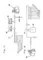
- the automated synthesizing apparatus shown in Fig. 1 comprises as shown in Fig. 2, a raw material, reagent and solvent supply unit 6, a reaction unit 7, a purification unit 8, a freeze-drying unit 9, a heating medium/cooling medium circulating unit 10, a wash-solvent supply unit 11 and an exhaust/drainage unit 12.
- a final product given by the automated synthesizing apparatus is directed mainly to a water-soluble product and the apparatus is so designed that various procedures takes place sequentially in one way in the order from the supply unit 6, the reaction unit 7, the purification unit 8 and the freeze-drying unit 9 to give a final product which is a powdered synthesized material.
- All of the above described hardware units 6 to 12 are connected, through the interface 2, in the computer 1 which forms a control unit so that all of these units can be controlled and operated according to a program stored in a disket of the computer 1.
- Each of service units such as the heating medium/cooling medium circulating unit 10, the wash-solvent supply unit 11 and the exhaust/drainage unit 12, the reaction unit 7 and the purification unit 8 can be controlled to accomplish the reaction and purification and isolation of a product 15 via the freeze-drying unit 9.
- the raw material, reagent and solvent supply unit 6 comprises two separate supply devices 20A and 20B from which different raw material is supplied in a different predetermined volume.
- the supply device 20A includes one or a plurality of, for example, seven, reservoirs RAI1to RA7 for containing raw material A such as, for example, amino acid derivatives, and the supply device 20B includes two reservoirs RK1 and RK2 for containing raw material B such as, for example, keto-acids.
- the raw material A is quantified to, for example, 5 ml and the raw material B is quantified to, for example, 10 ml, these predetermined quantities of the raw material A and B being supplied to a first reaction flask RF1 which forms a part of the subsequent reaction unit 7.
- the identical volume of these solution can be measured by repetition.
- the reservoirs RA1 to RA7 are connected to a common supply line L1-2 through respective supply lines L1-1, the said common supply line L1-2 being connected to the first reaction flask RF1.
- the supply lines L1-1 have respective solenoid valve assemblies SOL1-1 disposed thereon for selectively opening and closing such supply lines, and the common supply line L1-2 has a three-way solenoid valve assembly SOL1-2 disposed thereon.
- the three-way solenoid valve assembly SOL1-2 is connected with a line L1-3 having both of a 5 ml volumetric tube MT1 and a gas-liquid boundary sensor PS1 in the form of a photosensor disposed thereon and operable to supply the raw material A supplied from the reservoirs RA1 to RA7 to the line L1-3.
- the solenoid valve assembly SOL1-2 is activated to supply the quantified raw material A to the first reaction flask RF1 of the reaction unit 7.
- the supply device 20B is substantially similar to the supply device 20A.
- supply lines L1-4 connected respectively with the reservoirs RK1 and RK2 are connected with the first reaction flask RF1 through a common supply line L1-5.
- Solenoid valve assemblies SOL1-3 and SOL1-5 are disposed respectively on the supply lines L1-4 and the common supply line L1-5.
- the solenoid valve assembly SOL1-4 is connected with a line L1-6 having both of a 10 ml volumetric tube MT2 and a gas-liquid boundary sensor PS2 disposed thereon so that the raw material B can be quantified to 10 ml and can then be supplied to the first reaction flask RF1.
- All of the reservoirs RA1 to RA7, RK1 and RK2 and the volumetric tubes Mt1 and MT2 are adapted to be washed with water and methanol alternately directed thereto and, for this purpose, the lines L1-1 to L1-6 are connected with lines L1-7 to L1-9, connected with the wash-solvent supply unit 11, through a solenoid valve assembly SOL1-5 and a wash-solvent supply line L1-10. Also, for the purpose of exhausting the washing liquid to the exhaust/drainage unit 12, the above described lines are connected with exhaust lines L1-11 and L1-12 through a solenoid valve assembly SOL1-6. It is to be noted that all of the above described lines form part of a closed system.
- the reaction unit 7 comprises two series of reaction systems and one pH adjusting system. Namely, the reaction unit 7 comprises six reagent supply devices 21A to 21F, two reaction flask devices 22A and 22B, a separation funnel device 23 provided with a liquid-liquid boundary sensor LS, and a pH adjusting flask device 24 having one pH electrode.
- the first and second reaction flask devices 22A and 22B are of generally identical construction and include first and second flasks RF1 and RF2 of 100 ml in volume provided externally with respective circulating jackets 25A and 25B, connected with the heating medium/cooling medium circulating unit 10, for the circulation of the heating medium or the coolant therethrough to keep the interiors of the flasks at respective desired temperatures.
- the heating medium or the coolant may be, for example, 50% aqueous polyethylene glycol.
- jackets 25A and 25B retaining the associated flasks are mounted on respective stirrers 26A and 26B so that the reaction liquid supplied to the flasks RF1 and RF2 of the reaction flask devices 22A and 22B can be stirred while kept at a predetermined temperature.
- each flask device 22A or 22B comprises a flask 30 of such a shape as shown and has its bottom 30a inclined moderately downwards in one direction terminating at a recess defined at 30b, said recess 30b being operable to accommodate a residue.
- the flask 30 also has an upper opening 30c through which both of a take-out tube 31 for the removal of the residue collected at the recess 30b and a flexible stirrer shaft 32 are inserted into the interior of the flask 30, the said stirrer shaft 32 extending generally coaxially with the longitudinal axis of the flask 30.
- a lower end of the stirrer shaft 32 situated inside the flask 30 is provided with magnetic stirrer blades 33.
- the body of the flask 30 including the bottom 30a is surrounded by a jacket 35 with an annular space 34 defined therebetween so as to render the flask as a whole to represent a generally double-walled structure.
- the jacket 35 has a lower portion having an inlet port 36A defined therein for the introduction of the heating or cooling medium and an upper portion having an exit port 36B defined therein for the discharge of the heating or cooling medium.
- a permanent magnet Positioned beneath the bottom of the jacket 35 is a permanent magnet with a motor 37 which, when supplied with an electric current, causes the stirrer blades 33 to rotate under the influence of magnetism to accomplish a stirring action.
- a mouth of the flask 30 adjacent the upper opening 30c is formed with a helical groove 30d over which a cap-like assembly 40 including a concentration sensor 43 shown in Fig. 5 can be removably mounted thereon.
- the cap-like assembly 40 comprises the concentration sensor 43 comprises a screw cap 41 having an internal thread 41a for engagement with the helical groove 30d in the flask 30 and also having a vessel 42 mounted thereon.
- the vessel 42 has a guide tube 42a extending from the bottom thereof and also extending through the sensor cap 41 for insertion into the flask 30.
- the vessel 42 also has a pair of guide tubes 42b and 42c extending upwards from an upper portion thereof.
- a vacuum tube 44 connected with a pressure reducing means (not shown) is inserted into the vessel 42 through the guide tube 42b for establishing a substantial vacuum inside the flask 30 to concentrate the reaction mixture and also for drawing vapor to the outside from the interior of the flask 30.
- the concentration sensor 43 for the detection of the presence or absence of the vapor to determine whether or not the concentration has been finished is inserted into the vessel 42 through the guide tube 42c. Since the temperature inside the flasks abruptly increases upon completion of the concentration, the concentration sensor 43 is preferably employed in the form of a thermocouple.
- the flask RF1 of the first reaction flask device 22A is supplied with both 5 ml of the raw material A and 10 ml of the raw material B which have been quantified in the raw material supply unit 6.
- the reagent supply devices 21A to 21F of the reaction unit 7 are of generally similar construction and comprise reagent containing reservoirs RR1 to RR6 connected with the respective flasks through supply lines L2-1 having respective three-way solenoid valve assemblies L2-1 disposed thereon, which assemblies L2-1 are in turn connected with respective lines L2-2.
- the lines L2-2 have both volumetric tubes MT3 to MT8 and gas-liquid boundary sensors PS3 to PS8 disposed thereon so that, by the operation of both of the gas-liquid boundary sensors and the volumetric tubes, the associated reagents can be supplied from the reservoirs RR1 and RR2 to the first flask RF1, from the reservoirs RR3 to RR5 to the second flask RF2 and from the reservoir RR6 to a pH adjusting flask RF3.
- the supply of the reagent to the first flask RF1 takes place mainly from the reservoir RR1.
- the reservoir RR2 is similar in structure to the reservoir RR1 and is used when other reagents are required.
- a needle valve NV1 disposed on a supply line downstream of the solenoid valve assembly SOL2-1 is adjusted so that a predetermined volume of the reagent can be dropwise (at a maximum rate of 0.41 ml/sec) supplied for a predetermined time to control a first-stage reaction taking place within the first reaction flask RF1.
- the pressure reducing means (not shown) is operated to permit the reaction liquid within the first flask RF1 to be transferred under reduced pressure to the second flask RF2 through a transfer line L2-3.
- a solenoid valve assembly SOL2-3 disposed on the transfer line L2-3 is operated to open the transfer line L2-3.
- a second reaction such as the addition of reagent, the concentration of the reaction liquid and the addition of reagent is carried out in the second flask RF2.
- the second reaction flask RF2 is connected with the separation funnel 28 through a transfer line L2-4 via solenoid valve assembly SOL2-4 so that a mixed liquid formed within the second reaction flask RF2 can be sucked by a pressure-reducing pump (not shown) for the transportation to the separating funnel 28 at which the mixed liquid can be completely separated into two phases with the following device.
- a pressure-reducing pump not shown
- Either the upper phase or the lower phase can be withdrawn by a liquid-liquid boundary sensor LS disposed at a downstream side of the separating funnel 28.
- the details of the separating funnel 28 are shown in Fig. 6.
- the separating funnel 28 is in the form of a generally elongated vessel, 21 mm in diameter and 110 mm in length, and has an upper open end 28a connected with the second reaction flask RF2 through the line L2-4 so that the mixed liquid can be supplied into the separating funnel 28 through the open end 28a thereof.
- the separating funnel 28 also has another upper open end 28b, connected with an upper layer liquid removal tube, and a further upper open end 28c connected with a pressure reducing means for drawing the mixed liquid from the line L2-4 into the interior of the separating funnel 28.
- a lower open end 28d of the separating funnel 28 is connected with a line L2-5 for the removal of a lower layer liquid therefrom.
- the lower open end 28d of the separating funnel 28 is provided with a liquid-liquid boundary sensor LS adapted to be activated by pulse currents for the detection of the liquid-liquid boundary in terms of difference in electric resistance of the liquid.
- An electric signal outputted from the liquid-liquid boundary sensor LS is used to control the selective opening and closure of the solenoid valve assemblies SOL2-5 or SOL2-6 so that a layer of solution forming the upper layer liquid or a layer of organic solvent forming the lower layer liquid can be transported under reduced pressure to the pH flask RF3 through the associated transfer line L2-5 or L2-6.
- the pH adjusting flask RF3 has a pH electrode 29 inserted therein and, also, an internal stirrer connected therein and is mounted on an external magnetic stirrer 26C.
- a predetermined amount of acid or alkali accommodated in the reservoir RR6 is dropwise supplied into the flask RF3 through a needle valve NV2 to adjust the pH value within the flask RF3.
- Air is also blown into the flask RF3 through a needle valve NV3 so that, after a slight amount of organic solvent remaining within the flask RF3 has been removed, it can be introduced to the subsequent purification unit 8 (Figs. 7 and 8).
- the purification unit 8 is comprised of HPLC (high performance liquid chromatography) device shown in Fig. 7 and CPC (centrifugal partition chromatography) device shown in Fig. 8 which are used either selectively or in series-connected fashion.
- HPLC high performance liquid chromatography
- CPC centrifugal partition chromatography
- HPLC device includes chromatographic columns SC1 to SC3 (columns SC1 and SC2 for separation and a column SC3 for analysis), an HPLC pump 50, a water supply section SR1. a 50% methanol supply section SR2, transfer pumps TP1 and TP2, a solenoid valve system including six-way rotary valve assemblies RV2 and RV4 and four-way rotary valve assemblies RV1 and RV3, a refractive index detector DE1, a UV absorption detector DE2, etc.
- the transfer pumps TP1 TP2 are reversed to allow, if, for example, the separating columns are used, a sample within the flask RF3 to be drawn into a sample loop fitted onto the six-way rotary valve RV2 so that the sample can be injected from the sample loop into the HPLC column SC1 or SC2.
- the eluent from the column SC1 or SC2 is supplied via the detector DE1 or DE2 and is, after the refractive index or the UV absorption thereof has been detected, supplied to the CPC device of Fig. 8 or the freeze-drying unit 9 shown in Fig. 9 through a line L3-3.
- a chromatographic chart given by the above described chromatography can be displayed on the CRT monitor 3 and printed out by the printer 4. Even in the HPLC device, all flow lines are washed with water and methanol and then dried by either a compressed air or an inert gas such as nitrogen, argon, etc., if necessary.
- the CPC device is of such a construction as shown in Fig. 8 and includes CPC 59 for effecting a liquid-liquid separation by means of a centrifugal separator, a six-way rotary valve RV5 provided with a gas-liquid boundary sensor PS15, a four-way rotary valve RV6, a UV detector DE3, a transfer pump TP3, a concentration processing flask RF4, two filters FL1 and FL2, two solvent supply devices 60A and 60B, a condenser 65, etc.
- the eluent from the HPLC device is injected into CPC through a flow line L4-1 via the rotary valves RV5 and RV6.
- SR3 and SR4 represent solvent storage tanks and are connected with CPC 59 through a pump 50.
- the dissolving solvent are supplied from the storage tanks SR3 and SR4 to CPC 59.
- the purified product is supplied to the freeze-drying unit 9 for the removal of the isolated product, a fraction collector or again to the concentration processing flask RF4 through a line L4-2.
- a volumetric tube MT11 Prior to the introduction into the flask RF4, a volumetric tube MT11 is disposed on the line L4-2 and, therefore, after the eluent has been metered to a predetermined volume by the volumetric tube MT11, the solenoid valve SOL4-1 is opened to allow it to be transported to the flask RF4.
- the flask RF4 is substantially similar in structure with any one of the first and second reaction flasks RF1 and RF2 of the reaction unit 7 as shown in Figs. 4 and 5 and, therefore, like reference numerals used in Figs. 4 and 5 are employed for like parts of the flask RF1 for the sake of brevity.
- the solvents contained in the reservoirs RR7 and RR8 are, while metered by associated volumetric tubes MT9 and MT10, injected into the flask RF4.
- a mixture within the flask RF4 is concentrated while heated by a heater 62, and the timing at which the process is to be terminated is determined by the detection of the presence or absence of vapor with the use of the sensor 43 as hereinbefore described.
- the concentrate within the flask is processed through the filters FL1 and FL2 and is then stored in a trap 63 before it is subsequently circulated to CPC through the rotary valve RV5 by way of a line L4-1.
- the flask RF4 is connected through a condenser 65 with a waste storage vessel 66 for the storage of a waste discharged thereto through the condenser 65.
- the fractionated product purified from HPLC device either directly or indirectly through CPC device is transferred to the freeze-drying unit 9, shown in Fig. 9, and are, after having been introduced into evaporation vessels FK1 to FK6 through a line L5-1, freeze-dried.
- Each of the vessels FK1 to FK6 has a stirrer ST1 to ST6 positioned therebelow and is connected with a freeze-drier 70.
- the heating medium/cooling medium circulating unit 10 is of such a structure as shown in Fig. 10 and comprises a heating medium storage vessel 71 for containing the heating medium, a coolant storage vessel 72 for containing the cooling medium or coolant, thermostats 73A and 73B for controlling the temperature of the associated medias within the vessels 71 and 72, a pump 74 for pumping one of the heating and cooling media from the associated vessel 71 or 72 to the flasks RF1 to RF4.
- the wash-solvent supply unit 11 is best shown in Fig. 11 and comprises a water tank 80, a methanol tank 81 and a diaphragm pump 82 for supplying water or methanol from the associated tank 80 or 81 to the various flow lines leading to the various units.
- the exhaust/drainage unit 12 is best shown in Fig. 12 and comprises a diaphragm pump 90 operable to draw liquid medium such as the washing liquid and/or waste gases from the flow lines connected with the various units and to discharge the waste into a waste collecting vessel 91.
- Physical parameters including the concentration of each of the raw material and reagents, the reaction constants and the substituent constants are inputted to the computer.
- the physical parameters which have been inputted are automatically called back from a floppy disk.
- the numbers of the reservoirs containing the raw material, reagents and solvents are inputted to represent the raw material, reagents and solvents.
- a combination of the raw material to be reacted and the sequence are specified.
- the concentration, solvent extraction, the use or non-use of the pH adjusting step, the purifying method (HPLC and/or CPC) and the dissolving solvent are selected.
- the various parameters inputted at the blocks (1) and (2) are all stored in the computer memory and can be called back when required.
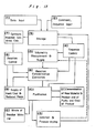
- Sequence Input block (2) If the numbers of the reservoirs containing the raw material, reagents and solvents are not inputted at the Command, Sequence Input block (2), the associated supply sequence is skipped to allow the next succeeding operation to take place. The combination and order of the reaction material is uploaded from the input section into a sequence control table. If no concentration input is carried out, the associated procedure in the sequence table is skipped. Where the solvent extraction and the pH adjustment are required, a step of transferring liquid is carried out. The selection of HPLC, CPC and the dissolving solvent is accomplished by switching the associated valves according to an input command.
- the selective opening and closure of the solenoid valve assemblies associated with the raw material, reagent and solvent supply unit 6 and the reaction unit 7 are controlled and, also, the amount of the raw material to be introduced into the reaction flasks is metered according to the output signal from the gas-liquid boundary sensor.
- the following general reaction formula corresponds to a variety of substituent constants. If the rate constant (k1) of reaction to the product M and the equilibrium constant (k1/k ⁇ 1) are inputted, the reaction constant can be calculated and stored in the storage. From the physical constants stored in the memory, k1 and K for the substituent constants can be calculated.
- the concentration of the reaction reagent (R), and the initial concentration and the volume of the mixture of the raw material which have been specified by a command, input section can be called back so that, in combination with k1 and K, the retention time during which the reagent (R) is added during the reaction as well as the amount thereof can be calculated.
- the rate at which the reagent is added as determined at the block (7) is converted into a pulse signal which is in turn used to control the solenoid valve assembly.
- the concentration and the extraction are executed in response to a command generated as a result of interrogation between the concentration sensor (the thermocouple 43) and the liquid-liquid boundary sensor, respectively. In the event of the absence of the command, the control skips to the next succeeding block.
- the heating or cooling of the flask is carried out by circulating the heating medium or the cooling medium through the jacket of each of the first and second reaction flasks.
- the associated solenoid valve assembly is controlled and the pressure reducing pump is driven.
- the purification unit comprises HPLC device, CPC device and a system of concentration and acidic or basic solution adjustment, and HPLC and CPC can be used either selectively or in series connected fashion.
- the component peak of the eluent eluted from HPLC or CPC is detected and the same peak as the retention time of the raw material is introduced to the waste collecting section.
- the peak of the purified product is used to calculate the purity and yield of the product by determining the relationship between the intensity of the peak, if there is a peak appearing in the neighborhood, and the retention time.
- the resultant fraction is introduced into an isolation and freeze-drying section.
- the purity is lower than the desired value, a signal is generated to the purification section for refinement.
- the resultant fraction is introduced into the isolation section and, at the same time, a signal is generated to the storage for re-starting the synthesizing process.
- the raw material fraction, as determined at the block (11), and the wash-solvent for washing the flow lines are all introduced to the waste collecting section.
- the resultant fraction is introduced into the evaporation vessels and dried.
- the combination of the first and second flasks RF1 and RF2 makes it possible to perform the synthesis process including a maximum number of six steps.
- the solution reaction shown by the above general formulas, the raw material A and B or an intermediate X formed by adding D to a plurality of compounds A, B and C to react therewith is further processed to give F and G (the second step).
- the resultant Y is added with H and J to react therewith thereby to form P (the third step).
- D, F, G and J may be any one of the reagent, catalyst and solvent.
- the product obtained in each of the steps is concentrated under atmospheric or reduced pressure and can be reacted when a reagent is added to the intermediate remaining in the flask.
- the finally purified reaction product can be refined by a combination of the solvent extraction, HPLC and CPC and, as shown in Fig. 14 showing an HPLC chart of the reaction mixture after the refinement, the final powder can be obtained by detecting the peak of the reaction product except for the raw material system, separating the fraction and transferring to a freeze-drying unit.
- a solution of L-phenylalanine tert-butylester acetate in methanol, which was stored in the reservoir RA1 of the supply unit 6 was quantified to a predetermined volume (5 ml, 1.125 g, 4 mmol) by the use of the volumetric tube MT1 and the sensor PS1 and was then introduced into the first reaction flask RF1 of the reaction unit 7 through the solenoid valve assembly SOL1-2.
- a solution of glyoxylic acid in 50% methanol which was stored in the reservoir RK1, was quantified to a predetermined volume (10 ml, 0.368 g, 4mmol) and was then introduced into the first reaction flask RK1.
- the reaction mixture was stirred at room temperature, to which a solution of sodium cyanoborohydride in methanol which was in the reservoir RR1 of the reaction units and was then quantified to a predetermined volume (20 ml, 0.168 g, 2.68 mmol) was subsequently added dropwise in an hour while controlled by the needle valve NV1 and the computer. After the reaction mixture had been stirred for 10 minutes subsequent to the dropwise addition, the reaction liquid is led by the diaphragm pump into the second reaction flask RF2.
- a solution of L-isoleucine tert-butylester acetate in methanol, a solution of sodium 2-ketocaproate in methanol, a solution of sodium cyanoborohydride in methanol and an aqueous solution of 0.8M-sodium hydroxide were contained in the respective reservoirs. While controlled by the computer, the raw materials were quantified to a predetermined amount with the volumetric tube and then introduced into the first reaction flask RF1. Sodium cyanoborohydride solution, which had been quantified to a predetermined volume (20 ml, 2.67 mmol) with the volumetric tube, was added dropwise to the reaction mixture under the control of the computer at room temperature. The reaction mixture was stirred for 20 minutes at room temperature.
- the second preferred embodiment differs from the first preferred embodiment in the following respects.
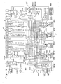
- Fig. 14 illustrates the entire system of the synthesizing apparatus (however, the hot-cold circulatory unit, the wash-solvent supply unit and the exhaust/drainage unit are not shown);
- Fig. 15 illustrates a supply unit 6′;
- Fig. 16 illustrates the plurality of reaction flasks RF10 to RF12 of a reaction unit 7′;
- Fig. 17 illustrates the pH adjusting flask RF13 of the reaction unit 7′;
- Fig. 18 illustrates an extraction/drying device 100 newly added to the reaction unit 7′ in accordance with the second embodiment of the present invention;
- Fig. 19 illustrates a monitoring HPLC device 101 newly added to the reaction unit 7′ in accordance with the second embodiment;
- Fig. 20 illustrates a purifying unit 102, comprised only of a purifying HPLC 102, and a fraction collector unit 103 connected with the purifying unit 102.
- the symbols O represent a solenoid valve and the symbols X represent a gas-liquid or liiquid-liquid sensor.
- Characters V and 0 used at free ends of the various lines represent the introduction of a negative pressure and that of a positive pressure, respectively.
- the supply unit 6′ is, as is the case with the supply unit 6 in the first embodiment, provided with a plurality of reservoirs RR11 to RR26 to which raw materials, reagents and solvents can be automatically supplied from raw materials, reagents or solvents source vessels (not shown)
- Each of the reservoirs is connected with the associated raw materials, reagents or solvents source bath through a supply line L1-20, and a branch line L1-22 connected through a solenoid valve SOL1-20 to a common suction line L1-21 is connected with the respective reservoir.
- the line L1-21 is connected with a diaphragm pump 111 and, by driving the pump 111 and also by activating the solenoid valve SOL1-20 corresponding to one of the reservoirs RR11 to RR26 to which the raw material is desired to be supplied thereby to introduce a negative pressure into such one reservoir, the raw materials, reagents or solvents can be automatically supplied from the associated raw materials, reagents or solvents source vessels to the respective reservoirs.
- a liquid take-out line L1-23 is connected to a lower end of each reservoir and those take-out lines L1-23 are bundled into two to three groups which are in turn connected through respective solenoid valves SOL1-21 with volumetric measuring lines L1-24 having volumetric tubes MT20 and gas-liquid boundary sensors PS20 disposed thereon, so that raw materials, reagents or solvents supplied from the associated reservoirs into the lines L1-23 can be supplied to the volumetric measuring lines L1-24 through the solenoid valves SOL1-21 and can be, after the volumetric measurement, supplied to arbitrary flasks of the reaction unit 7′ by the effect of suction developed in the lines.
- volumetric tube MT and one gas-liquid boundary sensor PS have been described as installed on each of the volumetric measuring lines L1-H24Y, two sets of a pair of volumetric measuring tubes MT20-1 and MT20-2 and two gas-liquid sensors PS20-1 and PS20-2 are employed for the measurement and detection of the different quantities.
- volumetric measuring tubes MT20-1 and MT20-2 By the employment of those plural sets of the volumetric measuring tubes and the sensors, various volumetric measurements can be accomplished for the quick supply of the raw materials, reagents and solvents.
- the reservoirs installed in the supply unit 6, are connected with lines L1-27 so that raw materials, reagents and solvents can be supplied to any one of the flasks to be installed in the reaction unit 7′ as will be described later.
- each of the lines L1-27 shown in Fig. 15 is connected with lines L2-20, which are in turn connected with reaction flasks and pH adjusting flask of the reaction unit 7′ shown in Figs. 16 and 17, in correspondence with a, b, - m, n.
- Solenoid valves SOL1-24 and SOL2-20 are disposed on the lines L1-27 and L2-20 so that, by activating these solenoid valves, arbitrarily chosen reservoirs can be communicated with arbitrarily chosen flasks and, by the introduction of a negative pressure from the diaphragm pump 111 connected with the flasks through lines, required raw materials, reagents, solvents, etc., can be supplied to the respective flask in arbitrarily selected quantity.
- this can be accomplished by changing the solenoid valves and/or by the addition of extra lines.
- the reservoirs RR11 to RR15 are used for the storage of solvents
- the reservoirs RR16 to RR24 are used for the storage of reagents or raw materials
- the reservoirs RR25 and RR26 are used for the storage of pH adjusting liquids. Accordingly, the reservoirs RR25 and RR26 can supply the pH adjusting liquids only to the pH adjusting flasks, as will be described later, of the reaction unit 7′ shown in Fig. 17.
- a compressor 110 for effecting the supply by purging as shown in Figs. 14 and 15. It is, however, to be noted that the illustrated compressor 110 is used for supplying air, etc., to the lines during a washing step.
- the reaction unit 7′ differs from the first embodiment in that three reaction flasks RF10, RF11 and RF12 are employed in the reaction unit 7′, to which flasks the raw materials, reagents and solvents can be supplied directly from the arbitrary reservoirs RR11 to RR24 of the supply unit 6, through the lines L1-27 and L2-20 and in that circulation can be effected among these three reaction flasks RF10, RF11 and RF12 to effect a transfer of a reaction liquid as will be described later.
- the first reaction flask RF10 and the second reaction flask RF11 are similar in construction to each other and also similar in construction to the reaction flask RF provided in the reaction unit 7 in the first embodiment and is provided with circulating jackets 25D and 25E for the circulation of a heating medium or a cooling medium and stirrers 26D and 26E, both of the said jackets and stirrers being installed therearound.
- the reaction flask RF10 and RF11 in the second embodiment is provided with coolant tubes (condensers) 112A and 112B communicated with the respective interiors thereof.
- the third reaction flask RF12 is used when heating to a higher temperature than any one of the first and second reaction flasks is desired to be effected or when the temperature is desired to be arbitrarily adjusted, and is surrounded with an oil bath 113 having a heater 114 installed therein for controlling the temperature as desired up to 200°C.
- the reaction flask RF12 is also provided with a coolant tube 112C and a stirrer 26F.
- reaction flasks RF10 and RF11 are used, but where the reaction is desired to be effected at a relatively high temperature or where the temperature is desired to be arbitrarily changed, the reaction flask RF12 is used.
- the reaction flasks RF10, RF11 and RF12 are connected with the compressor 110 through the lines L2-21 and also with the diaphragm pump 111 through the lines L222 so that at appropriate timings air or an inert gas such as nitrogen, argon, helium, etc. can be supplied to effect a bubbling inside these reaction flasks.
- the lines L2-21 and L2-22 are provided with solenoid valves SOL2-21 and SOL2-22 in correspondence with the reaction flasks so that stirring by bubbling can take place only in the required flasks. It is to be noted that the stirring by bubbling is employed where the mixture within the reaction flasks cannot be satisfactorily stirred with the stirrers 26D to 26F.
- the pH adjusting flask RF13 paralleled with the reaction flasks RF10 to RF12 in the reaction unit 7′ is also connected with a heating or cooling medium circulating jacket 25F, a stirrer 26G and a line L2-22.
- the pH adjusting flasks RF13 and the reaction flasks RF10, RF11 and RF12 are mutually connected with each other by supply lines L2-33 extending from the reaction flasks to the pH adjusting flasks and output lines L2-24 extending from the pH adjusting flasks to the reaction flasks so that after the pH adjustment the reaction liquid can be transferred to any desired reaction flasks.
- the lines L2-23 and L2-24 are provided with solenoid valves SOL2-23 and SOL2-24 corresponding to the respective reaction flasks so that, by switching these solenoid valves SOL2-23 and SOL2-24, the mixed liquid within the required reaction flasks can be introduced into the pH adjusting flasks. It is also possible to transfer the mixed liquid among the reaction flasks RF10, RF11 and RF12 without being passed through the pH adjusting flask RF13.
- mixed liquid take-out lines L2-25 and the supply lines L2-23 are connected together through solenoid valves SOL2-25, and, at the same time, re-supply lines L2-26 is connected with the output lines L2-24 through solenoid valves SOL2-26 so that the removal of the mixed liquid from each of the reaction flasks and the re-supply into each of the reaction flasks can be carried out.
- Fig. 18 illustrates an extraction/drying device 100 added to the reaction unit 7′ and comprises an extracting/separating funnel 115 and a plurality of parallel drying tubes 116.
- the extracting/separating funnel 115 is selectively connected with the reaction flasks RF10, RF11 and RF12 through supply lines L2-30 and solenoid valves SOL2-30 and SOL2-40 corresponding to the respective reaction flasks so that the mixed liquid within the predetermined reaction flasks RF10, RF11 and RF12 can be introduced into the extracting/separating funnel 115.
- An exit at the lower end of the extracting/separating funnel 115 is connected with the drying tubes 116 through lines L2-31 having respective sensors LS21 disposed thereon so that an organic layer separated in the funnel 115 can be supplied to the drying tubes 116.
- a line L2-36 connected with the diaphragm pump 111 is connected with the funnel 115 and, by opening a solenoid valve SOL2-31 disposed on the line L2-31, the funnel 115 can be reduced in pressure.
- a storage bottle SF20 is connected to the line L2-31 through a line L2-33 for storing the water layer beforehand.
- each of the drying tubes 116 has a drying agent such as anhydrous sodium sulfate filled therein for dehydrating the organic layer then flowing therethrough and is provided with a glass filter 117 for the removal of insoluble matters.
- Solenoid valves SOL2-33 and SOL2-34 are disposed on lines L2-34 connecting between the drying tubes 116 and the reaction flasks RF10, RF11 and RF12 so that the reaction liquid having been dried can be returned to the arbitrary reaction flasks.
- the extracting procedure can be repeated in a desired or required number of times.
- Fig. 19 illustrates a monitoring HPLC device 101 added to the reaction unit 7′, which device 101 is operable to supply a small quantity of the mixed reaction liquid arbitrarily from the reaction flask RF10, RF11 and RF12 to analyze and monitor the conditions and progress of the reaction.
- main lines L6-1 of the device 101 are connected through respective solenoid valves SOL61 with lines L6-2 connected to the reaction flasks RF10, RF11 and RF12.
- the lines L6-2 is connected through solenoid valves SOL241 to the lines L2-25 for the removal of the liquids from the reaction flasks and, accordingly, the mixed reaction liquid can be supplied from the arbitrary reaction flasks to the monitoring HPLC device for the analysis of the reaction conditions.
- This monitoring HPLC is generally similar in structure and operation to preparative HPLC of the purification unit 8 used in and described in connection with the first embodiment of the present invention.
- the mixed reaction liquid supplied from the reaction flask is stored and diluted to an arbitrary concentration, and is provided with a storage bottle SF21 for the storage of the diluted liquid, a column SC20, HPLC pump HP20, dissolving solution supply sections SR20 and 21, a transfer pump TP20 for introducing a predetermined quantity of sample from the storage bottle SF21 to a sample loop, a six-way rotary valve RV20, a UV absorption detector DE20, and sensors PS22 and PS23.
- Fig. 20 illustrates a preparative HPLC 102 for purification.
- purification is carried out only with the use of HPLC 102 and the resultant purified product is supplied to the fraction collector 103 connected therewith.
- the supply lines L2-42 from the reaction flasks RF10, RF11 and RF12 are connected through solenoid valves SOL7-1 to main lines L7-1 of the purifying HPLC 102 so that, by switching the solenoid valves the reaction liquids can be supplied directly to the purifying HPLC 102 either from the reaction flasks RF10, RF11 and RF12 through the re-supply lines leading to the reaction flasks.
- the purifying HPLC 102 is generally similar in structure to the monitoring HPLC 101 and comprises a reservoir SF22 for the storage of the liquid from the reaction flasks, columns SC21 and SC22, dissolving liquid supply baths SR22 and SR23, a HPLC pump HP21, a transfer pump TP21 for introducing a predetermined quantity of the reaction liquid into a sample loop, a six-way rotary valves RV21, four-way rotary valves RV22 and RV23, a sensor PS25, and a UV absorption detector ED21.
- Efluent from the columns SC21 or SC22 is, after having measured as to the UV absorption by the detector ED21, supplied through supply lines L8-1 to the fraction collector 103 and then to a plurality of vessels 120 disposed in the fraction collector 103 for the collection of the final product.
- the supply of the reaction product is possible from any one of the reaction flasks RF10, RF11 and RF12 and the pH adjusting flasks to the purifying HPLC 102 and the supply of the resultant liquid collected in the fraction collector 103 after the purification in HPLC is also possible from the fraction collector 103 to any one of the reaction flasks RF10, RF11 and RF12.
- reaction flasks RF10, RF11 and RF12 The relationships in connection among the reaction flasks RF10, RF11 and RF12, the pH adjusting flasks 13, the extracting/drying device 100, the monitoring HPLC 101, the purifying HPLC 102 and the fraction collector 103 are shown by A, B to T and U in the drawings.
- line filters 130 are disposed in the vicinity of exits of the reaction flasks, portions at which the liquid or the air is introduced or discharged, and also in the vicinity of the various valves.
- the second embodiment of the present invention is featured in that the lines are installed through the solenoid valves for the selective opening and closure of the associated lines so that the raw materials, reagents and solvents can be supplied from the supply unit 6′ to any one of the reaction flasks of the reaction unit and in that circulation is possible from the reaction flasks RF10, RF11 and RF11 to the pH adjusting flasks RF13, the extracting/drying device 100, the monitoring HPLC 101, the purifying HPLC 102 and the fraction collector 103 and vice versa. Accordingly, the required operating procedures can be repeated in a desired number of times and, also unnecessary steps can be dispensed of while allowing the reaction of interest to be readily proceeded.
- reaction unit is provided with the oil bath 113 having the coolant tubes (condensers) 112A to 112C and the heater 114 for heating to a relatively high temperature, in place of the technique of circulating the heating medium or the cooling medium, and since the bubbling induced by the blow of the air or the like is employed for accomplishing the stirring, the rate of reaction taking place within the reaction flasks can be accelerated.
- This experiment is directed to the synthesis of a final product F with the use of raw materials (reagents) A and B according to the flow chart shown in Fig. 22. It is, however, needless to say that by combining the steps in a desired manner, it can be rendered to be many steps.
- An ether solution, which is the raw material A (15 mmol) and is contained in the reservoir RR16 of the supply unit 6′ was quantified to 15 ml by the use of the volumetric tubes MT20-1 and MT20-2 and the sensors PS20-1, PS20-2 and was then introduced into the reaction flask RF10. Thereafter, the solution was stirred at 0°C for 3 minutes.
- an ether solution which is the raw material B and is contained in the reservoir RR18 was quantified to 15 ml (30 mmol) with the use of the volumetric tubes and the sensor PS20 and was introduced dropwise into the reaction flask RF10 (at a rate of 10 sec x 100 times).
- the resultomg reaction mixture was stirred at 0°C for 30 minutes, to which water (30 ml) which had been quantified to the volume (10 ml x 3 times) with the use of the volumetric tube and the sensor was subsequently added. After stirring for 3 minutes, the resulting two-phase mixture was transferred to the extracting/separating funnel 115 of the extracting/drying device 100 with the use of the diaphragm pump 111. After the mixture had been allowed to stand for 3 minutes for the separation of the two-phase mixture into upper and lower layers, the separated upper organic layer was introduced into the reaction flask RF12 through any one of the drying tubes 116 filled with drying agent (anhydrous Na2SO4, 65g).
- drying agent anhydrous Na2SO4, 65g
- Ethyl acetate stored in the reservoir RR13 was introduced into the reaction flask RF10 after having been quantified by the volumetric tube MT20 and the sensor PS20 to 30 ml (10 ml x 3 times).
- the ethyl acetate solution (30 ml) within the reaction flask RF10 was transferred to the extracting/separating funnel 115 of the extraction/drying device 100, and air was bubbled up through the funnel 115 to help re-extraction and then the separated organic layer was passed through the drying tube 116 before being collected in the reaction flask RF12.
- the organic solution collected in the reaction flask RF12 was concentrated under reduced pressure at 50°C for 15 minutes, and methanol from the reservoir RR14 was introduced, after having been quantified by the volumetric tube MT20-2 and the sensor PS20-1, to 10 ml, to dissolve the concentrated residue.
- An ethanol solution (20 ml, 15 mmol which is the reagent C and is stored in the reservoir RR23 was introduced into the reaction flask RF12 after having been quantified by the volumetric tubes and the sensors.
- the resultant reaction mixture was heated with stirring at 70°C for one hour and then a reagent D (10 ml x 2 times, 15 mmol) stored in the reservoir RR15 was added thereto after having been quantified by the volumetric tubes MT10-1, MT20-2 and the sensors PS20, PS20-2. Then, a reagent E (5 ml x 4 times, 15 mmol) stored in the reservoir RR24 was, after having been quantified by the volumetric tubes and the sensors, added to the reaction flask RF12. The reaction mixture was refluxed at 100°C for 90 minutes and then concentrated under reduced pressure at 50°C.
- the dehydrated organic layer was then collected in the reaction flask RF11 and concentrated under reduced pressure at 50°C.
- a solvent (chloroform) stored in the reservoir RR21 was, after having been quantified by the volumetric tubes and the sensors to a predetermined volume (15 ml), introduced into the reaction flask RF11. The mixture was then bubbled with air and stirred to dissolve the residue.
- the resulting chloroform solution was transferred to the reservoir SF22 of the purification HPLC device 102 and then charged onto the column SC21 of Lichroprop SI-60 (Merck, 25-40 um, 20 x 500 mm) and eluted first by chloroform and then by a mixture of chloroform : methanol 45:1) to give the target product F.
- the concentrated product obtained in Experimental 3 described above is transferred to the reaction flask RF11.
- Hot medium liquid heated to 70°C is circulated through a flask of the reaction flask RF11 to effect the concentration under reduced pressure (15 minutes).
- MeOH stored in the reservoir RR14 was, after having been quantified by the volumetric tube and the sensor to 10 ml, transferred to the reaction flask RF11 to dissolve the residue.
- a reagent stored in the reservoir RR21 was then, after having been quantified by the sensor of the volumetric tube to 5 ml, transferred to the reaction flask RF11. This procedure was repeated four times so that 20 ml in total could be added.
- Hot medium liquid of 70°C was circulated to heat the reaction mixture for one hour.
- a reagent stored in the reservoir RR26 and quantified by the sensor of the volumetric tube to 10 ml was transferred to the reaction flask RF11. This procedure is repeated two times so that 20 ml in total could be added.
- a reagent stored in the reservoir RR22 and quantified by the sensor of the volumetric tube to 5 ml was then transferred to the reaction flask RF11. This procedure was repeated four times so that 20 ml in total could be added.
- Hot medium liquid of 70°C was circulated to heat the reaction mixture for 90 minutes. After the concentration had been effected under reduced pressure while the hot medium liquid was circulated, 30 ml of water was added in a similar manner from the reservoir RR11.
- Ethyl acetate stored in the reservoir RR13 and subsequently quantified by the sensor PS20 of the volumetric tube MT20 to 10 ml was then transferred to the flask RF11. This was repeated three times so that 30 ml in total could be added. After the bubbling was effected to stir and the extraction was then made, the mixture was transferred to the washed extracting/separating funnel 115. In a manner similar to that described hereinabove, the organic layer was separated and was, after having been passed through the drying tube 116 for drying, transferred to the reaction flask RF12. The water layer was repeatedly extracted and dried with 30 ml of ethyl acetate.
- a reagent stored in the reservoir RR16 and subsequently quantified by the PS sensor of the volumetric tube to 15 ml was transferred to the reaction flask RF12.
- a reagent stored in the reaction reservoir 18 and subsequently quantified by the sensor of the volumetric tube was transferred to the reaction flask RF12. While this was stirred, a heated circulation was carried out for 60 minutes at 110°C. Water stored in the reservoir RR11 and subsequently quantified by the sensor of the volumetric tube to 10 ml was transferred to the reaction flask RF12. This was repeated three times and 30 ml of water was added to effect the stirring and extraction for 3 minutes.
- the resulting upper organic layer is discriminated and separated by the LS sensor.
- the separated upper layer was then passed through the drying tube 116 having drying agent (anhydrous Na2SO4, 6.5 g) filled therein and was then transferred to the reaction flask RF10 in units of limited amounts.
- drying agent anhydrous Na2SO4, 6.5 g
- the separated organic layer was dried in the same manner as that during the previous cycle and was then transferred to the reaction flask RF10.
- the extract within the reaction flask RF10 was transferred to the reaction flask RF12.
- the temperature of the oil bath was set at 50°C and the concentration was carried out under reduced pressure (for 15 minutes).
- MeOH stored in the reservoir RR14 and subsequently quantified by the sensor of the volumetric tube was transferred to the reaction flask RF12 to dissolve the residue.
- a reagent stored in the reservoir RR19 and subsequently quantified by the sensor of the volumetric tube to 5 ml was transferred to the reaction flask RF12. This was repeated four times to result in the addition of 20 ml in total.
- the automated synthesis apparatus is effective to automatically yield a variety of products from a variety of combination of substituents.
- the apparatus of the present invention is effective to accomplish a mass production of a variety of derivatives from a small quantity of raw material at different reaction conditions and, therefore, the development of novel pharmaceutical products can be effectively expected automatically.
- the apparatus of the present invention since the apparatus of the present invention is fully automated, it can be run for 24 hours a day, and the average rate of synthesis of N-(carboxyalkyl)amino acids can be three compounds daily.
- the fact that the synthesis can be accomplished automatically and with no need of manual intervention can greatly contribute to the synthesis of many derivatives of one particular chemical compound. Even if the chemical yields are low under optimum conditions, it is still possible to obtain a sufficient amount of the desired product by repetition of the reaction.
Landscapes
- Chemical & Material Sciences (AREA)
- Organic Chemistry (AREA)
- Chemical Kinetics & Catalysis (AREA)
- Engineering & Computer Science (AREA)
- Manufacturing & Machinery (AREA)
- Physical Or Chemical Processes And Apparatus (AREA)
- Organic Low-Molecular-Weight Compounds And Preparation Thereof (AREA)
Applications Claiming Priority (2)
| Application Number | Priority Date | Filing Date | Title |
|---|---|---|---|
| JP59004/88 | 1988-03-11 | ||
| JP5900488 | 1988-03-11 |
Publications (2)
| Publication Number | Publication Date |
|---|---|
| EP0332452A1 true EP0332452A1 (de) | 1989-09-13 |
| EP0332452B1 EP0332452B1 (de) | 1994-06-15 |
Family
ID=13100707
Family Applications (1)
| Application Number | Title | Priority Date | Filing Date |
|---|---|---|---|
| EP89302370A Expired - Lifetime EP0332452B1 (de) | 1988-03-11 | 1989-03-10 | Automatische Synthesevorrichtung |
Country Status (5)
| Country | Link |
|---|---|
| US (2) | US5164159A (de) |
| EP (1) | EP0332452B1 (de) |
| JP (1) | JP2755350B2 (de) |
| DE (1) | DE68916069T2 (de) |
| IE (1) | IE64511B1 (de) |
Cited By (4)
| Publication number | Priority date | Publication date | Assignee | Title |
|---|---|---|---|---|
| EP0510487A1 (de) * | 1991-04-17 | 1992-10-28 | Takeda Chemical Industries, Ltd. | Automatische Synthesevorrichtung und Verfahren zur Steuerung der Vorrichtung |
| US5499193A (en) * | 1991-04-17 | 1996-03-12 | Takeda Chemical Industries, Ltd. | Automated synthesis apparatus and method of controlling the apparatus |
| WO1997024181A1 (en) * | 1995-12-29 | 1997-07-10 | Takeda Chemical Industries, Ltd. | Apparatus and method for synthesizing a variety of chemical compounds in a single batch |
| WO2021022469A1 (zh) * | 2019-08-06 | 2021-02-11 | 吉林凯莱英医药化学有限公司 | 连续化合成-纯化一体装置及含有其的连续化反应系统 |
Families Citing this family (56)
| Publication number | Priority date | Publication date | Assignee | Title |
|---|---|---|---|---|
| US5595707A (en) | 1990-03-02 | 1997-01-21 | Ventana Medical Systems, Inc. | Automated biological reaction apparatus |
| EP0653965B1 (de) * | 1992-07-06 | 1996-05-15 | Beckman Instruments, Inc. | Flüssigkeitsversorgungssystem mit Mehrwegventil |
| US5923571A (en) * | 1994-10-11 | 1999-07-13 | Betzdearborn, Inc. | Apparatus and method for automatic congruent control of multiple boilers sharing a common feedwater line and chemical feed point |
| US5696696A (en) * | 1994-10-11 | 1997-12-09 | Betzdearborn, Inc. | Apparatus and method for automatically achieving and maintaining congruent control in an industrial boiler |
| US6359114B1 (en) * | 1995-06-07 | 2002-03-19 | Aphton Corp. | System for method for the modification and purification of proteins |
| CA2230592A1 (en) * | 1995-09-29 | 1997-04-03 | Ian Henderson | A solid phase synthesis reaction vessel and method of using the same |
| US5849598A (en) * | 1996-03-15 | 1998-12-15 | Washington University | Method for transferring micro quantities of liquid samples to discrete locations |
| KR100454611B1 (ko) | 1996-10-30 | 2005-06-10 | 스미또모 가가꾸 고오교오 가부시끼가이샤 | 합성실험자동화시스템및분액처리장치와반응용기 |
| US6890491B1 (en) * | 1997-06-10 | 2005-05-10 | Pharmacopeia Drug Discovery, Inc. | Method and apparatus for universal fluid exchange |
| EP1614473A3 (de) * | 1998-05-01 | 2007-03-14 | Gen-Probe Incorporated | Mehrfachringaufbau zum liefern von Proben an Reaktionsbehälter in einer automatischen Analysevorrichtung |
| US6548026B1 (en) | 1998-08-13 | 2003-04-15 | Symyx Technologies, Inc. | Parallel reactor with internal sensing and method of using same |
| US6528026B2 (en) | 1998-08-13 | 2003-03-04 | Symyx Technologies, Inc. | Multi-temperature modular reactor and method of using same |
| US6455316B1 (en) | 1998-08-13 | 2002-09-24 | Symyx Technologies, Inc. | Parallel reactor with internal sensing and method of using same |
| US6890492B1 (en) | 1998-08-13 | 2005-05-10 | Symyx Technologies, Inc. | Parallel reactor with internal sensing and method of using same |
| US6306658B1 (en) | 1998-08-13 | 2001-10-23 | Symyx Technologies | Parallel reactor with internal sensing |
| EP1174183B1 (de) * | 1998-08-13 | 2004-10-20 | Symyx Technologies, Inc. | Vorrichtung zur parallelen Behandlung von Reaktionsgemischen |
| JP4067685B2 (ja) * | 1999-03-26 | 2008-03-26 | 山善株式会社 | インジェクション装置 |
| GB9909630D0 (en) * | 1999-04-28 | 1999-06-23 | Zeneca Ltd | Reactor |
| US7033840B1 (en) | 1999-11-09 | 2006-04-25 | Sri International | Reaction calorimeter and differential scanning calorimeter for the high-throughput synthesis, screening and characterization of combinatorial libraries |
| WO2001034290A2 (en) | 1999-11-09 | 2001-05-17 | Sri International | Array for generating combinatorial libraries |
| US6994827B2 (en) * | 2000-06-03 | 2006-02-07 | Symyx Technologies, Inc. | Parallel semicontinuous or continuous reactors |
| US6692708B2 (en) * | 2001-04-05 | 2004-02-17 | Symyx Technologies, Inc. | Parallel reactor for sampling and conducting in situ flow-through reactions and a method of using same |
| US6582116B2 (en) | 2001-09-24 | 2003-06-24 | Symyx Technologies, Inc. | Apparatus and method for mixing small volumes of reaction materials |
| US20030190260A1 (en) * | 2002-04-05 | 2003-10-09 | Symyx Technologies, Inc. | Combinatorial chemistry reactor system |
| US20030219363A1 (en) * | 2002-05-17 | 2003-11-27 | Kobylecki Ryszard J. | Examining chemical reactions |
| US7648678B2 (en) | 2002-12-20 | 2010-01-19 | Dako Denmark A/S | Method and system for pretreatment of tissue slides |
| US20040136873A1 (en) * | 2003-01-09 | 2004-07-15 | Argonaut Technologies, Inc. | Modular reactor system |
| JP4571938B2 (ja) * | 2003-06-06 | 2010-10-27 | ウオーターズ・テクノロジーズ・コーポレイシヨン | 並列プロセスを実行する装置および方法 |
| US20050232074A1 (en) * | 2004-04-20 | 2005-10-20 | Symyx Technologies, Inc. | Pressurized reactor apparatus with magnetic stirring |
| WO2007022110A2 (en) * | 2005-08-12 | 2007-02-22 | Symyx Technologies, Inc. | Event-based library process design |
| EP2364777B1 (de) * | 2007-02-13 | 2018-07-25 | Eppendorf AG | Verfahren zur steuerung der temperatur von proben |
| JP2009166039A (ja) * | 2009-03-11 | 2009-07-30 | Tosoh Corp | 微粒子製造装置 |
| CN101920127B (zh) * | 2009-06-15 | 2013-03-06 | 福建中烟工业有限责任公司 | 一种天然植物香味成分的低温提取装置及流程 |
| CN101921658A (zh) * | 2009-06-15 | 2010-12-22 | 福建中烟工业公司 | 一种用溴甲烷提取天然植物挥发性香味成分的方法 |
| US8734736B2 (en) | 2009-10-06 | 2014-05-27 | Lester F. Ludwig | Valve-manifold laboratory glassware for chemical laboratory automation and other application |
| EP2578286A1 (de) | 2011-10-04 | 2013-04-10 | Merck Patent GmbH | Verfahren und Vorrichtung zur chromatographischen Aufreinigung |
| DE112012006845T5 (de) * | 2012-08-24 | 2015-06-03 | Centennial Technology Company | Probenvorbehandlungsvorrichtung und Probenvorbehandlungsverfahren |
| US10195610B2 (en) | 2014-03-10 | 2019-02-05 | Click Diagnostics, Inc. | Cartridge-based thermocycler |
| US10780410B2 (en) | 2014-08-15 | 2020-09-22 | Massachusetts Institute Of Technology | Systems and methods for synthesizing chemical products, including active pharmaceutical ingredients |
| JP6778194B2 (ja) | 2014-12-31 | 2020-10-28 | ビスビュー メディカル,インコーポレイテッド | 分子診断試験のためのデバイス及び方法 |
| EP3331890B1 (de) | 2015-08-07 | 2021-11-24 | The Board of Trustees of the University of Illinois | Geschützte organoborsäuren mit abstimmbarer reaktivität und verfahren zur verwendung davon |
| EP3192583A1 (de) * | 2016-01-12 | 2017-07-19 | ETH Zurich | Vorrichtung und verfahren zur automatisierten chemischen synthese von verbindungen |
| EP3210667A1 (de) * | 2016-02-29 | 2017-08-30 | Max-Planck-Gesellschaft zur Förderung der Wissenschaften e.V. | Modulare vorrichtung für kontinuierlichen fluss |
| US10987674B2 (en) | 2016-04-22 | 2021-04-27 | Visby Medical, Inc. | Printed circuit board heater for an amplification module |
| US11185839B2 (en) | 2016-05-02 | 2021-11-30 | Massachusetts Institute Of Technology | Reconfigurable multi-step chemical synthesis system and related components and methods |
| WO2017197040A1 (en) | 2016-05-11 | 2017-11-16 | Click Diagnostics, Inc. | Devices and methods for nucleic acid extraction |
| USD800331S1 (en) | 2016-06-29 | 2017-10-17 | Click Diagnostics, Inc. | Molecular diagnostic device |
| WO2018005710A1 (en) | 2016-06-29 | 2018-01-04 | Click Diagnostics, Inc. | Devices and methods for the detection of molecules using a flow cell |
| USD800914S1 (en) | 2016-06-30 | 2017-10-24 | Click Diagnostics, Inc. | Status indicator for molecular diagnostic device |
| USD800913S1 (en) | 2016-06-30 | 2017-10-24 | Click Diagnostics, Inc. | Detection window for molecular diagnostic device |
| KR20200079264A (ko) | 2017-11-09 | 2020-07-02 | 비스비 메디컬, 인코포레이티드 | 표적 바이러스 검출을 위한 휴대용 분자 진단 디바이스 및 방법 |
| CN109453544A (zh) * | 2019-01-04 | 2019-03-12 | 朗慕 | 高效自动液液萃取机 |
| EP4010111A4 (de) * | 2019-08-05 | 2023-08-16 | Academia Sinica | Mikroreaktor und verfahren zur verwendung |
| USD1055307S1 (en) | 2021-08-13 | 2024-12-24 | Visby Medical, Inc. | Molecular diagnostic device |
| CN116272725A (zh) * | 2023-02-28 | 2023-06-23 | 浙江大学 | 一种生化反应系统及控制方法 |
| GB2642679A (en) * | 2024-07-15 | 2026-01-21 | Chemastery Group Ltd | A chemical processing system |
Citations (2)
| Publication number | Priority date | Publication date | Assignee | Title |
|---|---|---|---|---|
| EP0156588A2 (de) * | 1984-03-23 | 1985-10-02 | Applied Biosystems, Inc. | Automatisierter Polypeptidsyntheseapparat |
| GB2161815A (en) * | 1984-07-20 | 1986-01-22 | Nippon Zeon Co | Polynucleotide synthesizing apparatus |
Family Cites Families (22)
| Publication number | Priority date | Publication date | Assignee | Title |
|---|---|---|---|---|
| US3321280A (en) * | 1964-06-26 | 1967-05-23 | Exxon Research Engineering Co | Computer control method for production of butyl rubber |
| US3459304A (en) * | 1966-12-08 | 1969-08-05 | George R Brenchley | Photosensitive fluid monitoring device |
| US3794566A (en) * | 1971-10-28 | 1974-02-26 | Canadian Patents Dev | Vapor-liquid equilibrium still |
| US3951741A (en) * | 1973-07-10 | 1976-04-20 | Peter Pfaender | Process and apparatus for the synthesis of peptides by use of n-carboxyanhydrides |
| JPS5384878A (en) * | 1976-12-30 | 1978-07-26 | Daiki Engineering Co | Chemical reaction automatic controll method |
| GB1589660A (en) * | 1978-05-08 | 1981-05-20 | Smidth & Co As F L | Method and apparatus for controlling the burning of caco3 and/or mgco3 containing materials |
| GB2043030A (en) * | 1979-02-27 | 1980-10-01 | Pye Electronic Prod Ltd | Flushing container for sampling probe |
| CA1136378A (en) * | 1979-05-31 | 1982-11-30 | Erco Industries Limited | Small scale chlorine dioxide plant |
| JPS58148896A (ja) * | 1982-02-26 | 1983-09-05 | Shimadzu Corp | Dna等微量自動合成装置 |
| US4488239A (en) * | 1982-04-22 | 1984-12-11 | The Babcock & Wilcox Company | Temperature control system for olefin oxidation reactor |
| US4472355A (en) * | 1982-08-26 | 1984-09-18 | Westinghouse Electric Corp. | Concentrator apparatus |
| JPS59216830A (ja) * | 1983-05-25 | 1984-12-06 | Takeda Chem Ind Ltd | 放射性物質を含む化合物の小型自動合成装置 |
| US4798798A (en) * | 1983-08-17 | 1989-01-17 | Kraft, Inc. | Apparatus for monitoring a chemical process |
| US4598049A (en) * | 1983-08-31 | 1986-07-01 | Systec Inc. | General purpose gene synthesizer |
| JPS6064995A (ja) * | 1983-09-19 | 1985-04-13 | Japan Steel Works Ltd:The | グルコ−ス自動合成装置 |
| JPS6064934A (ja) * | 1983-09-19 | 1985-04-13 | Japan Steel Works Ltd:The | ヨウ化メチル自動合成装置 |
| US4746490A (en) * | 1983-09-22 | 1988-05-24 | Saneii Hossain H | Solid phase peptide synthesizer |
| US4621062A (en) * | 1984-04-27 | 1986-11-04 | Phillips Petroleum Company | Control of an isomerization process |
| US4701304A (en) * | 1985-04-19 | 1987-10-20 | Applied Protein Technologies, Inc. | Apparatus for automated synthesis of peptides |
| US4835707A (en) * | 1986-07-23 | 1989-05-30 | Takeda Chemical Industries, Ltd. | Automatic analysis method and apparatus for enzyme reaction |
| US4802981A (en) * | 1987-11-04 | 1989-02-07 | Oros Systems Limited | Automatic chromatography apparatus |
| US4920056A (en) * | 1988-02-19 | 1990-04-24 | The Dow Chemical Company | Apparatus and method for automated microbatch reaction |
-
1989
- 1989-03-09 IE IE76689A patent/IE64511B1/en not_active IP Right Cessation
- 1989-03-10 EP EP89302370A patent/EP0332452B1/de not_active Expired - Lifetime
- 1989-03-10 DE DE68916069T patent/DE68916069T2/de not_active Expired - Fee Related
- 1989-03-10 JP JP1058196A patent/JP2755350B2/ja not_active Expired - Fee Related
- 1989-03-10 US US07/321,748 patent/US5164159A/en not_active Expired - Fee Related
-
1993
- 1993-05-03 US US08/055,786 patent/US5316728A/en not_active Expired - Fee Related
Patent Citations (2)
| Publication number | Priority date | Publication date | Assignee | Title |
|---|---|---|---|---|
| EP0156588A2 (de) * | 1984-03-23 | 1985-10-02 | Applied Biosystems, Inc. | Automatisierter Polypeptidsyntheseapparat |
| GB2161815A (en) * | 1984-07-20 | 1986-01-22 | Nippon Zeon Co | Polynucleotide synthesizing apparatus |
Cited By (4)
| Publication number | Priority date | Publication date | Assignee | Title |
|---|---|---|---|---|
| EP0510487A1 (de) * | 1991-04-17 | 1992-10-28 | Takeda Chemical Industries, Ltd. | Automatische Synthesevorrichtung und Verfahren zur Steuerung der Vorrichtung |
| US5499193A (en) * | 1991-04-17 | 1996-03-12 | Takeda Chemical Industries, Ltd. | Automated synthesis apparatus and method of controlling the apparatus |
| WO1997024181A1 (en) * | 1995-12-29 | 1997-07-10 | Takeda Chemical Industries, Ltd. | Apparatus and method for synthesizing a variety of chemical compounds in a single batch |
| WO2021022469A1 (zh) * | 2019-08-06 | 2021-02-11 | 吉林凯莱英医药化学有限公司 | 连续化合成-纯化一体装置及含有其的连续化反应系统 |
Also Published As
| Publication number | Publication date |
|---|---|
| JPH022870A (ja) | 1990-01-08 |
| IE64511B1 (en) | 1995-08-09 |
| US5164159A (en) | 1992-11-17 |
| JP2755350B2 (ja) | 1998-05-20 |
| IE890766L (en) | 1989-09-11 |
| DE68916069T2 (de) | 1994-10-13 |
| US5316728A (en) | 1994-05-31 |
| EP0332452B1 (de) | 1994-06-15 |
| DE68916069D1 (de) | 1994-07-21 |
Similar Documents
| Publication | Publication Date | Title |
|---|---|---|
| EP0332452A1 (de) | Automatische Synthesevorrichtung | |
| US5499193A (en) | Automated synthesis apparatus and method of controlling the apparatus | |
| US6197198B1 (en) | Method and device for parallel chromatography | |
| US11731101B2 (en) | Modular continuous flow device | |
| EP0510487B1 (de) | Automatische Synthesevorrichtung und Verfahren zur Steuerung der Vorrichtung | |
| Sugawara et al. | Development of fully‐automated synthesis systems | |
| JP2708456B2 (ja) | 自動合成装置 | |
| WO2024061972A1 (en) | Methods and platform for chemical synthesis | |
| US20080015117A1 (en) | Reactor for automated protein analysis | |
| CN216386898U (zh) | 一种新型液相色谱柱前衍生装置 | |
| KR101689321B1 (ko) | 방사성 화합물 합성 장치용 인터페이스 및 그의 조작방법 | |
| JPH0416446B2 (de) | ||
| JPH0826975A (ja) | ▲11c▼標識カルボキシル化合物の注射用製剤の自動合成装置および自動合成方法 | |
| JP4081539B2 (ja) | 高圧反応システム | |
| JPH09235241A (ja) | 多種化合物同時自動合成装置および自動合成方法 | |
| WO2026033142A1 (en) | Chemical processing platform | |
| JP3223600B2 (ja) | エドマン反応装置 | |
| WO1997024181A1 (en) | Apparatus and method for synthesizing a variety of chemical compounds in a single batch | |
| KR20250136119A (ko) | 분리 정제 모듈 및 이를 포함하는 자동화 물질 반응 시스템 | |
| JPH11156184A (ja) | 試料合成装置 | |
| CN119667181A (zh) | 提取分析系统 | |
| JP4583701B2 (ja) | 液相系自動有機合成装置 | |
| CN119633706A (zh) | 一种造影剂宏量制备系统、方法及控制器 | |
| CA2239037A1 (en) | Apparatus and method for synthesizing a variety of chemical compounds in a single batch | |
| JPH09150053A (ja) | 自動合成装置および該装置の制御方法 |
Legal Events
| Date | Code | Title | Description |
|---|---|---|---|
| PUAI | Public reference made under article 153(3) epc to a published international application that has entered the european phase |
Free format text: ORIGINAL CODE: 0009012 |
|
| AK | Designated contracting states |
Kind code of ref document: A1 Designated state(s): CH DE FR GB IT LI NL |
|
| 17P | Request for examination filed |
Effective date: 19900102 |
|
| 17Q | First examination report despatched |
Effective date: 19910410 |
|
| RAP3 | Party data changed (applicant data changed or rights of an application transferred) |
Owner name: TAKEDA CHEMICAL INDUSTRIES, LTD. |
|
| GRAA | (expected) grant |
Free format text: ORIGINAL CODE: 0009210 |
|
| AK | Designated contracting states |
Kind code of ref document: B1 Designated state(s): CH DE FR GB IT LI NL |
|
| ITF | It: translation for a ep patent filed | ||
| REF | Corresponds to: |
Ref document number: 68916069 Country of ref document: DE Date of ref document: 19940721 |
|
| ET | Fr: translation filed | ||
| PLBE | No opposition filed within time limit |
Free format text: ORIGINAL CODE: 0009261 |
|
| STAA | Information on the status of an ep patent application or granted ep patent |
Free format text: STATUS: NO OPPOSITION FILED WITHIN TIME LIMIT |
|
| 26N | No opposition filed | ||
| PGFP | Annual fee paid to national office [announced via postgrant information from national office to epo] |
Ref country code: DE Payment date: 20010306 Year of fee payment: 13 |
|
| PGFP | Annual fee paid to national office [announced via postgrant information from national office to epo] |
Ref country code: GB Payment date: 20010307 Year of fee payment: 13 |
|
| PGFP | Annual fee paid to national office [announced via postgrant information from national office to epo] |
Ref country code: FR Payment date: 20010313 Year of fee payment: 13 |
|
| PGFP | Annual fee paid to national office [announced via postgrant information from national office to epo] |
Ref country code: CH Payment date: 20010315 Year of fee payment: 13 |
|
| PGFP | Annual fee paid to national office [announced via postgrant information from national office to epo] |
Ref country code: NL Payment date: 20010330 Year of fee payment: 13 |
|
| REG | Reference to a national code |
Ref country code: GB Ref legal event code: IF02 |
|
| PG25 | Lapsed in a contracting state [announced via postgrant information from national office to epo] |
Ref country code: GB Free format text: LAPSE BECAUSE OF NON-PAYMENT OF DUE FEES Effective date: 20020310 |
|
| PG25 | Lapsed in a contracting state [announced via postgrant information from national office to epo] |
Ref country code: LI Free format text: LAPSE BECAUSE OF NON-PAYMENT OF DUE FEES Effective date: 20020331 Ref country code: CH Free format text: LAPSE BECAUSE OF NON-PAYMENT OF DUE FEES Effective date: 20020331 |
|
| PG25 | Lapsed in a contracting state [announced via postgrant information from national office to epo] |
Ref country code: NL Free format text: LAPSE BECAUSE OF NON-PAYMENT OF DUE FEES Effective date: 20021001 Ref country code: DE Free format text: LAPSE BECAUSE OF NON-PAYMENT OF DUE FEES Effective date: 20021001 |
|
| GBPC | Gb: european patent ceased through non-payment of renewal fee |
Effective date: 20020310 |
|
| REG | Reference to a national code |
Ref country code: CH Ref legal event code: PL |
|
| PG25 | Lapsed in a contracting state [announced via postgrant information from national office to epo] |
Ref country code: FR Free format text: LAPSE BECAUSE OF NON-PAYMENT OF DUE FEES Effective date: 20021129 |
|
| NLV4 | Nl: lapsed or anulled due to non-payment of the annual fee |
Effective date: 20021001 |
|
| REG | Reference to a national code |
Ref country code: FR Ref legal event code: ST |
|
| PG25 | Lapsed in a contracting state [announced via postgrant information from national office to epo] |
Ref country code: IT Free format text: LAPSE BECAUSE OF NON-PAYMENT OF DUE FEES Effective date: 20050310 |