EP0330845A2 - Milchpumpe mit Motorantrieb zur Anwendung mit einer manuell betriebenen Kolbenpumpe - Google Patents
Milchpumpe mit Motorantrieb zur Anwendung mit einer manuell betriebenen Kolbenpumpe Download PDFInfo
- Publication number
- EP0330845A2 EP0330845A2 EP89101557A EP89101557A EP0330845A2 EP 0330845 A2 EP0330845 A2 EP 0330845A2 EP 89101557 A EP89101557 A EP 89101557A EP 89101557 A EP89101557 A EP 89101557A EP 0330845 A2 EP0330845 A2 EP 0330845A2
- Authority
- EP
- European Patent Office
- Prior art keywords
- piston
- breast
- hood
- arm
- breast pump
- Prior art date
- Legal status (The legal status is an assumption and is not a legal conclusion. Google has not performed a legal analysis and makes no representation as to the accuracy of the status listed.)
- Granted
Links
- 210000000481 breast Anatomy 0.000 title claims abstract description 70
- 230000000694 effects Effects 0.000 claims description 9
- 235000020256 human milk Nutrition 0.000 claims description 7
- 210000004251 human milk Anatomy 0.000 claims description 6
- 230000000737 periodic effect Effects 0.000 claims description 4
- 241001052209 Cylinder Species 0.000 claims description 3
- 230000007246 mechanism Effects 0.000 description 20
- 235000013336 milk Nutrition 0.000 description 10
- 239000008267 milk Substances 0.000 description 10
- 210000004080 milk Anatomy 0.000 description 10
- 230000008901 benefit Effects 0.000 description 5
- 230000009471 action Effects 0.000 description 3
- 238000005086 pumping Methods 0.000 description 3
- 238000000926 separation method Methods 0.000 description 3
- 230000006978 adaptation Effects 0.000 description 2
- 238000010276 construction Methods 0.000 description 2
- 238000011109 contamination Methods 0.000 description 2
- 239000000463 material Substances 0.000 description 2
- 239000002184 metal Substances 0.000 description 2
- 230000004048 modification Effects 0.000 description 2
- 238000012986 modification Methods 0.000 description 2
- 210000002445 nipple Anatomy 0.000 description 2
- 208000027418 Wounds and injury Diseases 0.000 description 1
- 230000000721 bacterilogical effect Effects 0.000 description 1
- 238000001816 cooling Methods 0.000 description 1
- 230000006378 damage Effects 0.000 description 1
- 230000001419 dependent effect Effects 0.000 description 1
- 239000012530 fluid Substances 0.000 description 1
- 230000001939 inductive effect Effects 0.000 description 1
- 208000014674 injury Diseases 0.000 description 1
- 230000008520 organization Effects 0.000 description 1
- 229920001296 polysiloxane Polymers 0.000 description 1
- 230000001020 rhythmical effect Effects 0.000 description 1
Images
Classifications
-
- A—HUMAN NECESSITIES
- A61—MEDICAL OR VETERINARY SCIENCE; HYGIENE
- A61M—DEVICES FOR INTRODUCING MEDIA INTO, OR ONTO, THE BODY; DEVICES FOR TRANSDUCING BODY MEDIA OR FOR TAKING MEDIA FROM THE BODY; DEVICES FOR PRODUCING OR ENDING SLEEP OR STUPOR
- A61M1/00—Suction or pumping devices for medical purposes; Devices for carrying-off, for treatment of, or for carrying-over, body-liquids; Drainage systems
- A61M1/06—Milking pumps
- A61M1/062—Pump accessories
-
- A—HUMAN NECESSITIES
- A61—MEDICAL OR VETERINARY SCIENCE; HYGIENE
- A61M—DEVICES FOR INTRODUCING MEDIA INTO, OR ONTO, THE BODY; DEVICES FOR TRANSDUCING BODY MEDIA OR FOR TAKING MEDIA FROM THE BODY; DEVICES FOR PRODUCING OR ENDING SLEEP OR STUPOR
- A61M1/00—Suction or pumping devices for medical purposes; Devices for carrying-off, for treatment of, or for carrying-over, body-liquids; Drainage systems
- A61M1/06—Milking pumps
- A61M1/069—Means for improving milking yield
- A61M1/0693—Means for improving milking yield with programmable or pre-programmed sucking patterns
- A61M1/06935—Means for improving milking yield with programmable or pre-programmed sucking patterns imitating the suckling of an infant
-
- A—HUMAN NECESSITIES
- A61—MEDICAL OR VETERINARY SCIENCE; HYGIENE
- A61M—DEVICES FOR INTRODUCING MEDIA INTO, OR ONTO, THE BODY; DEVICES FOR TRANSDUCING BODY MEDIA OR FOR TAKING MEDIA FROM THE BODY; DEVICES FOR PRODUCING OR ENDING SLEEP OR STUPOR
- A61M1/00—Suction or pumping devices for medical purposes; Devices for carrying-off, for treatment of, or for carrying-over, body-liquids; Drainage systems
- A61M1/71—Suction drainage systems
- A61M1/73—Suction drainage systems comprising sensors or indicators for physical values
- A61M1/732—Visual indicating means for vacuum pressure
-
- A—HUMAN NECESSITIES
- A61—MEDICAL OR VETERINARY SCIENCE; HYGIENE
- A61M—DEVICES FOR INTRODUCING MEDIA INTO, OR ONTO, THE BODY; DEVICES FOR TRANSDUCING BODY MEDIA OR FOR TAKING MEDIA FROM THE BODY; DEVICES FOR PRODUCING OR ENDING SLEEP OR STUPOR
- A61M1/00—Suction or pumping devices for medical purposes; Devices for carrying-off, for treatment of, or for carrying-over, body-liquids; Drainage systems
- A61M1/71—Suction drainage systems
- A61M1/74—Suction control
- A61M1/75—Intermittent or pulsating suction
-
- A—HUMAN NECESSITIES
- A61—MEDICAL OR VETERINARY SCIENCE; HYGIENE
- A61M—DEVICES FOR INTRODUCING MEDIA INTO, OR ONTO, THE BODY; DEVICES FOR TRANSDUCING BODY MEDIA OR FOR TAKING MEDIA FROM THE BODY; DEVICES FOR PRODUCING OR ENDING SLEEP OR STUPOR
- A61M1/00—Suction or pumping devices for medical purposes; Devices for carrying-off, for treatment of, or for carrying-over, body-liquids; Drainage systems
- A61M1/80—Suction pumps
- A61M1/81—Piston pumps, e.g. syringes
-
- A—HUMAN NECESSITIES
- A61—MEDICAL OR VETERINARY SCIENCE; HYGIENE
- A61M—DEVICES FOR INTRODUCING MEDIA INTO, OR ONTO, THE BODY; DEVICES FOR TRANSDUCING BODY MEDIA OR FOR TAKING MEDIA FROM THE BODY; DEVICES FOR PRODUCING OR ENDING SLEEP OR STUPOR
- A61M1/00—Suction or pumping devices for medical purposes; Devices for carrying-off, for treatment of, or for carrying-over, body-liquids; Drainage systems
- A61M1/71—Suction drainage systems
- A61M1/78—Means for preventing overflow or contamination of the pumping systems
-
- A—HUMAN NECESSITIES
- A61—MEDICAL OR VETERINARY SCIENCE; HYGIENE
- A61M—DEVICES FOR INTRODUCING MEDIA INTO, OR ONTO, THE BODY; DEVICES FOR TRANSDUCING BODY MEDIA OR FOR TAKING MEDIA FROM THE BODY; DEVICES FOR PRODUCING OR ENDING SLEEP OR STUPOR
- A61M2205/00—General characteristics of the apparatus
- A61M2205/82—Internal energy supply devices
- A61M2205/8206—Internal energy supply devices battery-operated
Definitions
- This invention relates generally to breastmilk pumps, and particularly to breast pumps for use in the expression of mothers' milk which include a manually driven pump mechanism, such as a piston pump.
- Breastmilk pumps used to extract, or express, mothers' milk are well known.
- Breastmilk pumps are adapted to massage the breast to relieve it of its contents of milk, such as for storage in a container for later use by an infant.
- Breast pumps typically come in two types: those that are driven off of a motor, and those that are driven by hand, that is, manual pumps (although Applicant's assignee. Medela, Inc., markets a MANUALECTRIC pump which is capable of use either as a manual pump or can be adapted for use with a motor drive. See Applicant's co-pending application U.S. Serial No. 07/053,055 filed May 22, 1987).
- these breast pumps include a funnel-shaped rigid hood which is emplaceable over the nipple and a substantial portion of the breast.
- a reduced pressure or vacuum is then intermittently generated within the hood to create a suction which draws the nipple and adjacent breast further into the narrower portion of the hood.
- This pulling action both massages and constricts the breast in a manner reminiscent of suckling, resulting in the expression of milk into the funnel opening of the hood.
- the milk then typically flows into a collecting chamber or container for storage for later use, or disposal.
- the means generally used for generating the intermittent suction within the hood in a manually driven pump is a compressible bulb, or preferably a pneumatic piston pump.
- the latter commonly would include a piston cylinder that is connected to the hood, with a piston mounted for reciprocating movement within the piston cylinder, such as under the driving action of a hand-driven piston rod connected at one end to the piston, with the other end extending out of the rear of the piston cylinder.
- the manually driven breast pump described above has many advantages, such as its relatively compact nature and its operability without an electric power source, enabling it to be readily transported and used anywhere. There are times, however, where transportation of the breast pump and power-requirements are not significant factors, such as in the home or in a hospital environment, for two examples. In those instances, it can be desirable to have a motor driven breast pump to dispense with the need to manually drive the breast pump. It is accordingly a primary objective of the present invention to provide an improved breast pump assembly which includes such a manually operable breast pump, with a motor drive unit adapted to mechanically drive the otherwise hand-drivable pump to effect the expression of mothers milk.
- the present invention comprises an improved breast pump assembly including a manually operable breast pump having a hand-drivable piston which is received for reciprocating movement in a piston cylinder.
- a manually operable breast pump having a hand-drivable piston which is received for reciprocating movement in a piston cylinder.
- the reciprocating action of the piston generates a periodic suction within the breast-hood emplaced over a breast to thereby express milk.
- a motor drive unit is adapted to receive and hold the manually operable breast pump.
- the drive unit includes a motor and related driving mechanism for driving the piston pump.
- the piston pump portion of the breast pump assembly is attached to the casing of the drive unit with an adaptor that fits over the forward end of the piston cylinder.
- the piston rod is received within a U-shaped resilient gripping member, or clamp, on one end of an arm.
- the other end of the arm is pivotably attached to the casing, and is connected to a mechanism which cyclically turns the arm through an arc to thereby effect the reciprocating movement of the piston rod as if it were being driven by hand.
- An electric motor is connected to the arm turning mechanism to drive the latter.
- the motor drive unit is constructed to provide a suction stroke of the piston pump which substantially reproduces the same stroke as optimum manual driving of the breast pump would do.
- Such an optimum stroke is presently considered to be a suction generated in the range of about a maximum of at least 100 to preferably about 250 mmHg, over a stroke rate of about 50-60 cycles per minute.
- the present invention achieves the indicated objective of providing a motor drive unit for use with an otherwise manually drivable piston pump of a breast pump.
- Virtually no adaptation of the manual breast pump is required, other than attaching its piston pump to the motor drive unit adaptor.
- the inventive breast pump assembly can be readily interchanged between manual and motor driven modes.
- Other benefits include the ability to provide a kit to a number of users in a hospital, for example, with a manual pump supplied to each user. A single motor drive unit can then be used with a number of users without any unhygienic risks.
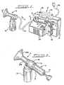
- the improved breast pump assembly illustrated herein includes two principal components.
- One is a manually operable breast pump, which is shown set up for manual operation in FIG. 2.
- the breast pump has a breast-hood assembly 10 and a hand-drivable piston pump 11 which connects to the breast-hood assembly in a manner which will be described in more detail hereafter.
- a container for the collection of breast milk, such as a bottle 12, is attached to the lower portion of the breast-hood assembly 10.
- the other principal component of the improved breast pump assembly is the motor drive unit 15 (e.g., FIGS. 1 and 5).
- the motor drive unit 15 is adapted to receive and hold the piston pump 11 when detached from the breast hood assembly 10, and to mechanically drive the piston pump 11.
- the motor drive unit 15 has an adaptor 16 which is attachable to a casing 17 of the drive unit (FIGS. 1, 3 and 3A).
- a piston cylinder 18 of the piston pump 11 is received in the adaptor 16.
- Piston rod 19 of the piston pump 11 is releasably held at one end of an arm 20, which is mounted at its other end to the casing 17.
- a motor driven mechanism is provided for cyclically turning the arm 20 through an arc to effect the reciprocating movement of the piston rod 19 and a piston 21 in a manner substantially similar to that of manually driving the piston rod 19.
- This drive mechanism will be described in more detail hereinafter, as will other aspects of this embodiment.
- a length of tubing 22 interconnects the adaptor 16 with the breast hood assembly 10 to communicate the negative pressure generated in the rearward stroke of the piston pump 11 for suction in the breast-hood assembly 10.
- the manually operable breast pump shown herein, and generally comprised of hood-assembly 10 and piston pump 11, is substantially the same as that shown in the aforementioned co-pending U.S. Patent Application Serial No. 07/053,055 which is incorporated herein by reference.
- that breast pump has a hood body or hood member having two ends.
- the first end 23a has a substantially wide cross-section (diameter), and is funnel-shaped.
- a second end 23b of the hood member constitutes a generally cylindrical extension of the funnel, and has a cross-section substantially narrower than the cross-section of the end 23a.
- the second end 23b communicates with a collecting or catch chamber 24 defined by a tubular extension 24a, and with a vacuum passage 25.
- the vacuum passage 25 also communicates with a vacuum line 26, which in this embodiment is defined by a short tubular extension or collar 50.
- a depending separation wall 27 forms a baffle between the end of the funnel portion 23b and the vacuum line 26, with the bottom of the separation wall 27 below the level of the vacuum line 26. Milk expressed into the hood member is thus blocked by the separation wall 27 from thereby entering the vacuum line 26.
- valve mechanism 28 At the lower portion of the collecting chamber 24 is a valve mechanism 28.
- the valve mechanism 28 uses a disk-member 29 as the valving member, with the disk 29 captured within a tubular-shape valve housing 30.
- the disk 29 When the breast pump is operated, the disk 29 is caused to move upwardly under vacuum where it contacts and seats against the bottom edge or lip of the tubular extension 24a forming the chamber 24, thus closing the collecting chamber 24.
- the vacuum is released, the disk 29 drops free from the foregoing seat, allowing milk collected in the collecting chamber 24 to flow downwardly into the container 12.
- the valve mechanism 28 is attached to the outside of the tubular extension 24a via a snug interference attachment.
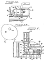
- the manually driven piston pump 11 (FIGS. 2 and 3) is connected to the breast-hood assembly 10 by connecting sleeve 31 (FIG. 4).
- Connecting sleeve 31 is internally screw-threaded, with the threads matched to the screw threads 32 formed on the forward end of the piston cylinder 18 (FIG. 3).
- the foward end of the piston cylinder 18 butts against a shoulder formed on the interior of the connecting sleeve 31 in a substantially air-tight fit.
- An aperture 35 is formed in the wall of the piston cylinder 18 at a point which corresponds to what is presently considered to be the maximum desired vacuum pressure to be reached on an average stroke of the piston pump 11. Once the head of the piston 21 passes beyond this aperture 35 in its vacuum-inducing stroke, the vacuum produced is automatically released.
- An adjustment mechanism for varying the amount of vacuum generated during pumping is also provided.
- This is represented in the illustrations by a ring 41 carried on the piston cylinder 18 adjacent its forward end, which overlies a pair of holes (not shown) through the cylinder 18.
- An interior chamber or channel (also not shown) is formed in the inside of the ring 41.
- the channel formed in the ring 41 has one or more openings that are opened to atmosphere.
- the ring 41 is preferably made out of a flexible or semi-flexible rubber-like material that enables a good seal to be maintained between the ring 41 and the piston cylinder 18.
- the ring 41 is rotated on the piston cylinder 18 to positions indicated as “Maximum.” “Medium”, and “Minimum” vacuum (see FIG. 3A).
- the range of vacuum is dependent upon the hole or holes in the cylinder 18 which fall within the area of the channel in the ring 41 when the ring is rotated.
- An adaptation to the breast pump described in the aforementioned patent application Serial No. 07/053,055 takes the form herein of a tubular extension or collar 50 formed in the upper part of the vacuum passage 25.
- a tubular connected 51 has one end 51a that is received in the collar 50 in a snug fit.
- the other end 51b of the connector fits within one end of the tubing 22 in a snug fit.
- this arrangement for connecting the tubing 22 to the vacuum passage 25 has advantages over the type of adapter used for an electric pump described in U.S. Serial No. 07/053,055, in that the connection of the tubing 22 is directly into the vacuum passage 25. While this direct connection is considered of increased advantage, the present invention can nevertheless be used successfully with the type of pump adapter shown in U.S. Serial No. 07/053,055, without any need to modify the breast-hood assembly shown therein.
- Piston cylinder 18 has its forward end screw threaded (at 32) for attachment to the connecting sleeve 31 of the hood assembly 10 for use in the manually driven mode.
- the adapter 16 is used.
- Adapter 16 has cap portion 52 which is match-threaded for substantially airtight attachment to the piston cylinder 18. Inside of the cap 52 (FIG. 3) is a small chamber 53 which communicates with the interior of the cap 52, and therefore also with the piston chamber. Extending off of the chamber 53 is a nipple-like outlet 54. Outlet 54 is sized to be received within the other end of the tubing 22.
- the adaptor 16 has a rounded-off sidewall 55 which extends from the cap 52, and which gives the adaptor 16 a more pleasing appearance.
- a hollow post 56 is received within a post hole 57 (see FIG. 5) to mount the adaptor to the casing 17.
- the adaptor 16 is additionally fixed in place on the casing 17 through use of a flange 58 (FIG. 3A) extending from sidewall 55. With the post 56 fully inserted within the post hole 57, adaptor 16 can be rotated clockwise so that a portion of flange 58 slides into an enlarged slot 59 formed in the casing 17. Post 56 is secured in the post hole 57 in this manner for a firm connection of the adaptor 16 to the casing 17.
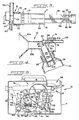
- piston rod 19 is received within a resilient U-shaped silicone grip or clamp 64 which is sized smaller than a necked-in portion 19a of piston rod 19.
- the piston rod necked-in portion 19a is forced into the resilient grip 64, which in turn tightly holds the piston rod to the arm 20.
- the grip 64 is pivotally attached to the U-shaped end of the arm (FIG. 3) through the use of a pair of opposed bosses 65 that are received in corresponding holes 66 formed in opposed lateral sides of the grip 64.
- the arm 20 has an I-beam type construction for strength and light weight.
- the lower end of the arm 20 is pivotally attached to the casing 17 via an elongated post 70 that extends through a hole 67 in the casing 17.
- the post 70 is fixed to the arm 20, and is rotatably mounted in a pair of tubular supports 68 formed on the casing floor. Also fixedly mounted to the post 70 is an interior arm 71.
- Interior arm 71 has a hard smooth bearing 73 mounted at its free upper end to bear against the outside edge of eccentric or cam 74.
- a metal rod 75 is attached at one end to the arm 71 via a pin 76 inserted radially through a hole in the rod 75, and received in a pair of opposed pin end receptacles 77 (V-shaped slots).
- a spring 78 is mounted concentric with rod 75.
- One end of the spring 78 is received on a button 83, which in turn fits within an opening provided in an inwardly extending flange 60.
- Flange 60 is turned from a metal mounting plate 61.
- Mounting plate 61 also carries the electrical connections for the drive mechanism, shown schematically at 62.
- the other end of the spring 78 bears against a disk 63 fixed to the free end of the rod 75.
- the spring 78 is loaded in this fashion to bias the arm 71 into constant engagement with the side edge of cam 74 (via bearing surface 73).
- cam 74 is eccentric, as previously noted, and has an edge surface 74a designed to impart movement to interior arm 71 to drive arm 20 in the desired pumping cycle.
- Cam 74 is mounted to the shaft 79 of a sprocket 80 (FIG. 5).
- Sprocket 80 is turned by a toothed drived belt 81 which is driven off of a reducing gear 82 mounted on a drive shaft 84.
- a wheel 85 is also mounted on drive shaft 84, and has a smooth surface on which smooth drive belt 86 is received.
- Drive belt 86 is in turn connected to a smooth small cylinder 88 which is fixed to drive a shaft 89 of a suitable drive motor 90.
- Motor 90 is turned on and off with toggle switch 91.
- a power cord 92 connects the motor to a power source.
- a suitable drive motor has been found by applicant to be a 12 v. dc. type motor for a battery driven power source, or an a.c. type motor for a motor operated off of residential current (110v).
- the drive mechanism should serve to reciprocate the piston pump 11 in a manner substantially the same as what is considered to be the optimum manual pumping cycle.
- Such an optimum cycle is considered at present to be a suction stroke which generates a maximum suction in the breast-hood in a range of about 250 mmHg at the top end, to no less then about 100 mmHg at the lower end. More suction than about 250 mmHg could result in discomfort or injury, and less than about 100 mmHg may not effect efficient milk expression.
- a suction stroke of approximately 50-60 cycles/min. is also considered desirable with 50 cycles/min. presently preferred.
- the preferred optimum cycle is illustrated below. It is designed to duplicate the same suction pattern as a suckling baby -- a regular, rhythmic series of cycles each consisting of suction, release and relaxation.
- the surface 74a of cam 74 is designed to reproduce this optimum cycle in driving the arm 71.
- the mechanism used to obtain this optimum stroke and suction may obviously vary with the type of piston pump and hood assembly being utilized, with the mechanism described herein being particularly adapted for use with the piston pump and breast hood described.
- Casing 17 encloses the drive mechanism and serves as a mount for the various elements of the drive mechanism.
- the casing 17 further includes a handy carrying handle 95. Vents 96 provide air inlets for a cooling fan (not shown) associated with the motor 90.
- a well 98 is also formed in the top of the casing 17, within which the bottle 12 can be temporarily held for convenience.
Landscapes
- Health & Medical Sciences (AREA)
- Heart & Thoracic Surgery (AREA)
- Animal Behavior & Ethology (AREA)
- General Health & Medical Sciences (AREA)
- Anesthesiology (AREA)
- Biomedical Technology (AREA)
- Hematology (AREA)
- Life Sciences & Earth Sciences (AREA)
- Vascular Medicine (AREA)
- Engineering & Computer Science (AREA)
- Public Health (AREA)
- Veterinary Medicine (AREA)
- Pediatric Medicine (AREA)
- External Artificial Organs (AREA)
- Details Of Reciprocating Pumps (AREA)
- Compressors, Vaccum Pumps And Other Relevant Systems (AREA)
- Compressor (AREA)
Applications Claiming Priority (2)
| Application Number | Priority Date | Filing Date | Title |
|---|---|---|---|
| US162056 | 1988-02-29 | ||
| US07/162,056 US5007899A (en) | 1988-02-29 | 1988-02-29 | Drive unit adapted for use with manual piston pump |
Publications (3)
| Publication Number | Publication Date |
|---|---|
| EP0330845A2 true EP0330845A2 (de) | 1989-09-06 |
| EP0330845A3 EP0330845A3 (de) | 1991-01-02 |
| EP0330845B1 EP0330845B1 (de) | 1993-12-15 |
Family
ID=22583981
Family Applications (1)
| Application Number | Title | Priority Date | Filing Date |
|---|---|---|---|
| EP89101557A Expired - Lifetime EP0330845B1 (de) | 1988-02-29 | 1989-01-30 | Milchpumpe mit Motorantrieb zur Anwendung mit einer manuell betriebenen Kolbenpumpe |
Country Status (7)
| Country | Link |
|---|---|
| US (1) | US5007899A (de) |
| EP (1) | EP0330845B1 (de) |
| JP (1) | JP2776872B2 (de) |
| AU (1) | AU622150B2 (de) |
| CA (1) | CA1329085C (de) |
| DE (1) | DE68911336T2 (de) |
| HK (1) | HK1001226A1 (de) |
Cited By (11)
| Publication number | Priority date | Publication date | Assignee | Title |
|---|---|---|---|---|
| EP0611578A1 (de) * | 1993-02-19 | 1994-08-24 | Neovation Ag | Medizintechnische Pumpe |
| US5676525A (en) * | 1993-02-19 | 1997-10-14 | Neovation Ag | Vacuum limiting medical pump |
| EP0875257A1 (de) * | 1997-04-29 | 1998-11-04 | Medela AG | Kolbenpumpe für Brustabsaugeinrichtung |
| WO2001034226A1 (de) | 1999-11-11 | 2001-05-17 | Kaweco Gmbh | Milchabsaugpumpe |
| DE10132516A1 (de) * | 2001-07-09 | 2003-01-30 | Kaweco Gmbh | Milchabsaugpumpe |
| EP1457217A1 (de) * | 2003-03-14 | 2004-09-15 | ARTSANA S.p.A. | Elektrisch angetriebene Muttermilchpumpe für den persönlichen Gebrauch |
| US6808517B2 (en) | 1999-12-10 | 2004-10-26 | Medela Holding Ag | Suction sequences for a breastpump |
| EP2218468A3 (de) * | 1999-12-10 | 2010-12-22 | Medela Holding AG | Programmierbare Brustpumpe |
| US8262606B2 (en) | 1999-12-10 | 2012-09-11 | Medela Holding Ag | Breastpump with stimulation and method |
| EP2745858A1 (de) * | 2012-12-21 | 2014-06-25 | Wen Ching Lee | Heimpflegesaugvorrichtung |
| EP1263487B2 (de) † | 1999-12-10 | 2016-11-23 | Medela Holding AG | Programmierbare Brustpumpe |
Families Citing this family (84)
| Publication number | Priority date | Publication date | Assignee | Title |
|---|---|---|---|---|
| US5308321A (en) * | 1992-05-05 | 1994-05-03 | Castro Donna J | Retainer assisted by vacuum expansion system |
| US5542921A (en) * | 1994-11-04 | 1996-08-06 | Gerber Products Company | Electric breast pump |
| US5571084A (en) * | 1994-12-12 | 1996-11-05 | Spread Spectrum Inc. | Microprocessor-controlled vested lactation system |
| US5601531A (en) * | 1995-02-16 | 1997-02-11 | Medela, Incorporated | Breast pump assembly and method of using same |
| WO1996034638A1 (en) | 1995-05-02 | 1996-11-07 | Medela, Inc. | Foot-powered breastmilk pump with removable piston pump |
| CH688811A5 (de) * | 1995-05-26 | 1998-04-15 | Trimed Ag | Muttermilchpumpe. |
| JP3744570B2 (ja) * | 1995-07-31 | 2006-02-15 | ピジョン株式会社 | 搾乳器 |
| US6547756B1 (en) | 1999-12-10 | 2003-04-15 | Medela Holding Ag | Programmable breastpump |
| US6257847B1 (en) | 1995-08-03 | 2001-07-10 | Medela, Inc. | Diaphragm pump and pump for double-breast pumping |
| US6481986B1 (en) | 1995-08-03 | 2002-11-19 | Medela Holding Ag | Vacuum adjustment mechanism particularly adapted for a breastpump |
| CH690956A5 (de) * | 1995-10-03 | 2001-03-15 | Trimed Ag | Regeleinrichtung, insbesondere für eine Muttermilchabsaugeinrichtung. |
| US5843029A (en) * | 1995-10-16 | 1998-12-01 | Gerber/Baby Care | Manual breast pump |
| US5720722A (en) * | 1996-01-11 | 1998-02-24 | Medela, Incorporated | Connector for use in single and double breast pumping and breast pump using same |
| USD383536S (en) * | 1996-04-08 | 1997-09-09 | Bachman Rebecca J | Manual breast pump |
| EP0800836B1 (de) * | 1996-04-14 | 2003-02-26 | Medela AG | Einrichtung zum Absaugen von Muttermilch |
| US6139521A (en) * | 1996-06-03 | 2000-10-31 | Medela Holding Ag | Breastpump having particular application as a small motorized pump capable of double-breast pumping |
| US5798266A (en) | 1996-08-27 | 1998-08-25 | K-Quay Enterprises, Llc | Methods and kits for obtaining and assaying mammary fluid samples for breast diseases, including cancer |
| US6110140A (en) | 1996-09-17 | 2000-08-29 | Medela, Inc. | Manual breastmilk pump |
| US6290671B1 (en) | 1996-10-03 | 2001-09-18 | Trimed Ag | Regulating device for a breast pump |
| US5941847A (en) * | 1998-02-06 | 1999-08-24 | Medela Holding Ag | Breast shield with vacuum isolation element |
| AU3328799A (en) | 1998-03-06 | 1999-09-20 | Ameda Ag Medical Equipment | Breast pump |
| US6090065A (en) * | 1998-07-06 | 2000-07-18 | Evenflo Company, Inc. | Self-cycling breast pump |
| US6045529A (en) * | 1998-10-02 | 2000-04-04 | Nuesch Logistik | Drive unit for a breastpump |
| US6328709B1 (en) | 1998-11-13 | 2001-12-11 | Pro Duct Health, Inc. | Devices and methods to identify ductal orifices during nipple aspiration |
| WO2000043550A2 (en) | 1999-01-21 | 2000-07-27 | Wayne State University | Method and apparatus for measuring factors in mammary fluids |
| US6964651B1 (en) * | 1999-06-23 | 2005-11-15 | L. Jason Clute | Apparatus for expressing milk |
| US7156301B1 (en) | 1999-09-07 | 2007-01-02 | American Express Travel Related Services Company, Inc. | Foldable non-traditionally-sized RF transaction card system and method |
| US7347360B2 (en) * | 2003-12-10 | 2008-03-25 | American Express Travel Related Services Company, Inc. | Foldable transaction card systems for non-traditionally-sized transaction cards |
| US7213764B2 (en) * | 2002-11-07 | 2007-05-08 | American Express Travel Related Services Company, Inc. | Foldable transaction card |
| US7837116B2 (en) | 1999-09-07 | 2010-11-23 | American Express Travel Related Services Company, Inc. | Transaction card |
| US7306158B2 (en) | 2001-07-10 | 2007-12-11 | American Express Travel Related Services Company, Inc. | Clear contactless card |
| US6673036B1 (en) | 1999-10-13 | 2004-01-06 | The First Years Inc. | Pumping breast milk |
| KR100371618B1 (ko) * | 2000-04-19 | 2003-02-11 | 서경득 | 유축기 |
| EP1163915A3 (de) * | 2000-06-12 | 2003-08-27 | Clute, Lorne Jason | Milchsaugeapparat |
| US6383164B1 (en) | 2000-09-26 | 2002-05-07 | Gerber Products Company | Massaging breast pump and funnel therefor |
| KR100390618B1 (ko) * | 2000-11-27 | 2003-07-12 | (주)서룡상사 | 모유 착유기 |
| JP2002336347A (ja) * | 2001-05-18 | 2002-11-26 | Univ Nihon | 搾乳器 |
| US20030073951A1 (en) * | 2001-05-30 | 2003-04-17 | Morton Kevin B. | Disposable patient interface for intraductal fluid aspiration system |
| US6866994B2 (en) * | 2001-05-30 | 2005-03-15 | Neomatrix, Llc | Noninvasive intraductal fluid diagnostic screen |
| US20040024352A1 (en) * | 2001-12-27 | 2004-02-05 | Playtex Products, Inc. | Breast pump system |
| KR20040071258A (ko) * | 2001-12-27 | 2004-08-11 | 플레이텍스 프로덕츠, 인크. | 유축기 시스템 |
| US6974440B2 (en) | 2002-04-04 | 2005-12-13 | Medela Holding Ag | Breastpump with compliant feature |
| US6749582B2 (en) | 2002-04-30 | 2004-06-15 | The First Years Inc. | Pumping breast milk |
| CA2492792C (en) * | 2002-07-19 | 2011-10-04 | Medela Holding Ag | Connector device |
| US7357782B2 (en) * | 2002-07-19 | 2008-04-15 | Roellin Richard | Connector device |
| US7540426B1 (en) | 2002-11-07 | 2009-06-02 | American Express Travel Related Services Company, Inc. | Foldable transaction cards and methods of making the same |
| US7137552B1 (en) | 2003-12-10 | 2006-11-21 | American Express Travel Related Services Company, Inc. | Portable electronic devices interconnected with convenient or foldable transaction cards |
| US7070095B1 (en) | 2002-11-07 | 2006-07-04 | American Express Travel Related Services Company, Inc. | Foldable transaction cards and methods of making the same |
| US7278584B1 (en) | 2002-11-07 | 2007-10-09 | American Express Travel Related Services Company, Inc. | Portable electronic music devices with convenient or foldable transaction cards |
| JP2006513071A (ja) * | 2002-12-11 | 2006-04-20 | アメリカン・エキスプレス・トラベル・リレイテッド・サービシズ・カンパニー・インコーポレーテッド | 折り畳み式トランザクションカードシステム |
| US20040127845A1 (en) * | 2002-12-27 | 2004-07-01 | Playtex Products, Inc. | Breast pump system |
| US20040158198A1 (en) * | 2003-02-10 | 2004-08-12 | Erich Pfenninger | Portable breast pump |
| GB2404590B (en) * | 2003-08-01 | 2005-06-01 | Cannon Rubber Ltd | Powered breast pump |
| US7776008B2 (en) * | 2003-08-08 | 2010-08-17 | Playtex Products, Inc. | Manual breast pump |
| US7721956B2 (en) * | 2003-12-10 | 2010-05-25 | American Express Travel Related Services Company, Inc. | Foldable transaction card systems |
| US7631812B2 (en) * | 2003-12-10 | 2009-12-15 | Williams Troy P | Foldable transaction card systems |
| US20050208271A1 (en) * | 2004-03-17 | 2005-09-22 | Fasching Rainer J | Bonding method for micro-structured polymers |
| CA2561854A1 (en) * | 2004-04-02 | 2005-10-20 | The Regents Of The University Of California | Device and systems for the intermittent drainage of urine and other biological fluids |
| US7396339B2 (en) * | 2004-04-30 | 2008-07-08 | The First Years Inc. | Pumping breast milk |
| US20060271019A1 (en) * | 2004-10-15 | 2006-11-30 | The Regents Of The University Of California | Drainage system |
| KR100629761B1 (ko) | 2005-01-27 | 2006-09-28 | 김상하 | 자동 유축기 |
| US7128021B1 (en) * | 2005-04-26 | 2006-10-31 | Peter Linda R | Mammal milking device |
| US20070135761A1 (en) * | 2005-12-09 | 2007-06-14 | Cheng Kai-Sheng | Breast pump |
| WO2007120622A2 (en) * | 2006-04-11 | 2007-10-25 | Playtex Products, Inc | Manual breast pump |
| US9162016B2 (en) * | 2006-09-22 | 2015-10-20 | Medela Holding Ag | Breastpump with irregular milk expression sequences |
| US20080139998A1 (en) | 2006-12-08 | 2008-06-12 | Medela Holding Ag | Breastpump Assemblies Having Silver-Containing Antimicrobial Compounds |
| US8070715B2 (en) | 2007-04-11 | 2011-12-06 | Medela Holding Ag | Method and apparatus for minimum negative pressure control, particularly for breastpump with breastshield pressure control system |
| US8070716B2 (en) * | 2007-04-11 | 2011-12-06 | Medela Holding Ag | Method and apparatus for minimum negative pressure control, particularly for a breastpump with breastshield pressure control system |
| JP5204533B2 (ja) * | 2008-04-04 | 2013-06-05 | ピジョン株式会社 | 搾乳器 |
| CA2742983A1 (en) * | 2008-11-07 | 2010-05-14 | Simplisse, Inc. | Breast pump |
| US8043255B2 (en) * | 2008-12-09 | 2011-10-25 | Weston Richard S | Chair powered breast pump apparatus |
| US8398584B2 (en) | 2009-01-16 | 2013-03-19 | Learning Curve Brands, Inc. | Breast pump and method of use |
| CN201375699Y (zh) * | 2009-02-15 | 2010-01-06 | 郭永峰 | 一种活塞式吸奶器 |
| GB0912229D0 (en) | 2009-07-14 | 2009-08-26 | Jackel Int Ltd | A breast pump |
| US9011372B2 (en) | 2010-07-22 | 2015-04-21 | Platinum Products Holding, Inc. | Manual breast pump with resilient return |
| EP2412392A1 (de) * | 2010-07-29 | 2012-02-01 | Koninklijke Philips Electronics N.V. | Kolbenpumpe mit verstellbarem Puffer |
| JP6255409B2 (ja) | 2012-09-24 | 2017-12-27 | コーニンクレッカ フィリップス エヌ ヴェKoninklijke Philips N.V. | 搾乳器システム |
| US9616156B2 (en) * | 2013-03-24 | 2017-04-11 | Naya Health, Inc. | Method, apparatus, and system for expression and quantification of human breast milk |
| ES2672339T3 (es) * | 2013-10-14 | 2018-06-13 | Vesucta Aps | Un dispositivo extractor de leche |
| WO2017030927A1 (en) | 2015-08-14 | 2017-02-23 | Medela Holding Ag | Mflp-valve for a pressure source |
| GB201808647D0 (en) * | 2015-11-13 | 2018-07-11 | Mitsubishi Heavy Ind Mach Systems Ltd | Communication control device, toll collection system, communication control,method and program |
| EP3865158A1 (de) | 2020-02-14 | 2021-08-18 | Medela Holding AG | Verfahren zum abpumpen von milch |
| USD976423S1 (en) * | 2021-10-14 | 2023-01-24 | Annabella Tech Ltd. | Breast pump for nursing mothers |
| USD1021065S1 (en) * | 2023-08-10 | 2024-04-02 | Shenzhen Lute Jiacheng Supply Chain Management Co., Ltd. | Breast pump funnel |
Citations (5)
| Publication number | Priority date | Publication date | Assignee | Title |
|---|---|---|---|---|
| US2222811A (en) * | 1937-08-16 | 1940-11-26 | Dinesen Laurits | Vacuum pressure pulsator |
| CH270694A (de) * | 1949-03-03 | 1950-09-15 | Mueller Ernst Kg | Pumpengerät. |
| EP0123269A2 (de) * | 1983-04-25 | 1984-10-31 | MEDAP Medizinische Apparate Alfred Horstmann Gesellschaft mit beschränkter Haftung | Frauenmilchpumpe |
| EP0162358A2 (de) * | 1984-05-25 | 1985-11-27 | KaWeCo GmbH Fabrik medizinischer Apparate | Muttermilchabsaugvorrichtung |
| DE8714995U1 (de) * | 1987-11-11 | 1987-12-23 | Richter, Siegfried, 7798 Pfullendorf | Muttermilch-Handpumpe |
Family Cites Families (8)
| Publication number | Priority date | Publication date | Assignee | Title |
|---|---|---|---|---|
| US1509226A (en) * | 1922-04-27 | 1924-09-23 | Earl D Brown | Breast pump |
| US1644257A (en) * | 1923-08-02 | 1927-10-04 | Lasker Edward | Breast pump |
| GB271857A (en) * | 1926-05-28 | 1927-10-27 | Louis Isaie Guillaume Sales | Improvements in or relating to breast pumps |
| US1966498A (en) * | 1933-05-04 | 1934-07-17 | Gross Louis | Fluid measuring and dispensing apparatus |
| US2419795A (en) * | 1945-07-11 | 1947-04-29 | Paul W Saunders | Breast pump |
| BE467414A (de) * | 1946-01-10 | |||
| US3993061A (en) * | 1975-02-28 | 1976-11-23 | Ivac Corporation | Syringe pump drive system and disposable syringe cartridge |
| JPS6294170A (ja) * | 1985-10-21 | 1987-04-30 | ピジヨン株式会社 | 搾乳器 |
-
1988
- 1988-02-29 US US07/162,056 patent/US5007899A/en not_active Expired - Lifetime
-
1989
- 1989-01-30 DE DE89101557T patent/DE68911336T2/de not_active Expired - Lifetime
- 1989-01-30 EP EP89101557A patent/EP0330845B1/de not_active Expired - Lifetime
- 1989-02-17 AU AU30089/89A patent/AU622150B2/en not_active Expired
- 1989-02-23 CA CA000591843A patent/CA1329085C/en not_active Expired - Lifetime
- 1989-02-28 JP JP1048425A patent/JP2776872B2/ja not_active Expired - Lifetime
-
1998
- 1998-01-13 HK HK98100247A patent/HK1001226A1/xx not_active IP Right Cessation
Patent Citations (5)
| Publication number | Priority date | Publication date | Assignee | Title |
|---|---|---|---|---|
| US2222811A (en) * | 1937-08-16 | 1940-11-26 | Dinesen Laurits | Vacuum pressure pulsator |
| CH270694A (de) * | 1949-03-03 | 1950-09-15 | Mueller Ernst Kg | Pumpengerät. |
| EP0123269A2 (de) * | 1983-04-25 | 1984-10-31 | MEDAP Medizinische Apparate Alfred Horstmann Gesellschaft mit beschränkter Haftung | Frauenmilchpumpe |
| EP0162358A2 (de) * | 1984-05-25 | 1985-11-27 | KaWeCo GmbH Fabrik medizinischer Apparate | Muttermilchabsaugvorrichtung |
| DE8714995U1 (de) * | 1987-11-11 | 1987-12-23 | Richter, Siegfried, 7798 Pfullendorf | Muttermilch-Handpumpe |
Cited By (13)
| Publication number | Priority date | Publication date | Assignee | Title |
|---|---|---|---|---|
| EP0611578A1 (de) * | 1993-02-19 | 1994-08-24 | Neovation Ag | Medizintechnische Pumpe |
| US5676525A (en) * | 1993-02-19 | 1997-10-14 | Neovation Ag | Vacuum limiting medical pump |
| EP0875257A1 (de) * | 1997-04-29 | 1998-11-04 | Medela AG | Kolbenpumpe für Brustabsaugeinrichtung |
| WO2001034226A1 (de) | 1999-11-11 | 2001-05-17 | Kaweco Gmbh | Milchabsaugpumpe |
| US7267662B1 (en) | 1999-11-11 | 2007-09-11 | Kaweco Gmbh | Milk sucking pump |
| US6808517B2 (en) | 1999-12-10 | 2004-10-26 | Medela Holding Ag | Suction sequences for a breastpump |
| EP2218468A3 (de) * | 1999-12-10 | 2010-12-22 | Medela Holding AG | Programmierbare Brustpumpe |
| US8262606B2 (en) | 1999-12-10 | 2012-09-11 | Medela Holding Ag | Breastpump with stimulation and method |
| US9199017B2 (en) | 1999-12-10 | 2015-12-01 | Medela Holding Ag | Breastpump with letdown feature |
| EP1263487B2 (de) † | 1999-12-10 | 2016-11-23 | Medela Holding AG | Programmierbare Brustpumpe |
| DE10132516A1 (de) * | 2001-07-09 | 2003-01-30 | Kaweco Gmbh | Milchabsaugpumpe |
| EP1457217A1 (de) * | 2003-03-14 | 2004-09-15 | ARTSANA S.p.A. | Elektrisch angetriebene Muttermilchpumpe für den persönlichen Gebrauch |
| EP2745858A1 (de) * | 2012-12-21 | 2014-06-25 | Wen Ching Lee | Heimpflegesaugvorrichtung |
Also Published As
| Publication number | Publication date |
|---|---|
| AU622150B2 (en) | 1992-04-02 |
| JPH01317448A (ja) | 1989-12-22 |
| CA1329085C (en) | 1994-05-03 |
| EP0330845B1 (de) | 1993-12-15 |
| US5007899A (en) | 1991-04-16 |
| DE68911336D1 (de) | 1994-01-27 |
| EP0330845A3 (de) | 1991-01-02 |
| HK1001226A1 (en) | 1998-06-05 |
| DE68911336T2 (de) | 1994-04-07 |
| JP2776872B2 (ja) | 1998-07-16 |
| AU3008989A (en) | 1989-08-31 |
Similar Documents
| Publication | Publication Date | Title |
|---|---|---|
| EP0330845B1 (de) | Milchpumpe mit Motorantrieb zur Anwendung mit einer manuell betriebenen Kolbenpumpe | |
| US6652484B1 (en) | Foot-powered breastmilk pump with removable piston pump | |
| EP1498149B1 (de) | Membranbrustpumpe | |
| JP5007023B2 (ja) | 刺激特徴付きの手動搾乳器 | |
| CA2327111C (en) | Diaphragm pump and pump for double-breast pumping | |
| US6814576B2 (en) | Oral cavity cleaning device | |
| US20140171917A1 (en) | Breastpump with Letdown Feature | |
| JP3993928B2 (ja) | 吸引圧脈動式搾乳器 | |
| AU744370B2 (en) | Diaphragm pump useful in breast pumping | |
| AU744212B2 (en) | Diaphragm pump useful in breast pumping |
Legal Events
| Date | Code | Title | Description |
|---|---|---|---|
| PUAI | Public reference made under article 153(3) epc to a published international application that has entered the european phase |
Free format text: ORIGINAL CODE: 0009012 |
|
| AK | Designated contracting states |
Kind code of ref document: A2 Designated state(s): CH DE FR GB IT LI SE |
|
| PUAL | Search report despatched |
Free format text: ORIGINAL CODE: 0009013 |
|
| AK | Designated contracting states |
Kind code of ref document: A3 Designated state(s): CH DE FR GB IT LI SE |
|
| 17P | Request for examination filed |
Effective date: 19910626 |
|
| 17Q | First examination report despatched |
Effective date: 19921210 |
|
| GRAA | (expected) grant |
Free format text: ORIGINAL CODE: 0009210 |
|
| ITF | It: translation for a ep patent filed | ||
| AK | Designated contracting states |
Kind code of ref document: B1 Designated state(s): CH DE FR GB IT LI SE |
|
| REF | Corresponds to: |
Ref document number: 68911336 Country of ref document: DE Date of ref document: 19940127 |
|
| ET | Fr: translation filed | ||
| PLBE | No opposition filed within time limit |
Free format text: ORIGINAL CODE: 0009261 |
|
| STAA | Information on the status of an ep patent application or granted ep patent |
Free format text: STATUS: NO OPPOSITION FILED WITHIN TIME LIMIT |
|
| 26N | No opposition filed | ||
| EAL | Se: european patent in force in sweden |
Ref document number: 89101557.0 |
|
| REG | Reference to a national code |
Ref country code: GB Ref legal event code: 732E |
|
| REG | Reference to a national code |
Ref country code: CH Ref legal event code: PFA Free format text: ISG AG,ALPENSTRASSE 2,6300 ZUG (CH) TRANSFER- ISG AG,C/O MEDELA AG LAETTICHSTRASSE 4,6341 BAAR (CH) |
|
| REG | Reference to a national code |
Ref country code: CH Ref legal event code: PUE Owner name: ISG AG TRANSFER- MEDELA AG |
|
| REG | Reference to a national code |
Ref country code: FR Ref legal event code: CD Ref country code: FR Ref legal event code: TP |
|
| REG | Reference to a national code |
Ref country code: GB Ref legal event code: 732E |
|
| REG | Reference to a national code |
Ref country code: GB Ref legal event code: IF02 |
|
| REG | Reference to a national code |
Ref country code: CH Ref legal event code: NV Representative=s name: ISLER & PEDRAZZINI AG |
|
| PG25 | Lapsed in a contracting state [announced via postgrant information from national office to epo] |
Ref country code: IT Free format text: LAPSE BECAUSE OF NON-PAYMENT OF DUE FEES Effective date: 20050130 |
|
| REG | Reference to a national code |
Ref country code: CH Ref legal event code: PCAR Free format text: ISLER & PEDRAZZINI AG;POSTFACH 1772;8027 ZUERICH (CH) |
|
| PGFP | Annual fee paid to national office [announced via postgrant information from national office to epo] |
Ref country code: SE Payment date: 20071217 Year of fee payment: 20 |
|
| PGFP | Annual fee paid to national office [announced via postgrant information from national office to epo] |
Ref country code: FR Payment date: 20071210 Year of fee payment: 20 Ref country code: GB Payment date: 20071218 Year of fee payment: 20 |
|
| PGFP | Annual fee paid to national office [announced via postgrant information from national office to epo] |
Ref country code: DE Payment date: 20071213 Year of fee payment: 20 |
|
| PGFP | Annual fee paid to national office [announced via postgrant information from national office to epo] |
Ref country code: CH Payment date: 20080328 Year of fee payment: 20 |
|
| REG | Reference to a national code |
Ref country code: CH Ref legal event code: PL |
|
| REG | Reference to a national code |
Ref country code: GB Ref legal event code: PE20 Expiry date: 20090129 |
|
| EUG | Se: european patent has lapsed | ||
| PG25 | Lapsed in a contracting state [announced via postgrant information from national office to epo] |
Ref country code: GB Free format text: LAPSE BECAUSE OF EXPIRATION OF PROTECTION Effective date: 20090129 |
|
| PGFP | Annual fee paid to national office [announced via postgrant information from national office to epo] |
Ref country code: IT Payment date: 20071219 Year of fee payment: 20 |
|
| PGRI | Patent reinstated in contracting state [announced from national office to epo] |
Ref country code: IT Effective date: 20091201 |