EP0330178B1 - Satellitennachrichtübertragungssystem mit Vielfachzugriff und Ersatzzentralstation - Google Patents
Satellitennachrichtübertragungssystem mit Vielfachzugriff und Ersatzzentralstation Download PDFInfo
- Publication number
- EP0330178B1 EP0330178B1 EP89103087A EP89103087A EP0330178B1 EP 0330178 B1 EP0330178 B1 EP 0330178B1 EP 89103087 A EP89103087 A EP 89103087A EP 89103087 A EP89103087 A EP 89103087A EP 0330178 B1 EP0330178 B1 EP 0330178B1
- Authority
- EP
- European Patent Office
- Prior art keywords
- signal
- station
- timing
- broadcasting signal
- identifying
- Prior art date
- Legal status (The legal status is an assumption and is not a legal conclusion. Google has not performed a legal analysis and makes no representation as to the accuracy of the status listed.)
- Expired - Lifetime
Links
Images


Classifications
-
- H—ELECTRICITY
- H04—ELECTRIC COMMUNICATION TECHNIQUE
- H04B—TRANSMISSION
- H04B7/00—Radio transmission systems, i.e. using radiation field
- H04B7/14—Relay systems
- H04B7/15—Active relay systems
- H04B7/185—Space-based or airborne stations; Stations for satellite systems
- H04B7/18523—Satellite systems for providing broadcast service to terrestrial stations, i.e. broadcast satellite service
-
- H—ELECTRICITY
- H04—ELECTRIC COMMUNICATION TECHNIQUE
- H04L—TRANSMISSION OF DIGITAL INFORMATION, e.g. TELEGRAPHIC COMMUNICATION
- H04L1/00—Arrangements for detecting or preventing errors in the information received
- H04L1/22—Arrangements for detecting or preventing errors in the information received using redundant apparatus to increase reliability
Definitions
- the present invention relates to a time division multiple accessing satellite communication system.
- the time division multiple accessing satellite communication system has a common communication channel interconnecting a central station and a plurality of remote stations through a satellite transponder.
- the common communication channel is divided into frames each having a plurality of time slots of a length.
- the central station transmits a broadcasting signal to the satellite transponder as a transmitted signal.
- the broadcasting signal has control information including a timing signal for controlling the remote stations.
- Each of the remote stations receives the transmitted broadcasting signal through the satellite transponder as a received broadcasting signal and derives the control information and the timing signal from the received broadcasting signal.
- the remote station generates a slot timing based on the derived timing signal and transmits a packet signal to one of the time slots according to the control information at the slot timing generated.
- a reference is made to, for example, US-A- 4,736,371.
- FR-A- 2 111 113 discloses a TDM satellite communication system which switches a station to the reference station condition when a currently operative reference station abandone
- the broadcasting signal from the central station is important in the multiple accessing satellite communication system. If the remote stations cannot receive the broadcasting signal due to rain or local power fault in the area where the central station is located or due to fault of a transmitter in the central station, the remote station cannot obtain the control information so that the communication cannot be effected in the system.
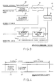
- the system shown therein comprises a central station 10, a plurality of remote stations 11, and a satellite transponder 12.
- the central station 10 comprises a plurality of station portions (two first and second ones are shown at 13 and 14) located at different areas on the earth, a central station controller 15 connected to the first and the second station portions 13 and 14.
- the central station controller 15 is for controlling the first and second station portions 13 and 14.
- the central station controller 15 delivers an enabling signal to a specific one of the first and the second station portions 13 and 14 so as to make the specific station portion operate as an operating station portion.
- the central station controller 15 also operates as a data processor for processing data received at the operating station portion as well as preparing data to be transmitted from the operating station portion.
- the first station portion 13 receives the enabling signal and serves as the operating station portion. Accordingly, the first station portion 13 carries out communication with the plurality of remote stations 12 by use of a common communication channel through the satellite transponder 11. That is, the first station portion 13 transmits a broadcasting signal which is, in turn, is received at the plurality of remote stations 12 through the satellite transponder 11. Each of the remote stations 12 transmits a packet signal at an appropriate time slot which is, in turn, received at the first station portion 13.
- the communicating state is shown by dashed lines in Fig. 1.
- the first station portion 13 produces a notifying signal when detecting fault of transmission of the broadcasting signal due to any reason as described above.
- the notifying signal is delivered to the central station controller 15.
- the central station controller 15 produces a stop or unable signal and delivers the unable signal to the first station portion 13 and, at the same time, delivers the enabling signal to the second station portion 14.
- the first station portion 13 stops its operation and the second station portion 14 starts and serves as the operating station portion and performs communication with the remote stations 12, as shown by dashed lines in Fig. 2.
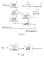
- each of the first and the second station portions 13 and 14 comprises an antenna 20 for transmitting/receiving a radio wave to and from the satellite transponder 11, an identifying (ID) number generator 21 for generating an ID number assigned to the same station, a broadcasting transmission signal generator 22 for multiplexing the ID number and the control information including the timing signal with the data to be transmitted in the time division fashion to produce the broadcasting signal, a transmitter 23 for transmitting the broadcasting signal through the antenna 20, a receiver 24 for receiving and processing a signal incoming through the antenna 20 to produce a received signal, and a transmission fault detector 25 responsive to the received signal for detecting, during transmission of the broadcasting signal to the remote stations, whether or not the broadcasting signal is transmitted normally to inform a detected result as the notifying signal to the central station controller 15.
- ID identifying
- broadcasting transmission signal generator 22 for multiplexing the ID number and the control information including the timing signal with the data to be transmitted in the time division fashion to produce the broadcasting signal
- a transmitter 23 for transmitting the broadcasting signal through the antenna
- the transmitter 23 is enabled or unabled in response to the enabling/unable signal from the central station controller 15.
- the central station controller 15 supplies to the operating station portion 13 or 14 the control information including the timing signal and the data to be transmitted.
- the control information and the data are multiplexed with the ID number at the broadcasting signal generator 22.
- the broadcasting signal has a format shown therein which comprises a control field 31 and the data field 32 as well known in the art.
- the data to be transmitted is inserted in the data field 32, while the control information and the ID number are inserted in the control field 31.
- the control field 31 comprises the timing signal portion 33 and the ID number portion 34.
- the control field 31 can be provided with other portions for other control data as known in the art.
- the broadcasting fault detector 25 comprises an ID number derive circuit 26 for deriving the ID number portion from the received signal and an ID number decision circuit 27 for deciding whether or not the derived ID number portion is representative of the own ID number of the own station portion.
- the broadcasting signal After being transmitted from the operating station portion 13 or 14, the broadcasting signal is repeated by the satellite transponder 11 and transmitted to the remote stations 12. Then, the repeated broadcasting signal is also transmitted to the central station 10. Therefore, in the operating station portion 13 or 14, the receiver 24 receives the broadcasting signal in the signal incoming through the antenna 20. Therefore, the received signal from the receiver 24 includes the broadcasting signal which is transmitted from and then received at the same operating station portion.
- the ID number derive circuit 26 derives the ID number portion 34 from the received signal and supplies the ID number to the ID number decision circuit 27.
- the ID number decision circuit 27 decides whether or not the supplied ID number coincides with the own ID number of the same station portion and delivers a decided signal to the central station controller 15 as the notifying signal. In other words, the broadcasting signal transmission is decided normal when the derived ID number coincides with the own ID number, while the transmission is decided false on non-coincidence.
- the broadcasting fault detector 26 can be formed to detect fault by use of response from remote stations.
- the operating station portion decides its own transmission false when receiving no signal from the remote stations in response to transmission of the broadcasting signal.
- a central station transmits a broadcasting signal including a request of correspondence of each of the remote stations for monitoring each remote station.
- the remote stations transmit monitoring correspondence signals to different time slots.
- the central station can decide the specific remote station false.
- the broadcasting fault detector 25 can be formed as a circuit for detecting no correspondence signal from all of the remote stations for the broadcasting signal.
- each of the remote stations 12 comprises an antenna 40 for transmitting/receiving a radio wave to or from the satellite transponder 11, a receiver 41 for receiving and processing the broadcasting signal which is transmitted from the operating station portion and incoming through the antenna 40 to produce a received broadcasting signal, a timing signal derive circuit 42 for deriving the timing signal from the received broadcasting signal to produce a derived timing signal, an ID number detector 43 for detecting the ID number in the received broadcasting signal to produce the detected ID number, a timing offset generator 44 for generating a timing offset corresponding to the derived ID number, and a slot timing generator 45 for generating the slot timing based on the derived timing signal and the generated timing offset.
- the timing offset generator 44 can be formed by combination of a timing offset memory 51 for memorizing a plurality of timing offset 5 values corresponding to the station portions, respectively, and a timing offset selector 52 responsive to the detected ID number for selecting a specific one of station portions which has the detected ID number to make the timing offset memory produce a specific one of the timing offset values corresponding to the specific station portion.
- the specific offset value is delivered to the slot timing generator 45.
- the remote station 12 further comprises a packet signal generator 46 for generating a packet signal from data or message supplied from a data terminal (not shown).
- the packet signal generator 46 sends out the packet signal to a transmitter 47 at the slot timing determined from the slot timing generator 45.
- the transmitter 47 transmits the packet signal through the antenna 40.
- each of the remote stations prepares at least one packet of the message of a predetermined time slot length and transmits the packet to a time slot at the slot timing.
- each remote station derives the timing signal from the received broadcasting signal.
- earth stations of the central station and the remote stations are disposed at different locations on the earth and, therefore, are different from each other in distance to the satellite transponder. Therefore, signals transmitted from the earth stations are different from each other in transmission time to the satellite transponder. Therefore, it is necessary to consider the signal transmission time from the earth stations to the satellite transponder in order to avoid a case where all of signals from the remote stations make radio interference at the satellite transponder.
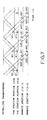
- Fig. 7 shows a state where remote stations 12-1 and 12-2 detect the timing signal transmitted from the operating station portion 13 or 14. Since there is a time difference between the transmission times from the satellite transponder 11 to the remote stations 12-1 and 12-2 because of distance difference, the detection time instant of the timing signal is different between the remote stations 12-1 and 12-2 for the same broadcasting signal transmission B1 or B2 from the operating station portion 13 or 14, as shown at D11 or D21 and D12 or D22.
- solid lines with arrows indicate a case where the first station portion 13 is the operating station portion while dashed lines with arrows indicate another case where the second station portion 14 operates as the operating station portion.
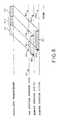
- the slot timing is prepared by direct use of the detected timing in the remote stations 12-1 and 12-2, and those remote stations transmit individual packet signals P1 and P2 to the same time slot at the prepared slot timing, those packets signals P1 and P2 are not completely superposed at the satellite transponder 11 but has a slip in time with a partial radio interference P12 as shown in Fig. 8 because of the time difference between the timing signal detection times D11 and D12 and because of the signal transmitting time difference from the remote stations 12-1 and 12-2 to the satellite transponder 11. This fact means that the slot timing is determined erroneously.
- each remote station determines the slot timing with a timing offset from the detection of the timing signal.
- the timing offset is determined according to the distance from the remote station itself to the satellite transponder 11.
- the slot timing is determined by consideration of the distance difference between each remote station 12-1 and 12-2 and the satellite transponder 11. That is, the slot timing is determined with a timing offset T1 from the timing signal detection D11 in the remote station 12-1, while with another timing offset T2 from the timing signal detection D12 in the remote station 12-2.
- the individual packet signals P1 and P2 are transmitted into different time slots at the slot timing with the timing offset T1 and T2 from the remote stations 12-1 12-2, respectively.
- the packet signals P1 and P2 are apart from each other on the time axis when arrived at the satellite transponder 11 as shown in Fig. 9. Accordingly, those packet signals are received at the first station portion 13 as shown in Fig. 9.
- the timing signal detection is also changed from D11 and D12 to D21 and D22 in both remote stations 12-1 and 12-2, respectively, as shown in Fig. 7.
- the slot timing is changed in each remote station so that the packet signals P1 and P2 are received at the second station portion 14 at a different timing from the previous receiving timing at the first station portion 13.
- the data reception timing at the central station controller 15 changes.
- the received data can not reliably be processed at the central station controller 15.
- the timing offset values T1 and T2 are changed to T1′ and T2′ at the remote stations 12-1 and 12-2, respectively.
- the packet signals P1 and P2 are transmitted from the remote stations 12-1 and 12-2 and are received at the second station portion 14 at a timing equal to that timing at which the first station portion 13 has received the signals.
- the change of the timing offset is performed by the ID number detector 43, the timing offset generator 44 and the slot timing generator 45 in the manner as described above in connection with Fig. 5 and 6.
Landscapes
- Engineering & Computer Science (AREA)
- Computer Networks & Wireless Communication (AREA)
- Signal Processing (AREA)
- Physics & Mathematics (AREA)
- Astronomy & Astrophysics (AREA)
- Aviation & Aerospace Engineering (AREA)
- General Physics & Mathematics (AREA)
- Radio Relay Systems (AREA)
- Time-Division Multiplex Systems (AREA)
Claims (6)
- Satellitennachrichtenübertragungssystem mit Vielfachzugriff mit einem gemeinsamen Nachrichtenübertragungskanal, der eine Zentralstation (10) und eine Vielzahl von Gegenstationen (12) über einen Satellitentransponder (11) verbindet, wobei der gemeinsame Nachrichtenübertragungskanal in Rahmen eingeteilt ist, wobei jeder eine vorbestimmte Anzahl von Zeitschlitzen aufweist, die Zentralstation (10) ein Rundfunksignal mit einem Taktsignal an die Gegenstationen (12) sendet und jede der Gegenstationen (12) das Rundfunksignal als ein Rundfunkempfangssignal empfängt und ein Paketsignal in einem der Zeitschlitze mit einem Schlitztakt auf der Grundlage des Taktsignals, das von dem Rundfunkempfangssignal abgeleitet ist, sendet;
wobei die Zentralstation (10) aufweist:
mehrere Stationsabschnitte (13, 14), die an verschiedenen Orten installiert sind und denen Identifikationsnummern zugeordnet sind, wobei einer der Stationsabschnitte (13, 14) selektiv mittels eines Freigabesignals die Erlaubnis erhält, als Betriebsstationsabschnitt zu arbeiten, um das Rundfunksignal zu senden; und
eine Zentralstationssteuereinrichtung (15), die mit den mehreren Stationsabschnitten (13, 14) verbunden ist, zum Steuern der Stationsabschnitte (13, 14), um das Freigabesignal an einen bestimmten der Stationsabschnitte (13, 14) zu übergeben, wobei die Zentralstationssteuereinrichtung (15) anspricht auf ein Benachrichtigungssignal von dem bestimmten Stationsabschnitt (13, 14), der gegenwärtig als der Betriebsstationsabschnitt (13, 14) arbeitet, zum Abgeben eines Sperrsignals an den bestimmten Stationsabschnitt (13, 14) und des Freigabesignals an einen anderen der Stationsabschnitte (13, 14);
wobei jeder der Stationsabschnitte (13, 14) aufweist:
eine Identifikationsnummernerzeugungseinrichtung (21) zum Erzeugen der eigenen der Identifikationsnummern;
eine Signalerzeugungseinrichtung (22) zum Erzeugen des Rundfunksignals mit dem Taktsignal und einem Identifikationsabschnitt, wobei die eigene Identifikationsnummer in den Identfikationsabschnitt eingefügt wird:
eine Sendeeinrichtung (23), die durch das Freigabesignal freigegeben wird, zum Senden des Rundfunksignals als Rundfunksendesignal;
eine Empfangseinrichtung (24) zum Empfangen eines Signals, das über eine Antenne ankommt, um ein Empfangssignal zu erzeugen; und
eine Fehlerentscheidungseinrichtung (25), die anspricht auf das Empfangssignal zum Entscheiden, ob die Übertragung des Rundfunksignals normal ausgeführt worden ist, um das Benachrichtigungssignal zu erzeugen, wenn entschieden worden ist, daß die Übertragung des Rundfunksignals fehlerhaft war;
wobei jede der Gegenstationen (12) aufweist:
eine Ermittlungseinrichtung (43) zum Ermitteln der Identifikationsnummer in dem Rundfunkempfangssignal als ermittelte Identifikationsnummer;
eine Versatzerzeugungseinrichtung (44), die anspricht auf die ermittelte Identifikationsnummer zum Erzeugen eines Zeitversatzes entsprechend der ermittelten Identifikationsnummer; und
eine Schlitztakterzeugungseinrichtung (45), die anspricht auf den Zeitversatz, zum Erzeugen des Zeitschlitztaktes, der von dem abgeleiteten Taktsignal und dem Zeitversatz bestimmt wird. - Satellitennachrichtenübertragungssystem mit Vielfachzugriff nach Anspruch 1, bei dem die Fehlerentscheidungseinrichtung (25) aufweist:
eine Ableitungseinrichtung (26), die anspricht auf das Empfangssignal zum Ableiten des Identifikationsabschnitts aus dem Empfangssignal als abgeleiteten Abschnitt; und
eine Entscheidungseinrichtung (27), die anspricht auf den abgeleiteten Abschnitt, zum Entscheiden, daß die eigene Identifikationsnummer in dem abgeleiteten Abschnitt nicht vorhanden ist, um das Benachrichtigungssignal zu erzeugen, das die Abwesenheit der eigenen Identifikationsnummer darstellt. - Zentralstation zur Verwendung in einem Satellitennachrichtenübertragungssystem mit Vielfachzugriff nach Anspruch 1 oder 2, mit einem gemeinsamen Nachrichtenübertragungskanal, der die Zentralstation (10) und mehrere Gegenstationen (12) über einen Satellitentransponder (11) verbindet, wobei der gemeinsame Nachrichtenübertragungskanal in Rahmen eingeteilt wird, wobei jeder eine vorbestimmte Anzahl von Zeitschlitzen aufweist, wobei die Zentralstation (10) ein Rundfunksignal mit einem Taktsignal an die Gegenstationen (12) sendet und jede der Gegenstationen (12) das Rundfunksignal als Rundfunkempfangssignal empfängt und ein Paketsignal in einem der Zeitschlitze mit einem Schlitztakt auf der Grundlage des Taktsignals, das aus dem Rundfunkempfangssignal abgeleitet ist, sendet;
wobei die Zentralstation (10) aufweist:
mehrere Stationsabschnitte, die an verschiedenen Orten installiert sind und denen Identifikationsnummern zugeordnet sind, wobei ein Stationsabschnitt (13, 14) selektiv durch ein Freigabesignal die Erlaubnis erhält, als Betriebsstationsabschnitt zu arbeiten, um das Rundfunksignal zu senden;
eine Zentralstationssteuereinrichtung (15), die mit den mehreren Stationsabschnitten (13, 14) verbunden ist, zum Steuern der Stationsabschnitte (13, 14), um das Freigabesignal an einen bestimmten der Stationsabschnitte (13, 14) zu übergeben, wobei die Zentralstationssteuereinrichtung (15) anspricht auf ein Benachrichtigungssignal von dem bestimmten Stationsabschnitt (13, 14), der gegenwärtig als Betriebsstationsabschnitt (13, 14) arbeitet, zum Übergeben eines Sperrsignals an den bestimmten Stationsabschnitt (13, 14) und des Freigabesignals an einen anderen der Stationsabschnitte (13, 14);
wobei jeder der Stationsabschnitte (13, 14) aufweist:
eine Identifikationsnummernerzeugungseinrichtung (21) zum Erzeugen der eigenen der Identifikationsnummern;
eine Signalerzeugungseinrichtung (22) zum Erzeugen des Rundfunksignals mit dem Taktsignal und einem Identifikationsabschnitt, wobei die eigene Identifikationsnummer in den Identifikationsabschnitt eingefügt wird;
eine Sendeeinrichtung (23), die durch das Freigabesignal freigegeben wird, zum Senden des Rundfunksignals als Rundfunksendesignal;
eine Empfangseinrichtung (24) zum Empfangen eines Signals, das über eine Antenne ankommt, um ein Empfangssignal zu erzeugen; und
eine Fehlerentscheidungseinrichtung (25), die anspricht auf das Empfangssignal, zum Entscheiden, ob die Übertragung des Rundfunksignals normal ausgeführt worden ist, um das Benachrichtigungssignal zu erzeugen, wenn entschieden worden ist, daß die Übertragung des Rundfunksignals fehlerhaft war. - Zentralstation nach Anspruch 3, bei der die Fehlerentscheidungseinrichtung (25) aufweist:
eine Ableitungseinrichtung (26), die anspricht auf das Empfangssignal, zum Ableiten des Identifikationsabschnitts aus dem Empfangssignal als abgeleiteter Abschnitt; und
eine Entscheidungseinrichtung (27), die anspricht auf den abgeleiteten Abschnitt, zum Entscheiden, daß die eigene Identifikationsnummer in dem abgeleiteten Abschnitt nicht vorhanden ist, um das Benachrichtigungssignal zu erzeugen, das die Abwesenheit der eigenen Identifikationsnummer darstellt. - Gegenstation zur Verwendung als eine von mehreren Gegenstationen in einem Satellitennachrichtenübertragungssystem mit Vielfachzugriff nach Anspruch 1 oder 2, mit einem gemeinsamen Nachrichtenübertragungskanal, der eine Zentralstation (10) und die mehreren Gegenstationen (12) über einen Satellitentransponder (11) verbindet, wobei der gemeinsame Nachrichtenübertragungskanal in Rahmen eingeteilt wird, wobei jeder eine vorbestimmte Anzahl von Zeitschlitzen aufweist, wobei die Zentralstation (10) mehrere Stationsabschnitte (12) aufweist, die selektiv als Betriebsstationsabschnitt arbeiten, wobei der Betriebsstationsabschnitt (13, 14) ein Rundfunksignal mit einem Taktsignal und einem zugeordneten Identifikationssignal an die Gegenstationen (12) sendet, und jede der Gegenstationen (12) das Rundfunksignal als Rundfunkempfangssignal empfängt und ein Paketsignal in einem der Zeitschlitze mit einem Schlitztakt auf der Grundlage des Taktsignals, das aus dem Rundfunkempfangssignal abgeleitet ist, sendet;
wobei die Gegenstation (12) aufweist:
eine Ermittlungseinrichtung (43) zum Ermitteln der Identifikationsnummer in dem Rundfunkempfangssignal als ermittelte Identifikationsnummer;
eine Versatzerzeugungseinrichtung (44), die anspricht auf die ermittelte Identifikationsnummer, zum Erzeugen eines Zeitversatzes entsprechend der ermittelten Identifikationsnummer; und
eine Schlitztakterzeugungseinrichtung (45), die anspricht auf den Zeitversatz, zum Erzeugen des Schlitztaktes, der von dem abgeleiteten Taktsignal und dem Zeitversatz bestimmt wird. - Gegenstation nach Anspruch 5, bei der die Versatzerzeugungseinrichtung (44) aufweist:
eine Speichereinrichtung (51) zum Speichern mehrerer Zeitversatzwerte entsprechend der jeweiligen Stationsabschnitte (13, 14);
eine Wähleinrichtung (52), die anspricht auf die ermittelte Identifikationsnummer, zum Wählen als gewählten Wert eines der mehreren Zeitversatzwerte entsprechend dem einen der Stationsabschnitte (13, 14), der die ermittelte Identifikationsnummer aufweist, wobei die Wähleinrichtung (52) den gewählten Wert als den Zeitversatz erzeugt.
Applications Claiming Priority (2)
| Application Number | Priority Date | Filing Date | Title |
|---|---|---|---|
| JP40426/88 | 1988-02-23 | ||
| JP63040426A JPH0618337B2 (ja) | 1988-02-23 | 1988-02-23 | 衛星通信方式 |
Publications (3)
| Publication Number | Publication Date |
|---|---|
| EP0330178A2 EP0330178A2 (de) | 1989-08-30 |
| EP0330178A3 EP0330178A3 (de) | 1991-10-02 |
| EP0330178B1 true EP0330178B1 (de) | 1994-10-12 |
Family
ID=12580327
Family Applications (1)
| Application Number | Title | Priority Date | Filing Date |
|---|---|---|---|
| EP89103087A Expired - Lifetime EP0330178B1 (de) | 1988-02-23 | 1989-02-22 | Satellitennachrichtübertragungssystem mit Vielfachzugriff und Ersatzzentralstation |
Country Status (6)
| Country | Link |
|---|---|
| US (1) | US4947451A (de) |
| EP (1) | EP0330178B1 (de) |
| JP (1) | JPH0618337B2 (de) |
| AU (1) | AU610467B2 (de) |
| CA (1) | CA1301379C (de) |
| DE (1) | DE68918727T2 (de) |
Families Citing this family (24)
| Publication number | Priority date | Publication date | Assignee | Title |
|---|---|---|---|---|
| JP2595603B2 (ja) * | 1988-01-11 | 1997-04-02 | 日本電気株式会社 | 要求割付多元接続制御方式 |
| JPH0362630A (ja) * | 1989-07-31 | 1991-03-18 | Nec Eng Ltd | 衛星通信方式 |
| US5093958A (en) * | 1990-05-30 | 1992-03-10 | Lloyd Levine | Automobile floor mat anchoring system |
| JP3034282B2 (ja) * | 1990-07-12 | 2000-04-17 | 株式会社東芝 | 非同期型移動無線通信システム |
| NL9002401A (nl) * | 1990-11-05 | 1992-06-01 | Philips Nv | Kommunikatiesysteem en een centrale besturingseenheid en een kommunikatiepost in het kommunikatiesysteem. |
| GB9024684D0 (en) * | 1990-11-13 | 1991-01-02 | Cognito Group Ltd | A method of communicating data |
| US5291518A (en) * | 1991-09-06 | 1994-03-01 | Metriplex, Inc. | Link system for radio paging service |
| SE469543B (sv) * | 1991-12-12 | 1993-07-19 | Televerket | Anordning foer reservvaeg vid mobilt trunkerat telekommunikationssystem |
| CA2088753C (en) * | 1992-02-04 | 1999-02-16 | Tomoki Osawa | Point-to-multipoint communication network capable of retransmitting a multicast signal |
| US5613065A (en) * | 1992-02-19 | 1997-03-18 | Fujitsu Limited | Information broadcasting system having reception error minimizing facility |
| JPH0738612B2 (ja) * | 1992-03-18 | 1995-04-26 | 日本電気株式会社 | 衛星通信システムにおける制御装置 |
| JPH0738606B2 (ja) * | 1992-10-30 | 1995-04-26 | 日本電気株式会社 | 衛星通信方式 |
| US5499243A (en) * | 1993-01-22 | 1996-03-12 | Hall; Dennis R. | Method and apparatus for coordinating transfer of information between a base station and a plurality of radios |
| DE4308161C2 (de) * | 1993-03-16 | 2000-12-14 | Philips Corp Intellectual Pty | System zur Nachrichtenübertragung über Satelliten |
| JPH08251096A (ja) * | 1995-03-11 | 1996-09-27 | Nec Corp | スロット割り当て方式 |
| US5535191A (en) * | 1995-06-28 | 1996-07-09 | Seiko Communications Systems, Inc. | Method and apparatus for switching between redundant hardware in a wireless data communication system |
| DE19728061C2 (de) * | 1997-07-01 | 2002-10-24 | Deutsche Telekom Ag | Verfahren zur Steuerung der Nutzung von Satelliten-Übertragungskapazität zum Ersetzen gestörter Datenleitungen in terrestrischen Netzen und Schaltungsanordnung zur Durchführung des Verfahrens |
| EP1052789A1 (de) * | 1999-05-13 | 2000-11-15 | ICO Services Ltd. | Mobiles Satelliten Telefon System mit Packet Funk Dienst |
| US6113075A (en) * | 1999-07-06 | 2000-09-05 | Mcmichael; Thomas James | Scissors type apparatus for removing floor coverings |
| US6553009B2 (en) * | 1999-07-09 | 2003-04-22 | Satellite-Smart Solutions Ltd. | Direct satellite communication |
| GB2369538B (en) * | 2000-11-24 | 2004-06-30 | Ibm | Recovery following process or system failure |
| US8027285B1 (en) * | 2007-06-15 | 2011-09-27 | Vt Idirect, Inc. | Method to eliminate frequency offset introduced in a network |
| US8068448B1 (en) * | 2007-06-15 | 2011-11-29 | Vt Idirect, Inc. | Apparatus, system, and computer program for synchronizing communications |
| US9680199B2 (en) * | 2014-06-27 | 2017-06-13 | Viasat, Inc. | System and apparatus for driving antenna |
Citations (2)
| Publication number | Priority date | Publication date | Assignee | Title |
|---|---|---|---|---|
| US4736371A (en) * | 1985-12-30 | 1988-04-05 | Nec Corporation | Satellite communications system with random multiple access and time slot reservation |
| JPS6387838A (ja) * | 1986-09-30 | 1988-04-19 | Nec Corp | 通信ネツトワ−クにおける監視方式 |
Family Cites Families (5)
| Publication number | Priority date | Publication date | Assignee | Title |
|---|---|---|---|---|
| CH541259A (it) * | 1970-12-17 | 1973-08-31 | Sits Soc It Telecom Siemens | Sistema di trasmissione a divisione di tempo per comunicazione via satellite comprendente una pluralità di stazioni a terra |
| US4224538A (en) * | 1978-09-15 | 1980-09-23 | Firetek Corporation | Series supervision/parallel actuation device |
| US4617674A (en) * | 1983-07-14 | 1986-10-14 | Rca Corporation | Synchronizing system for spread spectrum transmissions between small earth stations by satellite via an intermediate hop to a large earth station |
| US4656619A (en) * | 1984-04-16 | 1987-04-07 | Nec Corporation | Supervising and controlling system for a communication station in a TDMA communication system |
| JPS61120538A (ja) * | 1984-11-15 | 1986-06-07 | Nec Corp | 多方向多重通信装置 |
-
1988
- 1988-02-23 JP JP63040426A patent/JPH0618337B2/ja not_active Expired - Lifetime
-
1989
- 1989-02-22 DE DE68918727T patent/DE68918727T2/de not_active Expired - Fee Related
- 1989-02-22 CA CA000591715A patent/CA1301379C/en not_active Expired - Lifetime
- 1989-02-22 US US07/314,047 patent/US4947451A/en not_active Expired - Fee Related
- 1989-02-22 EP EP89103087A patent/EP0330178B1/de not_active Expired - Lifetime
- 1989-02-23 AU AU30261/89A patent/AU610467B2/en not_active Ceased
Patent Citations (2)
| Publication number | Priority date | Publication date | Assignee | Title |
|---|---|---|---|---|
| US4736371A (en) * | 1985-12-30 | 1988-04-05 | Nec Corporation | Satellite communications system with random multiple access and time slot reservation |
| JPS6387838A (ja) * | 1986-09-30 | 1988-04-19 | Nec Corp | 通信ネツトワ−クにおける監視方式 |
Also Published As
| Publication number | Publication date |
|---|---|
| JPH0618337B2 (ja) | 1994-03-09 |
| AU610467B2 (en) | 1991-05-16 |
| DE68918727D1 (de) | 1994-11-17 |
| DE68918727T2 (de) | 1995-02-16 |
| JPH01215133A (ja) | 1989-08-29 |
| AU3026189A (en) | 1989-08-24 |
| CA1301379C (en) | 1992-05-19 |
| EP0330178A3 (de) | 1991-10-02 |
| US4947451A (en) | 1990-08-07 |
| EP0330178A2 (de) | 1989-08-30 |
Similar Documents
| Publication | Publication Date | Title |
|---|---|---|
| EP0330178B1 (de) | Satellitennachrichtübertragungssystem mit Vielfachzugriff und Ersatzzentralstation | |
| EP0263421B1 (de) | Mehrpunkt-Datenübertragung mit Überwachungssystem zum Erkennen von gestörten Aussenstellen | |
| US5621735A (en) | Adaptive time-division multiplexing communications protocol method and system | |
| US4930118A (en) | Frame-interval fault detection in a demand assignment TDMA communication system | |
| EP0269120B1 (de) | TDMA-Übertragungssystem mit gemeinsamen Zeitschlitzen für Systemwartung | |
| US4506357A (en) | Method and apparatus for switching loop type transmission lines | |
| US4446551A (en) | Data highway system with dual transmitting loop lines | |
| US5448766A (en) | Method and apparatus for automatically replacing a non-functioning transmitter in a radio communication system | |
| US6084863A (en) | Method and system for controlling a radio communication repeater | |
| US4597079A (en) | Redundant switchover system for TDMA satellite communication equipment | |
| EP0883943B1 (de) | Verfahren und einrichtung zum umschalten zwischen redundanter hardware in einem drahtlosen datenübertragungssystem | |
| EP1009116B1 (de) | Schnurloses Netzwerk und Verfahren zur Herstellung der Zeitsynchronisation unter einer Vielzahl von Bussen | |
| CA1254313A (en) | Station of a tdma communication network capable of quickly changing communication traffic without causing an overlap between transmission bursts | |
| EP0214333B1 (de) | Kanalüberwachungsschaltung zur Verwendung in einer Relaisstelle eines numerischen Funkbandübertragungssystems | |
| US5437059A (en) | Radio transmitting system having back-up radio receiver operable in response to failure of main feed line | |
| EP0459325B1 (de) | Mehrpunktkommunikationssystem | |
| EP0720325B1 (de) | System zur Gewinnung eines gewünschten Trägers aus einem FDM-Signal | |
| US5375252A (en) | Paging radio communications system and method | |
| US6931443B1 (en) | Data communication system | |
| US5448588A (en) | Data transmission circuit capable of avoiding repeated reception and transmission of an identical transmission signal | |
| JP2591727B2 (ja) | Tdma送信バースト制御方式 | |
| JP2812092B2 (ja) | 時分割多元接続無線装置 | |
| JPS60214132A (ja) | 地理的切替え方式 | |
| JPS6086947A (ja) | 遠隔監視制御装置におけるボ−リング方式 | |
| JPH0817362B2 (ja) | 子局異常検出方式 |
Legal Events
| Date | Code | Title | Description |
|---|---|---|---|
| PUAI | Public reference made under article 153(3) epc to a published international application that has entered the european phase |
Free format text: ORIGINAL CODE: 0009012 |
|
| 17P | Request for examination filed |
Effective date: 19890222 |
|
| AK | Designated contracting states |
Kind code of ref document: A2 Designated state(s): DE FR GB |
|
| PUAL | Search report despatched |
Free format text: ORIGINAL CODE: 0009013 |
|
| AK | Designated contracting states |
Kind code of ref document: A3 Designated state(s): DE FR GB |
|
| 17Q | First examination report despatched |
Effective date: 19930419 |
|
| GRAA | (expected) grant |
Free format text: ORIGINAL CODE: 0009210 |
|
| AK | Designated contracting states |
Kind code of ref document: B1 Designated state(s): DE FR GB |
|
| REF | Corresponds to: |
Ref document number: 68918727 Country of ref document: DE Date of ref document: 19941117 |
|
| ET | Fr: translation filed | ||
| PLBE | No opposition filed within time limit |
Free format text: ORIGINAL CODE: 0009261 |
|
| STAA | Information on the status of an ep patent application or granted ep patent |
Free format text: STATUS: NO OPPOSITION FILED WITHIN TIME LIMIT |
|
| 26N | No opposition filed | ||
| PGFP | Annual fee paid to national office [announced via postgrant information from national office to epo] |
Ref country code: DE Payment date: 20010212 Year of fee payment: 13 |
|
| PGFP | Annual fee paid to national office [announced via postgrant information from national office to epo] |
Ref country code: FR Payment date: 20010213 Year of fee payment: 13 |
|
| PGFP | Annual fee paid to national office [announced via postgrant information from national office to epo] |
Ref country code: GB Payment date: 20010221 Year of fee payment: 13 |
|
| REG | Reference to a national code |
Ref country code: GB Ref legal event code: IF02 |
|
| PG25 | Lapsed in a contracting state [announced via postgrant information from national office to epo] |
Ref country code: GB Free format text: LAPSE BECAUSE OF NON-PAYMENT OF DUE FEES Effective date: 20020222 |
|
| PG25 | Lapsed in a contracting state [announced via postgrant information from national office to epo] |
Ref country code: DE Free format text: LAPSE BECAUSE OF NON-PAYMENT OF DUE FEES Effective date: 20020903 |
|
| GBPC | Gb: european patent ceased through non-payment of renewal fee |
Effective date: 20020222 |
|
| PG25 | Lapsed in a contracting state [announced via postgrant information from national office to epo] |
Ref country code: FR Free format text: LAPSE BECAUSE OF NON-PAYMENT OF DUE FEES Effective date: 20021031 |
|
| REG | Reference to a national code |
Ref country code: FR Ref legal event code: ST |