EP0329892A2 - Système d'affichage comportant un mécanisme pour fenêtres - Google Patents
Système d'affichage comportant un mécanisme pour fenêtres Download PDFInfo
- Publication number
- EP0329892A2 EP0329892A2 EP88310189A EP88310189A EP0329892A2 EP 0329892 A2 EP0329892 A2 EP 0329892A2 EP 88310189 A EP88310189 A EP 88310189A EP 88310189 A EP88310189 A EP 88310189A EP 0329892 A2 EP0329892 A2 EP 0329892A2
- Authority
- EP
- European Patent Office
- Prior art keywords
- window
- display
- range
- display buffer
- values
- Prior art date
- Legal status (The legal status is an assumption and is not a legal conclusion. Google has not performed a legal analysis and makes no representation as to the accuracy of the status listed.)
- Granted
Links
Images


Classifications
-
- G—PHYSICS
- G09—EDUCATION; CRYPTOGRAPHY; DISPLAY; ADVERTISING; SEALS
- G09G—ARRANGEMENTS OR CIRCUITS FOR CONTROL OF INDICATING DEVICES USING STATIC MEANS TO PRESENT VARIABLE INFORMATION
- G09G5/00—Control arrangements or circuits for visual indicators common to cathode-ray tube indicators and other visual indicators
- G09G5/14—Display of multiple viewports
-
- G—PHYSICS
- G09—EDUCATION; CRYPTOGRAPHY; DISPLAY; ADVERTISING; SEALS
- G09G—ARRANGEMENTS OR CIRCUITS FOR CONTROL OF INDICATING DEVICES USING STATIC MEANS TO PRESENT VARIABLE INFORMATION
- G09G5/00—Control arrangements or circuits for visual indicators common to cathode-ray tube indicators and other visual indicators
- G09G5/02—Control arrangements or circuits for visual indicators common to cathode-ray tube indicators and other visual indicators characterised by the way in which colour is displayed
- G09G5/06—Control arrangements or circuits for visual indicators common to cathode-ray tube indicators and other visual indicators characterised by the way in which colour is displayed using colour palettes, e.g. look-up tables
Definitions
- the present invention relates to a display system comprising a windowing mechanism.
- Windowing is a technique whereby a display field (eg. a display screen) may be shared by a number of tasks by allowing a portion of the display to be allocated to each of the tasks. Often, the windows overlap one another which creates problems for the display system in determining which information received from the tasks is to be displayed at which position in the display field.
- a display field eg. a display screen
- information relating to each pixel position in the display field is stored in a display buffer.
- the information for a particular pixel position in the display field identifies the colour for the pixel at that position.
- This information can be used to drive a display device directly, or can instead be used to index a look-up table containing information for actually driving the display device.
- the look-up table, or palette as it is usually known, can be compared to an artist's palette, as each location, or entry, in the palette defines a particular colour mix.
- the index information need not necessarily be colour information but could, for example, be grey - scale information for a monochrome display.
- the palette defines the chrominance and/or luminance values for the pixels of the display field.
- the most widely used windowing technique is for control software to work out for each line, area or character to be displayed whether it falls totally, partly or not at all within a window in the display field and can therefore be displayed. This is a time consuming process and has severe performance disadvantages, particularly for an inter active display system.
- the palette is provided as a common system resource for a number of tasks, if any of the tasks alters an entry in the palette, then this entry will also be changed for the other tasks.
- One such approach is to allocate one or more bit planes (ie. one or more bits per pixel location) to each window and using a plane write enable mask (a mask saying which bits in each pixel are to be updated) to protect planes belonging to anything but the current window. It is possible to arrange a plurality of windows in a priority order by manipulating the palette. However, this severely limits the number of colours available. If there are eight bits per pixel (ie. for an 8 plane machine) and four windows, then only four colours can be allocated per window. Palette control is also difficult in such an arrangement as all the windows are associated with bits in each palette entry. In view of this, when a task wishes to change one of its colours, multiple palette entries have to be modified.
- a window is defined in hardware which may be updated regardless of the display field contents and the data to be written.
- This technique is relatively efficient for drawing a single rectangular window, it becomes increasing inefficient as more windows are included and particularly so where windows are overlaid by others leaving non-rectangular areas visible, in which case a scissor plane is required to define the scissor boundary.
- a further windowing technique for display systems with a display device in the form of a cathode ray tube (CRT), is the use of a cathode ray tube controller (CRTC) to pick up an appropriate window for display pixel by pixel from separate sources (essentially separate display buffers), one per window.
- CTR cathode ray tube controller
- CRTC cathode ray tube controller
- a display system which is generally of this type and comprises a multi-plane display buffer in which windowing is performed using an additional bit plane for selecting the source of data to be displayed, is described in an article on pages 2526 and 2527 of the IBM Technical Disclosure Bulletin, Vol 29, No 6 published in November 1986.
- the present invention is directed to a display system of the type which comprises a palette for chrominance and/or luminance information, a display buffer for pixel information defining the pixels of a display field, the pixel information including index values for indexing the palette (ie. for addressing entries in the palette) to select the chrominance and/or luminance of the pixels.
- An object of the invention is to provide such a display system with a windowing mechanism which mitigates the problems of the prior art approaches.
- the present invention provides a display system comprising a palette for chrominance and/or luminance information, a display buffer for pixel information defining the pixels of a display field, the pixel information including index values for indexing the palette to select the chrominance and/or luminance of the pixels, and a windowing mechanism for associating a different range of index values with each of a plurality of windows and for responding to index values stored at individual pixel positions in the display buffer to determine the visible extent of a given window within the display field.
- the windowing mechanism is able to allow a plurality of windows to be displayed with a minimum of extra logic and without unduly constraining the choice of chrominance and/or luminance (hereinafter, for conciseness, referred to as "colours") of pixels within those windows.
- the number of different colours available in each window will depend on the number of windows to be displayed, but each colour can be selected from the full set of colours which can be specified by the palette.
- a consequence of associating the ranges of palette index values to respective windows is that a colour within a window can be changed by modifying the content of the single palette entry indexed, or addressed by the appropriate index value.
- windows are rectangular in shape, although they may be overlapped by other windows to create more complicated shapes. However, as the visible extent of a window is determined, in the invention, from the index values stored at individual pixel locations in the display buffer, it does not matter if the shape of the visible part of a window is complicated. Moreover, if a display system in accordance with the invention includes means for initially defining windows of a non-rectangular shape such as a circle star, etc., these can be supported very effectively.
- the windowing mechanism comprises windowing logic for initialising a window by causing index values from the range of values associated with that window to be stored at all pixel positions for that window in the display buffer.
- the windowing logic is arranged to initialise a plurality of windows by storing the index values for each window in order of priority, starting with the lowest priority window, such that index values for a higher priority window overwrite index values previously stored in the display buffer for an overlapping part of a lower priority window. In this way, when the initialisation is complete, the index values remaining in the display buffer correspond to the visible parts of the windows only.
- the initialisation of the display buffer is only carried out infrequently, at system initialisation and when the configuration of the windows in the display field is changed.
- normal updating of the display buffer is performed by simply responding to index values stored at individual pixel positions in the display buffer to determine the visible extent of a given window within the display field. This means that even if the initialisation is complicated, due, for example, to a need to set up complicated window shapes and/or window overlays, this does not create a significant system overhead.
- the windowing mechanism preferably comprises a range comparator for comparing index values stored in the display buffer to the range of values associated with a given window.
- the windowing logic causes the range comparator to determine whether an existing index value stored at a pixel position in the display buffer for which an item of update information is destined falls within the range for the given window
- the windowing mechanism additionally comprises means responsive to the output of the range comparator to cause the item of update information to be stored at that pixel position in the display buffer if the comparison is positive and otherwise to cause the existing index value to be stored again in the display buffer at that pixel position.
- the range comparator comprises an upper bound comparator for determining whether an index value stored in the display buffer is less than or equal to an maximum index value of the range and lower bound comparator for determining whether that index value is greater than or equal to a minimum value of the range, and logic gate means for combining the output of the upper and lower bound comparators for determining whether that index value is within the range defined by the maximum and minimum values of the range.
- a maximum register and a minimum register are provided for the maximum and minimum values, respectively, of the range for the window currently being processed.
- the windowing logic is arranged to associate presentation spaces for the image data of processing tasks with respective windows.
- the windowing logic is preferably arranged to translate colour code values of image data in each of a plurality of said presentation spaces into appropriate index values within the respective ranges for the windows associated therewith.
- the windowing logic is preferably arranged to cause the maximum and minimum values associated with a given window to be stored in the maximum and minimum registers and subsequently to pass update information for the presentation space associated with that window for updating the display buffer.
- a presentation space is a virtual display buffer which is supported by the windowing logic.
- the IBM 8514/A graphics adapter (described in the IBM Personal System/2 Display Adapter 8514/A Technical Reference Manual) is a display system which comprises a palette for picture chrominance and/or luminance information and a buffer for pixel information defining the pixels of a display field, the pixel information including index values for indexing the palette to select the chrominance and/or luminance for the pixels.
- a colour comparison register and colour comparison logic are provided which allow the values stored in the display buffer to be compared to a given value.
- the colour comparison logic can be used to implement underpaint by setting the colour comparison register to the colour of the erased screen. This compares to the arrangement described in the TDB article mentioned in the last paragraph. There is no suggestion, however, of the colour comparison register and colour comparison logic being used to provide a windowing mechanism.
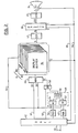
- FIG. 1 is a schematic block diagram of a display system in the form of a personal computer comprising a number of different system units connected via a system bus 12.
- the system bus comprises a data bus 14, an address bus 16 and a control bus 18.
- a microprocessor 10 random access memory 20
- keyboard adapter 28 a display adapter 32
- I/O adapter 22 The keyboard adapter is used to connect a keyboard 30 to the system bus.
- the display adapter connects the system bus to a display device 34.
- the I/O adapter likewise provides a connection between other input/output devices 24 (eg. DASDs) and the system bus.
- the personal computer may also be provided, as is shown, with a communications adapter 26 for allowing the personal computer to be connected to and to communicate with an external processor or processors such as a host processor (not shown).
- Figure 2 is a schematic block diagram of part of a display system in accordance with the present invention.
- Figure 2 shows part of the display adapter of Figure 1.
- FIG. 1 For reasons of clarity and ease of explanation, only those elements which are needed for an understanding of the invention are shown in the Figure.
- the display adapter shown comprises a display buffer 36 constituted by a dual port dynamic video RAM and having, in this embodiment, eight bit planes 361 - 368.
- Each bit plane comprises a single bit for each of the pixel positions in the display field of the display device.
- By combining one bit from a particular location in each of the eight bit planes it is therefore possible to provide a total of 256 (ie. 2 to the power 8) different values for specifying the colour and possibly other attributes of the corresponding pixel in the display field.
- the value formed from the combination of the bits for a given pixel does not define the colour of the pixel directly, but instead forms an index address to a palette, or colour look-up table, 38.
- each addressed location in the palette 38 comprises eighteen bits of information specifying a particular colour for display on the display screen and the palette 38 has 256 entries (ie. one for each of the possible values which can be specified by pixel position in the display buffer).
- the display buffer has one random access data input (parallel) port RI and two data output ports, a serial port, S, and a random access output (parallel) port, RO.
- the random access input and output ports RI and RO will normally be in the form of a single bidirectional random access port R. They are merely shown separately in the drawing for convenience.
- the serial port, S is connected via a serialiser 42 to the address input A of the palette 38.
- the data output DO of the palette 38 is connected to the data input of a digital to analogue converter 40 which produces analogue signals for controlling beam generation in a cathode ray tube (CRT) display device 34.
- CRT display device shown is merely illustrative of possible display devices which may be used. In practice, any suitable display device may be used. Moreover, if the display device can be controlled digitally, then the digital to analogue converter will be not be required.
- the random access port, R is connected via a feedback connection 44 to a range comparator 46 for determining whether the data on the connection 44 lies within a specified range of values.
- the address of the data to be output through the random access port can be selected by address signals at address inputs among the control inputs, C, of the display buffer 36.
- the range comparator 46 comprises a "greater than or equal to” comparator 52 which compares the value on the connection 44 to a value stored in a minimum register 48, a “less than or equal to” comparator 54 which compares the value on the connection 44 to a value stored in a maximum register 50 and an AND gate 56 for combining the outputs of the first two comparators 52 and 54.
- the output of the AND gate 56 is connected via an OR gate 58 to the control input C of a multiplexer 60.
- First and second data inputs D1 and D2 of the multiplexer 60 are connected, respectively, to receive data via a data path 62 for updating the display buffer and data via connection 44 from the display buffer.
- a logical true value at the control input of the multiplexer 60 causes the data from the data path 62 to be selected at the first data input whereas a logical false value causes the selection of the data from the connection 44 at the second data input of the multiplexer.
- a logical true value on a line 59 which forms the second input to the OR gate 58 is used to isolate the range comparator during a first phase of operation to be discussed later by forcing the control input C of the multiplexer 60 to a logical true value.
- a logical false value on the line 59 enables the output of the range comparator to control the multiplexer.
- a true value is supplied to the control input of the multiplexer when the value on the connection 44 read out from the display buffer falls within the range specified by the values in the maximum and minimum registers 50 and 48 and a logical false value is supplied to the input of the multiplexer when the value on the connection 44 falls outside the range.
- the display adapter control logic (DACL) 42 shown in Figure 2 is responsible for controlling the operation of the display adapter. Among the jobs it performs is controlling the refreshing of the screen of the cathode ray tube. This is achieved in a conventional manner via the control lines 64 and the control inputs C to the display buffer 36, the palette 38, and the CRT display device 34.
- the DACL is connected to the personal computer bus 12 and is responsive to information on that bus for, among other things, controlling the updating of the display buffer. It is responsive, for example to data provided by windowing logic shown in Figure 3.
- Figure 3 is a schematic block diagram showing the logical relationship between the windowing logic 68 and a plurality of tasks 70 - 73.
- the windowing logic forms part of the operating system of the personal computer and is coded in an appropriate manner as will be apparent to the skilled person from the functions of the windowing logic as summarised in the following paragraphs.
- the windowing logic 68 is responsible for receiving data for display from each of a plurality of tasks 70, 71, 72 and 73 and communicating this data to the display adapter via the personal computer bus 12.
- the windowing logic supports the tasks such that individual tasks think that they are addressing the display buffer directly and that they have sole use thereof. Through the agency of the windowing logic, however, a task addresses a virtual display buffer called a presentation space.
- Prior art display systems which allow windowing also comprise windowing logic, but the windowing logic 68 in this display system provides unique functions in order to control the operation of the display adapter and the windowing mechanism shown in Figure 2.
- the windowing logic 68 One function provided by the windowing logic 68 is to map the colour index values used by individual tasks when writing information to its presentation space, onto values which fit within different ranges of values which are associated with different windows.
- the numbers at the bottom of the blocks 70 - 73 represent colour values used by the tasks "0" to "3".
- the windowing logic 68 has access to a translation table 74 which is set up at system initialisation time and indicates how the index values for the presentation spaces being supported map onto the ranges of index values used by the windowing mechanism.
- windowing logic Another function of the windowing logic is to put update information for the display buffer onto the personal computer bus when updating the display buffer contents. This involves multiplexing the data streams from respective tasks onto the personal computer bus 12.
- the windowing logic translates the colour values of the tasks using the translation table 74 before placing them on the bus.
- the windowing logic send the maximum and minimum values associated with the range of values for the appropriate presentation space to the display buffer and the DACL in the display adapter and causes it to store those values in the maximum and minimum registers, 50 and 48, respectively.
- the windowing logic then sends data identifying the locations in the display buffer onto which the presentation space is to be mapped, followed by the display buffer update information itself.
- the windowing logic 68 is also responsible for updating the palette contents.
- the windowing mechanism issues data over the personal computer bus 12 identifying the locations in the palette to be updated, followed by a string of data specifying the colour information to be inserted at those locations.
- the DACL is responsive to this data for updating the palette. This technique may be used for setting the palette at system initialisation and at subsequent times in order to accommodate additional windows. In this way, the colours defined at each palette location may be freely chosen. It is possible, for example for the same colours to be specified at a plurality of locations.
- the windowing logic updates the palette, it will normally be necessary to update the translation table as well, in order to be able to translate the colour information from the presentation space for an individual task into appropriate index values within the range of values for the corresponding window. This is also performed by the windowing logic.
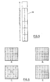
- a display field 80 of only 8 by 8 pixels is shown. Normally the display field will be of the order of 103 by 103 pixels. Likewise, for ease of illustration and explanation, only a small palette 38, of 32 locations is shown. As mentioned above, a palette will normally comprise of the order of 256 locations. However, it will be understood that these values are merely illustrative, and in practice the display field and the number of palette entries may be of any appropriate size.
- the data in the display buffer is updated under control of the windowing logic 68. If this operation means that a change is necessary to the contents of the palette, then the palette and the translation table will be updated as well as explained above. It will be appreciated that the contents of the palette can be changed independently of that of the translation table and the display buffer contents if it is desired, for example to change the colours, only, on the display screen without changing other aspects of the data display severelyed. For example, the foreground and the background of a piece of text could be changed in one go by swapping the colour values stored in two palette locations.
- the windowing logic 68 is responsive to input data specifying the number of tasks which each require a window to be specified for their respective presentation spaces (in this case four tasks) and also responsive to input data specifying the colours used by each of the tasks and the order of priority for the windows to be displayed.
- This input data may be provided in any appropriate way, for example by direct user input.
- the windowing logic initiates a first phase in which the initial data is written into the display buffer by issuing a command over the system bus to cause the DACL to put a valid signal on the line 59 to the OR gate to isolate the range comparator.
- the previous content of the display buffer is not taken into account during this phase as the valid signal output by the OR gate 59 causes the multiplexer 64 to select the data supplied by the windowing logic via the DACL when this is to be written into the display buffer.
- the display screen will normally not be refreshed during this phase.
- the windowing logic issues display buffer addresses to the DACL specifying the outline of the each of the windows to be displayed and the index values to be stored at locations within those windows. It is convenient to supply the index values of a window in the order of scanning of the display for refreshing the display screen. This is not a requirement in the present case as the data in the display buffer can updated in a random access manner. However, it is conventional to update the display buffer in this way. Usually, a display screen is scanned line by line and within each line, pixel by pixel, although any other suitable technique for scanning the display buffer could be used.
- the DACL on receipt of the outline and content data, causes the index values to be stored at the indicated locations.
- This facility can be incorporated as part of the functions of the DACL and may require as input parameters, for example, the top left and bottom right coordinates of a rectangular area to be filled.
- the outline and content data is supplied window by window in ascending order of window priority. In this way, the data for a window of a higher priority can replace the data of a window of lower priority where the pixel positions overlap.
- the whole display field 80 forms the lowest priority window, here window "0", as shown in Figure 4B.
- Window "0" can comprise pixels having four different colours as defined in the palette 38 at locations 0 to 3.
- the initial data to be displayed in the window is the background colour "A" for this window which is specified by the location 0 in the palette.
- the windowing logic issues data identifying the outline of the window "0" (eg. the top left (0,0) and bottom right (7,7) of the rectangular window) followed by a stream of zeros (ie. the index value for the colour "A” for that window).
- the area fill facility of the DACL determines from the outline for the window, the locations into which the zeros are to be written (ie the whole of the display buffer) and writes the zeros into those locations.
- Figure 4A shows the content of the display buffer after this stage.
- Window “1” is the window having the second lowest priority.
- This window can contain pixels having four different colours as defined in the palette 38 at locations 4 to 7.
- the windowing logic issues data identifying the outline of the window "1” (eg. by means of the top left (2,0) and the bottom right (7,4) corners of the rectangular window) followed by a stream of fives (ie. the index value for the colour "B" for that window).
- the DACL determines from the outline for the window, the locations into which the fives are to be written and writes them into those locations. In doing so, certain of the zeros stored for the window "0" are over written.
- Figure 4C shows the content of the display buffer following this stage and Figure 4D represents the layout of the windows.
- Window “2" is the window having the next, higher priority.
- This window can contain pixels having four different colours as defined in the palette 38 at locations 8 to 11.
- the windowing logic issues data identifying the display buffer locations of the top left (2,2) and the bottom right (4,5) corners of the rectangular window "2" followed by a stream of index values representing a given colour for that window (eg. a string of nines, for the colour "H”).
- the DACL determines the extent of the window from the corner values and writes the nines into the appropriate locations in the same way as before. In doing so, the values previously stored at those locations are overwritten.
- Figure 4E shows the content of the display buffer following this stage and Figure 4F represents the layout of the windows.
- Window “3” is the window having the highest priority.
- This window can contain pixels having eight different colours as defined in the palette 38 at locations 12 to 19.
- the DACL determines the extent of the window and writes the eighteens into the appropriate locations in the same way as before. Once again, the values previously stored at these locations are overwritten.
- Figure 4G shows the content of the display buffer following this stage and Figure 4H represents the visible extent of the windows.
- the actual colours which appear on the screen are determined by the content of the palette entries indexed, or addressed, by the index values in the display buffer.
- Figure 4 represents the content of the palette, where the letters A, B, C, D, E, F, G, H, I and J each represent different colours.
- the palette entries are assumed to be divided into five ranges, locations 0 - 3, 4 - 7, 8 - 11, 12 - 19 and 20 - 31, one for each of the four windows and one which is unused at present but may be used for additional windows. It will be noted that some colours are specified in more than one range. This is illustrative of the versatility of the present invention.
- the windowing logic causes the DACL to remove the logical true from the line 59 and replace it with a logical false. This has the effect of enabling the range comparator to control the multiplexer 60.
- the windowing logic is then in a position to put update information for the display buffer onto the personal computer bus when updating the display buffer contents. This involves translating the colour values used by the respective tasks using the translation table 74 and multiplexing the data from the presentation spaces associated with those tasks onto the personal computer bus. Each time the source of the update data changes, the windowing logic sends the maximum and minimum values associated with the range of values for the appropriate presentation space to the display buffer and causes the DACL in the display adapter to store those values in the maximum and minimum registers, 50 and 48, respectively.
- the DACL 42 addresses the display adapter and causes data previously stored in the display buffer at the locations for which the update data is destined to be read out and supplied on the connection 44.
- the DACL also causes the update data to be passed over the path 62 to the multiplexer switch 60 in synchronism with the supply of the data from corresponding display buffer locations over the connection 44.
- Each data value read out of the display buffer 38 is compared to the range defined by the values in the maximum and minimum registers. If the value read out falls within the range, then the range comparator outputs a true value which in turn causes the multiplexer switch to select the data item in its first input D1 for updating the display buffer. In other words, if the value read out falls within the range, then the corresponding item of update information is written into the appropriate location in the display buffer. If the value read out does not fall within the range, then that pixel position lies outside the window in question and accordingly the range comparator outputs a false value which causes the multiplexer switch to select the data value read out of the display buffer (ie. the data item at its second input D2) to be rewritten into the display.
- a screen of data forming a presentation space for the task associated with window "2" contains the information shown in Figure 6A.
- each item of update information By taking each item of update information in turn, examining the content of the location for which that item of update information is destined to see whether the value at that location falls within the appropriate range of values (ie. between 8 and 11), and storing only those values where the comparison is positive, only the update information which corresponds to the visible part of the window of the presentation space (ie. those locations where a "9" is stored in the display buffer in Figure 5G) will be used to update the display buffer to create modified display buffer contents as illustrated at Figure 6B.
- this update process can be repeated indefinitely.
- the screen of data forming a presentation space for the task associated with window "2" is changed to the information shown in Figure 6C.
- the windowing logic supplies the maximum and minimum values for the range (ie. 11 and 8) and these are stored in the maximum and minimum registers 50 and 48 by the DACL.
- a stream of update information is then supplied as before.
- the other windows are updated in the same way. It should be noted that this occurs without any of the tasks being aware that they do not have exclusive use of the display field. In other words, the window management is transparent to the tasks themselves. Apart from the constraints on the number of colours available at any one time to a task window which results from the partitioning of the palette, there are no constraints on the colours which are available to the tasks. In the example shown in the Figures, up to four different colours are available to each of tasks 0, 1 and 2 for display in windows 0, 1 and 2, respectively and up to eight colours are available to task 3 for display in window 3. Each of these colours may be chosen from the 2 n possible ones which may be defined by a palette entry, where n in the number of bits per entry in the palette. Thus, as shown in Figure 5, some colours may be available in a number of different windows.
- Figure 2 shows the update information being supplied directly from the DACL 42 to the multiplexer 60.
- Figure 7 shows a variation on the Figure 2 example in which this data may be modified by performing a desired logical operation on it in combination with the data read out of the corresponding locations in the display buffer.
- an arithmetic and logic unit (ALU) 76 may be provided in the data path 62, whereby a first data input D1 of the ALU 88 is connected to the first part of the data path 62 and the data output DO of the ALU 88 is connected to the second half of the data path 62.
- the second data input D2 of the ALU 88 is connected to the data connection 44 from the display buffer 36.
- a control path 78 is provided from the DACL 42 to the ALU 76 for selecting an operation to be performed.
- the ALU can be of conventional form and allows various logical and arithmetic operations to be performed on the data already displayed on the screen and the update data such as AND, OR, EXCLUSIVE OR, AVERAGE and so on under the control of the DACL and in response to control information from the windowing logic.
- a display system in accordance with the invention allows more efficient window processing.
- the initial setting up of the display buffer ie. the first phase
- the setting up phase only has to be done very infrequently, at system initialisation and when the configuration of the windows in the display field is changed.
- Normal updating of the display buffer ie. in the second phase
- index values stored at individual pixel positions in the display buffer to determine the visible extent of a given window within the display field.
- only one range comparator is shown in Figures 2 and 7. This assumes that only one pixel position is read from the display buffer at one time. It would be possible to include a plurality of range comparators and to read out a plurality of pixel positions from the display buffer at one time for processing in parallel. Although this would involve duplicating some hardware - there would need to be more lines on the feedback connection 44 for example - the display buffer could be updated more quickly.
- a display buffer with only a single output port may be used. The only effect of this is that the amount of time per refresh scan, which is available for update processing will be reduced. Also, although it is assumed in the above, that the display buffer is part of a discrete display adapter, this need not be the case.
- the display buffer could in practice form part of the random access memory of the personal computer and be within the address space of the CPU 10.
- range comparator shown in Figures 2 and 7 is implemented in hardware, it will be appreciated that this could be provided in any appropriate manner, for example by appropriate software. This might be desirable in a low cost embodiment with the display buffer in the random address space of the personal computer.
- the colour code values of respective presentation spaces are translated by the windowing logic, this translation would not be necessary if the tasks were constrained in some other way to use colour code values within the appropriate ranges of values for the corresponding windows. In this case, the translation table would not be needed. A result of this modification might be, however, that the existence of the windowing facility would not be transparent to the tasks.
- the present invention is not limited to an implementation in a personal computer.
- the display system could, for example, be implemented in a terminal for a host processor, or as a subsystem for the host processor.
- the display system could be in the form of an add-on card for an existing computer system (eg. a personal computer).
Landscapes
- Engineering & Computer Science (AREA)
- Physics & Mathematics (AREA)
- Computer Hardware Design (AREA)
- General Physics & Mathematics (AREA)
- Theoretical Computer Science (AREA)
- Controls And Circuits For Display Device (AREA)
- Digital Computer Display Output (AREA)
- Image Generation (AREA)
Applications Claiming Priority (2)
| Application Number | Priority Date | Filing Date | Title |
|---|---|---|---|
| GB8804166A GB2215168A (en) | 1988-02-23 | 1988-02-23 | Windows with restricted colour range have priority defined by colour codes |
| GB8804166 | 1988-02-23 |
Publications (3)
| Publication Number | Publication Date |
|---|---|
| EP0329892A2 true EP0329892A2 (fr) | 1989-08-30 |
| EP0329892A3 EP0329892A3 (en) | 1990-12-27 |
| EP0329892B1 EP0329892B1 (fr) | 1994-08-03 |
Family
ID=10632195
Family Applications (1)
| Application Number | Title | Priority Date | Filing Date |
|---|---|---|---|
| EP88310189A Expired - Lifetime EP0329892B1 (fr) | 1988-02-23 | 1988-10-28 | Système d'affichage comportant un mécanisme pour fenêtres |
Country Status (6)
| Country | Link |
|---|---|
| US (1) | US5091720A (fr) |
| EP (1) | EP0329892B1 (fr) |
| JP (1) | JPH01310432A (fr) |
| CA (1) | CA1328513C (fr) |
| DE (1) | DE3850955T2 (fr) |
| GB (1) | GB2215168A (fr) |
Cited By (2)
| Publication number | Priority date | Publication date | Assignee | Title |
|---|---|---|---|---|
| EP0431754A2 (fr) * | 1989-12-07 | 1991-06-12 | Advanced Micro Devices, Inc. | Circuit de conversion de couleurs |
| EP0448287A2 (fr) * | 1990-03-16 | 1991-09-25 | Hewlett-Packard Company | Méthode et appareil de découpage de pixels de fenêtres source et destination dans un système graphique |
Families Citing this family (37)
| Publication number | Priority date | Publication date | Assignee | Title |
|---|---|---|---|---|
| US5354695A (en) | 1992-04-08 | 1994-10-11 | Leedy Glenn J | Membrane dielectric isolation IC fabrication |
| US5235677A (en) * | 1989-06-02 | 1993-08-10 | Atari Corporation | Raster graphics color palette architecture for multiple display objects |
| JPH03177893A (ja) * | 1989-12-06 | 1991-08-01 | Toshiba Corp | マルチウィンドウ表示装置 |
| JP2622011B2 (ja) * | 1990-04-16 | 1997-06-18 | 三菱電機株式会社 | 画面切替方法 |
| US5347621A (en) * | 1990-09-19 | 1994-09-13 | Sony Corporation | Method and apparatus for processing image data |
| JPH0685144B2 (ja) * | 1990-11-15 | 1994-10-26 | インターナショナル・ビジネス・マシーンズ・コーポレイション | オーバレイ及びアンダレイの選択的制御装置 |
| US5546105A (en) * | 1991-07-19 | 1996-08-13 | Apple Computer, Inc. | Graphic system for displaying images in gray-scale |
| US5592678A (en) * | 1991-07-23 | 1997-01-07 | International Business Machines Corporation | Display adapter supporting priority based functions |
| EP0567971B1 (fr) * | 1992-04-27 | 1999-07-28 | Sony Corporation | Appareil de traitement de l 'information assurant la compatibilité entre different modèles |
| JP2793463B2 (ja) * | 1992-04-28 | 1998-09-03 | インターナショナル・ビジネス・マシーンズ・コーポレイション | カラーセツト選択装置及びその方法並びにカラー選択管理方法 |
| JP2583003B2 (ja) * | 1992-09-11 | 1997-02-19 | インターナショナル・ビジネス・マシーンズ・コーポレイション | グラフィックス表示システムにおけるイメージ表示方法、フレーム・バッファ及びグラフィックス表示システム |
| WO1994009458A1 (fr) * | 1992-10-13 | 1994-04-28 | Gilbarco Inc. | Appareil et procede d'affichage d'informations video |
| US5572235A (en) * | 1992-11-02 | 1996-11-05 | The 3Do Company | Method and apparatus for processing image data |
| US5838389A (en) * | 1992-11-02 | 1998-11-17 | The 3Do Company | Apparatus and method for updating a CLUT during horizontal blanking |
| US5596693A (en) * | 1992-11-02 | 1997-01-21 | The 3Do Company | Method for controlling a spryte rendering processor |
| US5481275A (en) | 1992-11-02 | 1996-01-02 | The 3Do Company | Resolution enhancement for video display using multi-line interpolation |
| US5752073A (en) * | 1993-01-06 | 1998-05-12 | Cagent Technologies, Inc. | Digital signal processor architecture |
| US6091430A (en) * | 1993-03-31 | 2000-07-18 | International Business Machines Corporation | Simultaneous high resolution display within multiple virtual DOS applications in a data processing system |
| US5452406A (en) * | 1993-05-14 | 1995-09-19 | Microsoft Corporation | Method and system for scalable borders that provide an appearance of depth |
| US5485562A (en) * | 1993-09-14 | 1996-01-16 | International Business Machines Corporation | System and method for clipping pixels drawn in one of plurality of windows in a computer graphics system |
| US5515081A (en) * | 1993-11-30 | 1996-05-07 | Borland International, Inc. | System and methods for improved storage and processing of BITMAP images |
| US5838318A (en) * | 1995-11-10 | 1998-11-17 | Intel Corporation | Method and apparatus for automatically and intelligently arranging windows on a display device |
| JPH09281931A (ja) * | 1996-04-10 | 1997-10-31 | Fujitsu Ltd | 表示装置および該表示装置の駆動回路ならびに表示装置の駆動方法 |
| US6551857B2 (en) | 1997-04-04 | 2003-04-22 | Elm Technology Corporation | Three dimensional structure integrated circuits |
| US6108003A (en) * | 1998-03-18 | 2000-08-22 | International Business Machines Corporation | Maintaining visibility and status indication of docked applications and application bars |
| JP2003506742A (ja) * | 1999-08-01 | 2003-02-18 | ディープ ヴィデオ イメージング リミテッド | 層状スクリーンを備えた、相互作用的(インタラクティブ)な3次元ディスプレイ |
| AU769107B2 (en) | 1999-08-19 | 2004-01-15 | Pure Depth Limited | Data display for multiple layered screens |
| US7730413B1 (en) * | 1999-08-19 | 2010-06-01 | Puredepth Limited | Display method for multiple layered screens |
| AU769120B2 (en) * | 1999-08-19 | 2004-01-15 | Pure Depth Limited | Control of depth movement for visual display with layered screens |
| NZ511444A (en) | 2001-05-01 | 2004-01-30 | Deep Video Imaging Ltd | Information display |
| JP3812368B2 (ja) * | 2001-06-06 | 2006-08-23 | 豊田合成株式会社 | Iii族窒化物系化合物半導体素子及びその製造方法 |
| NZ514119A (en) * | 2001-09-11 | 2004-06-25 | Deep Video Imaging Ltd | Improvement to instrumentation |
| US6883045B1 (en) * | 2001-10-15 | 2005-04-19 | Advanced Micro Devices, Inc. | Apparatus for reordering graphics responses in a peripheral interface circuit for an I/O node of a computer system |
| US7402897B2 (en) | 2002-08-08 | 2008-07-22 | Elm Technology Corporation | Vertical system integration |
| NZ521505A (en) * | 2002-09-20 | 2005-05-27 | Deep Video Imaging Ltd | Multi-view display |
| NZ525956A (en) * | 2003-05-16 | 2005-10-28 | Deep Video Imaging Ltd | Display control system for use with multi-layer displays |
| CN102473398B (zh) * | 2009-07-17 | 2015-04-29 | 三菱电机株式会社 | 设备操作显示装置以及空调系统 |
Citations (3)
| Publication number | Priority date | Publication date | Assignee | Title |
|---|---|---|---|---|
| US4509043A (en) * | 1982-04-12 | 1985-04-02 | Tektronix, Inc. | Method and apparatus for displaying images |
| EP0149309A2 (fr) * | 1983-11-03 | 1985-07-24 | Unisys Corporation | Système d'affichage électronique de plusieurs images sur l'écran d'un T.R.C. de façon que certaines images soient plus prononcées que d'autres |
| EP0223557A2 (fr) * | 1985-11-15 | 1987-05-27 | Data General Corporation | Commande d'affichage dans un système de traitement de données |
Family Cites Families (5)
| Publication number | Priority date | Publication date | Assignee | Title |
|---|---|---|---|---|
| US4484187A (en) * | 1982-06-25 | 1984-11-20 | At&T Bell Laboratories | Video overlay system having interactive color addressing |
| EP0121015B1 (fr) * | 1983-03-31 | 1990-03-07 | International Business Machines Corporation | Gestion de l'espace de présentation et visualisation dans une partie déterminée de l'écran d'un appareil terminal virtuel à fonctions multiples |
| JPS61133983A (ja) * | 1984-12-04 | 1986-06-21 | シャープ株式会社 | 画像表示装置 |
| US4794386A (en) * | 1986-04-11 | 1988-12-27 | Profit Technology, Inc. | Data integrator for video display including windows |
| US4876533A (en) * | 1986-10-06 | 1989-10-24 | Schlumberger Technology Corporation | Method and apparatus for removing an image from a window of a display |
-
1988
- 1988-02-23 GB GB8804166A patent/GB2215168A/en not_active Withdrawn
- 1988-10-28 EP EP88310189A patent/EP0329892B1/fr not_active Expired - Lifetime
- 1988-10-28 DE DE3850955T patent/DE3850955T2/de not_active Expired - Fee Related
-
1989
- 1989-01-17 CA CA000588444A patent/CA1328513C/fr not_active Expired - Fee Related
- 1989-01-20 JP JP1010108A patent/JPH01310432A/ja active Granted
- 1989-01-30 US US07/304,382 patent/US5091720A/en not_active Expired - Fee Related
Patent Citations (3)
| Publication number | Priority date | Publication date | Assignee | Title |
|---|---|---|---|---|
| US4509043A (en) * | 1982-04-12 | 1985-04-02 | Tektronix, Inc. | Method and apparatus for displaying images |
| EP0149309A2 (fr) * | 1983-11-03 | 1985-07-24 | Unisys Corporation | Système d'affichage électronique de plusieurs images sur l'écran d'un T.R.C. de façon que certaines images soient plus prononcées que d'autres |
| EP0223557A2 (fr) * | 1985-11-15 | 1987-05-27 | Data General Corporation | Commande d'affichage dans un système de traitement de données |
Cited By (4)
| Publication number | Priority date | Publication date | Assignee | Title |
|---|---|---|---|---|
| EP0431754A2 (fr) * | 1989-12-07 | 1991-06-12 | Advanced Micro Devices, Inc. | Circuit de conversion de couleurs |
| EP0431754A3 (en) * | 1989-12-07 | 1991-08-14 | Advanced Micro Devices, Inc. | Color translation circuit |
| EP0448287A2 (fr) * | 1990-03-16 | 1991-09-25 | Hewlett-Packard Company | Méthode et appareil de découpage de pixels de fenêtres source et destination dans un système graphique |
| EP0448287A3 (en) * | 1990-03-16 | 1993-04-21 | Hewlett-Packard Company | Method and apparatus for pixel clipping source and destination windows in a graphics system |
Also Published As
| Publication number | Publication date |
|---|---|
| DE3850955D1 (de) | 1994-09-08 |
| GB8804166D0 (en) | 1988-03-23 |
| JPH0532769B2 (fr) | 1993-05-17 |
| EP0329892A3 (en) | 1990-12-27 |
| GB2215168A (en) | 1989-09-13 |
| US5091720A (en) | 1992-02-25 |
| DE3850955T2 (de) | 1995-03-16 |
| JPH01310432A (ja) | 1989-12-14 |
| EP0329892B1 (fr) | 1994-08-03 |
| CA1328513C (fr) | 1994-04-12 |
Similar Documents
| Publication | Publication Date | Title |
|---|---|---|
| EP0329892B1 (fr) | Système d'affichage comportant un mécanisme pour fenêtres | |
| EP0279226B1 (fr) | Interface pour l'affichage vidéo graphique à haute résolution | |
| US5208908A (en) | Display system having a font cache for the temporary storage of font data | |
| EP0279229B1 (fr) | Système de visualisation graphique | |
| US4916301A (en) | Graphics function controller for a high performance video display system | |
| US5241656A (en) | Depth buffer clipping for window management | |
| US5430841A (en) | Context management in a graphics system | |
| US4566005A (en) | Data management for plasma display | |
| US5193148A (en) | Method and apparatus for pixel clipping source and destination windows in a graphics system | |
| EP0279230A2 (fr) | Interface vidéo avec branchement des données | |
| EP0279225B1 (fr) | Compteurs à configuration variable pour l'adressage dans les systèmes de visualisation graphiques | |
| EP0284904B1 (fr) | Système de visualisation pour une mémoire de police de symboles | |
| EP0279227A2 (fr) | Générateur de tracé de vecteur pour l'affichage vidéo à balayage par trame | |
| EP0661681A1 (fr) | Adaptateur d'affichage | |
| EP0147542B1 (fr) | Système d'affichage à fenêtres multiples | |
| JPH08249502A (ja) | 補助バッファ情報を用いる改良型グラフィクス・ピッキング方法及び装置 | |
| EP0381892B1 (fr) | Systèmes d'affichage pour ordinateur comportant des fenêtres | |
| US4562450A (en) | Data management for plasma display | |
| CA1229439A (fr) | Systeme d'affichage de donnees | |
| US6337690B1 (en) | Technique for reducing the frequency of frame buffer clearing | |
| EP0121070A2 (fr) | Système de gestion de panneaux d'affichage à plasma | |
| EP0422294A1 (fr) | Système d'affichage | |
| EP0279231B1 (fr) | Processeur d'affichage vidéo en mode graphique pour un système d'affichage vidéo à haute performance | |
| GB2224622A (en) | Apparatus for extending windows using Z buffer memory | |
| JPH07199907A (ja) | 表示制御装置 |
Legal Events
| Date | Code | Title | Description |
|---|---|---|---|
| PUAI | Public reference made under article 153(3) epc to a published international application that has entered the european phase |
Free format text: ORIGINAL CODE: 0009012 |
|
| AK | Designated contracting states |
Kind code of ref document: A2 Designated state(s): DE FR GB |
|
| 17P | Request for examination filed |
Effective date: 19891214 |
|
| PUAL | Search report despatched |
Free format text: ORIGINAL CODE: 0009013 |
|
| AK | Designated contracting states |
Kind code of ref document: A3 Designated state(s): DE FR GB |
|
| 17Q | First examination report despatched |
Effective date: 19930614 |
|
| GRAA | (expected) grant |
Free format text: ORIGINAL CODE: 0009210 |
|
| AK | Designated contracting states |
Kind code of ref document: B1 Designated state(s): DE FR GB |
|
| REF | Corresponds to: |
Ref document number: 3850955 Country of ref document: DE Date of ref document: 19940908 |
|
| ET | Fr: translation filed | ||
| PLBE | No opposition filed within time limit |
Free format text: ORIGINAL CODE: 0009261 |
|
| STAA | Information on the status of an ep patent application or granted ep patent |
Free format text: STATUS: NO OPPOSITION FILED WITHIN TIME LIMIT |
|
| 26N | No opposition filed | ||
| PGFP | Annual fee paid to national office [announced via postgrant information from national office to epo] |
Ref country code: GB Payment date: 19981001 Year of fee payment: 11 |
|
| PGFP | Annual fee paid to national office [announced via postgrant information from national office to epo] |
Ref country code: FR Payment date: 19981012 Year of fee payment: 11 |
|
| PGFP | Annual fee paid to national office [announced via postgrant information from national office to epo] |
Ref country code: DE Payment date: 19981019 Year of fee payment: 11 |
|
| PG25 | Lapsed in a contracting state [announced via postgrant information from national office to epo] |
Ref country code: GB Free format text: LAPSE BECAUSE OF NON-PAYMENT OF DUE FEES Effective date: 19991028 |
|
| GBPC | Gb: european patent ceased through non-payment of renewal fee |
Effective date: 19991028 |
|
| PG25 | Lapsed in a contracting state [announced via postgrant information from national office to epo] |
Ref country code: FR Free format text: LAPSE BECAUSE OF NON-PAYMENT OF DUE FEES Effective date: 20000630 |
|
| PG25 | Lapsed in a contracting state [announced via postgrant information from national office to epo] |
Ref country code: DE Free format text: LAPSE BECAUSE OF NON-PAYMENT OF DUE FEES Effective date: 20000801 |
|
| REG | Reference to a national code |
Ref country code: FR Ref legal event code: ST |