EP0326327B1 - Apparatus for superimposing graphic title image signals onto a video signal - Google Patents
Apparatus for superimposing graphic title image signals onto a video signal Download PDFInfo
- Publication number
- EP0326327B1 EP0326327B1 EP89300655A EP89300655A EP0326327B1 EP 0326327 B1 EP0326327 B1 EP 0326327B1 EP 89300655 A EP89300655 A EP 89300655A EP 89300655 A EP89300655 A EP 89300655A EP 0326327 B1 EP0326327 B1 EP 0326327B1
- Authority
- EP
- European Patent Office
- Prior art keywords
- horizontal
- vertical
- address
- graphic
- signals
- Prior art date
- Legal status (The legal status is an assumption and is not a legal conclusion. Google has not performed a legal analysis and makes no representation as to the accuracy of the status listed.)
- Expired - Lifetime
Links
- 230000004044 response Effects 0.000 claims description 11
- 230000001360 synchronised effect Effects 0.000 claims description 5
- 230000003068 static effect Effects 0.000 claims description 2
- 230000000694 effects Effects 0.000 description 13
- 230000006870 function Effects 0.000 description 9
- 239000000463 material Substances 0.000 description 6
- 239000002131 composite material Substances 0.000 description 5
- 230000008859 change Effects 0.000 description 4
- 238000003384 imaging method Methods 0.000 description 4
- 238000000034 method Methods 0.000 description 4
- WHXSMMKQMYFTQS-UHFFFAOYSA-N Lithium Chemical compound [Li] WHXSMMKQMYFTQS-UHFFFAOYSA-N 0.000 description 3
- 238000010586 diagram Methods 0.000 description 3
- 229910052744 lithium Inorganic materials 0.000 description 3
- 238000006243 chemical reaction Methods 0.000 description 2
- 238000003780 insertion Methods 0.000 description 2
- 230000037431 insertion Effects 0.000 description 2
- 230000008569 process Effects 0.000 description 2
- 230000003750 conditioning effect Effects 0.000 description 1
- 230000006378 damage Effects 0.000 description 1
- 238000013500 data storage Methods 0.000 description 1
- 238000001514 detection method Methods 0.000 description 1
- 230000000977 initiatory effect Effects 0.000 description 1
- 230000010354 integration Effects 0.000 description 1
- 230000007774 longterm Effects 0.000 description 1
- 239000011159 matrix material Substances 0.000 description 1
- 230000003287 optical effect Effects 0.000 description 1
- 230000002093 peripheral effect Effects 0.000 description 1
- 230000009467 reduction Effects 0.000 description 1
Images


Classifications
-
- H—ELECTRICITY
- H04—ELECTRIC COMMUNICATION TECHNIQUE
- H04N—PICTORIAL COMMUNICATION, e.g. TELEVISION
- H04N5/00—Details of television systems
- H04N5/222—Studio circuitry; Studio devices; Studio equipment
- H04N5/262—Studio circuits, e.g. for mixing, switching-over, change of character of image, other special effects ; Cameras specially adapted for the electronic generation of special effects
- H04N5/265—Mixing
-
- H—ELECTRICITY
- H04—ELECTRIC COMMUNICATION TECHNIQUE
- H04N—PICTORIAL COMMUNICATION, e.g. TELEVISION
- H04N5/00—Details of television systems
- H04N5/222—Studio circuitry; Studio devices; Studio equipment
- H04N5/262—Studio circuits, e.g. for mixing, switching-over, change of character of image, other special effects ; Cameras specially adapted for the electronic generation of special effects
- H04N5/278—Subtitling
-
- H—ELECTRICITY
- H03—ELECTRONIC CIRCUITRY
- H03K—PULSE TECHNIQUE
- H03K21/00—Details of pulse counters or frequency dividers
- H03K21/38—Starting, stopping or resetting the counter
-
- H—ELECTRICITY
- H04—ELECTRIC COMMUNICATION TECHNIQUE
- H04N—PICTORIAL COMMUNICATION, e.g. TELEVISION
- H04N5/00—Details of television systems
- H04N5/04—Synchronising
-
- H—ELECTRICITY
- H04—ELECTRIC COMMUNICATION TECHNIQUE
- H04N—PICTORIAL COMMUNICATION, e.g. TELEVISION
- H04N5/00—Details of television systems
- H04N5/76—Television signal recording
- H04N5/765—Interface circuits between an apparatus for recording and another apparatus
- H04N5/77—Interface circuits between an apparatus for recording and another apparatus between a recording apparatus and a television camera
-
- H—ELECTRICITY
- H04—ELECTRIC COMMUNICATION TECHNIQUE
- H04N—PICTORIAL COMMUNICATION, e.g. TELEVISION
- H04N9/00—Details of colour television systems
- H04N9/77—Circuits for processing the brightness signal and the chrominance signal relative to each other, e.g. adjusting the phase of the brightness signal relative to the colour signal, correcting differential gain or differential phase
Definitions
- This invention relates to an apparatus for superimposing graphic (for example, title) image signals onto a video signal, and for causing such superimposed images to scroll across the video picture derived from the video signal.
- Embodiments of the invention find application in so-called video titlers and telopers (or opaque projectors), and particularly in video cameras of the type having an image pick-up device and a video tape recorder (VTR) within the same housing.
- VTR video tape recorder
- Apparatus for superimposing graphic title images onto video signals have been developed as peripheral equipment for use with VTRs.
- graphic title images referred to generally as graphics
- graphics are used in video dubbing to superimpose, or insert, graphic data onto a recorded video signal.
- a composite video signal containing graphic information is recorded.
- character generators which are capable of generating various types of alphanumeric patterns.
- the patterns formed by such character generators appear as title image signals, and are superimposed onto video signals that are reproduced from the VTR or that may be derived from an image pick-up device.
- Such character generators are usually not suited for integration with presently available video cameras.
- a video camera is usually a hand-held device containing a VTR and an image pick-up section within the same housing. Character generators usually are too large, too heavy and too expensive to be integrated into such video cameras.
- the graphic insertion proposal of the type just described writes graphic data into the memory on a line-by-line basis, with each line generally being divided into several image units, analogous to pixels.
- the location of the graphic data that are read from the memory, relative to a picture image plane is, of course, substantially identical to the location of those graphic data when they were written into the memory.
- graphic material occupied the centre portion of the image plane when it was written into the memory
- the graphics read from the memory and superimposed onto an input video signal likewise will occupy the centre portion of the image plane.
- original graphics data disposed at the bottom or top of the image plane when written into the memory will occupy the bottom or top of that same image plane when read.
- graphics data located to the left or right of the image plane when written will be superimposed to the left or right of the image plane when read.
- the particular position of the graphic data that are imaged by the pick-up section remains fixed when those graphic data are subsequently superimposed onto another video signal imaged by the pick-up section.
- the user of the video camera is provided with limited flexibility in adjusting the position of the graphic data after those data have been imaged and stored in the memory. Accordingly, a drawback of such graphic insertion apparatus is that the graphic data that are stored in the memory cannot subsequently be scrolled horizontally or vertically, relative to a video picture, or video image plane.
- Patent Abstracts of Japan, Vol. 10, no. 24 discloses a video camera device comprising addressable storage means, address generating means, address control means and superimposing means interacting such as to superimpose a graphic image on a video image. That disclosure and the disclosure in European patent specification EP-A2-0 131 454 teach how characters can be scrolled.
- EP-A-0 139 095 discloses an apparatus for displaying graphic data obtained from stored graphic data, the graphic data being stored in storage means and the apparatus comprising address control means establishing an effective image range (corresponding to a "physical screen") corresponding to the effective picture area of a video picture (raster scan display) derived from the graphic data, and shift means for changing the addresses (by changing the starting read address of the graphic data memory and following ("linear") addresses in the address range defining the "physical screen") represented by the address signals generated by address generating means by a predetermined number of addresses (pel or character positions) for every display, output means being responsive to the generated changed addresses and the "physical screen” range of addresses to supply to image generating means the read out graphic image data from the graphic data storage means at intervals within the effective image range ("physical screen") and determined by the changed address signals, in order to generate a video picture representing a graphic image that scrolls (horizontally or/and vertically) across the display or effective image range.
- address control means establishing an effective image range (corresponding to a "
- an apparatus for superimposing graphic image signals onto a video signal comprising: addressable storage means for storing graphic image data representing respective elements of respective horizontal lines of a graphic image; a source of horizontal and vertical synchronizing signals synchronized with such signals of said video signal; a source of clock pulses of a frequency which divides a horizontal line interval into multiple discrete zones; horizontal and vertical address counting means for generating timed address signals to read out said image data from said addressable storage means; means for supplying said clock pulses to said horizontal address counting means for counting thereby, whereby said count of said horizontal address counting means represents a horizontal address; means for supplying said horizontal synchronizing signals to said vertical address counting means for counting thereby, whereby said count of said vertical address counting means represents a vertical address; horizontal and vertical absolute position counters for counting said clock pulses and said horizontal synchronizing signals respectively; means for resetting said horizontal and vertical absolute position counters in response to said horizontal and vertical synchronizing signals respectively; horizontal and vertical counter control means coupled to said horizontal and vertical
- the apparatus for superimposing graphic title image signals onto an input video signal.
- Graphic title image data are stored in an addressable store and are read out therefrom in response to address signals generated by an address generator.
- the data read from the store are used to generate graphic title image signals which are superimposed onto the input video signal.
- An address control is coupled to the address generator for establishing an effective image range of addresses to define an effective picture area (or image range) of a video picture derived from the graphic title image data.
- the sequence of the address signals relative to the effective range of addresses is selectively changed by a predetermined number of addresses for every m repetition periods (m is an integer and a repetition period is either a vertical field or a vertical frame) by an address shifter.
- the graphic title image data read from the store at intervals within the effective image range determined by the changed address signals are gated for superposition onto the input video signals and, as a result, the video picture derived from the graphic title image data represents a shifting graphic title image.
- graphic title image data generated by an image pick-up device are written into an addressable memory under the control of horizontal and vertical address generators. Addresses representing discrete locations in successive horizontal lines are limited to those addresses which define an effective image plane, that is, an effective picture area. Subsequently, the same horizontal and vertical address generators are used to read out the graphic title image data from the stored locations within the memory.
- An output circuit which functions as a gate, is enabled (or opened) at times corresponding to the effective image plane, thereby gating the read-out graphic title image data to circuitry which functions to superimpose the read-out data onto an input video signal.
- switches are selectively operated by a user to produce a horizontal and/or vertical scroll effect to the read out graphic title image data.
- This is achieved by changing the horizontal addresses generated by the horizontal address generator by a predetermined amount during each horizontal line interval to effect a horizontal scroll; and by changing the vertical addresses generated by the vertical address generator by another predetermined amount during every m field or frame intervals (m is an integer) to effect a vertical scroll of the graphic title image data.
- m is an integer
- the vertical address generator may be preset to a count of two. This, of course, means that the graphic title image data that may have been stored at addresses 0 and 1 in the memory are not read or, alternatively, if read are not gated out for superposition. Then, m frames later, at line 20 of the normal video frame, the vertical address generator may be preset to a count of four. Now, the graphic title image data stored at vertical addresses 0, 1, 2 and 3 are not gated out for superposition. As this process continues, the graphic title image data superposed onto the video signal and eventually displayed appear to scroll vertically.
- stored graphic title image data may be read out in time-shifted relationship to a field or frame interval, thereby shifting the position of the superposed graphic title image data on the video signal which, in turn, shifts the position at which the graphic title image data are displayed on the video picture.
- shifting the addresses periodically such as by a predetermined amount every m fields or frames, the displayed graphic title image information appears to scroll horizontally or vertically across the video picture.
- the graphic title image data are modulated with colour signal (R, G, B) to produce, for example, red, green or blue graphic title image data; and the colour graphic data are converted to luminance and colour difference signals for superposition onto the input video signal (which, preferably, is itself a composite colour video signal).
- FIG. 1 is a perspective view of a video camera 30 which includes a VTR section for recording video signals in the 8mm format.
- the video camera 30 includes an imaging lens 35 and a photosensitive target, described in greater detail below, on which a scene imaged by the lens 35 is projected.
- the photosensitive device described herein as a charge coupled device (CCD) is a standard image sensor used in video cameras to generate video signals.
- the video signals derived from the CCD and corresponding to the scene which is imaged by the lens 35 is displayed as a television picture in an electronic viewfinder 40.
- CCD charge coupled device
- the video camera 30 also includes a series of switches 31 to 34 that are manually operable, and used for superimposing graphic title image signals onto the video signal generated by the CCD as a scene is imaged.
- the switch 31 when actuated, stores graphic title image data in a memory included within the video camera 30.
- graphic title image data are produced by using the video camera 30 to image graphic information provided on a poster, placard or the like.
- Figure 1 illustrates a placard 100 having graphic information 101 thereon which is picked up by the video camera 30.
- a schematic representation of the graphic information 101 is depicted in Figure 4.
- digital representations of the video signals generated by imaging the placard 100 are written into the aforementioned memory when the switch 31 is actuated.
- the switch 32 when actuated, reads out the graphic title image data stored in the aforementioned memory and supplies those data to circuitry for conversion into video signals compatible with the video signals produced by the CCD when the video camera 30 is used to image a scene. These graphic video signals are superimposed onto the video signals which then are being picked up by the video camera 30.
- Switches 33h and 33v when actuated, effect horizontal and vertical scrolling, respectively, of the graphic video signals relative to the input video signal then being picked up by the video camera 30.
- the graphic title image signals scroll horizontally such that a video picture that may be derived from the graphic title image signals appears to move horizontally across the picture area.
- the actuation of the switch 33v effects a vertical scrolling of the graphic title image signals relative to the video signals picked up by the video camera 30.
- a video picture derived from the graphic title image signals appears to scroll in the vertical direction. The manner in which this horizontal and vertical scrolling is achieved is described below.
- the switch 34 when actuated, selects a particular colour representation for the graphic title image.
- the switch 34 may select red, green or blue (R, G, B) colour signals to modulate the graphic title image data read from the memory, thereby presenting the graphic data as red, green or blue image data.
- R, G, B red, green or blue
- successive actuations of the switch 34 serve to cycle the selected R, G B signal for modulating the graphic title image data.
- the switch 34 may be actuated to select composite R, G, B signals to modulate the graphic title image data, thereby resulting in a white graphic display. It is contemplated that combinations of RGB signals may be selected.
- colour modulation is carried out only when the graphic title image data are read from the memory and supplied to the superposition circuitry, to be described.
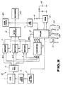
- an image pick-up section 10 comprises a CCD 1, a synchronizing signal generator 2, a CCD drive circuit 3 and an image processing circuit 4.
- Figure 2 also illustrated a VTR 20 and the electronic viewfinder 40.
- the CCD 1 is a photosensitive image pick-up device which, typically, is driven (or scanned) by the CCD drive circuit 3 under the control of horizontal and vertical synchronizing signals generated by the synchronizing signal generator 2.
- signals are derived from the CCD 1 representative of an optical image projected thereon.
- the image signals are processed by the image processing circuit 4 to produce luminance and colour difference video signals.
- the luminance signal Y and the colour difference signals (R-Y) and (B-Y) are supplied to an NTSC encoder 8 by way of superimposing circuits 5, 6 and 7, respectively, for the purpose of generating an NTSC encoded composite video signal.
- the NTSC-encoded video signal is supplied to the VTR 20, whereat it is recorded, and to the viewfinder 40, whereat a video picture corresponding to the NTSC-encoded video signal is displayed.
- the elements 1 to 4, the encoder 8, the VTR 20 and the viewfinder 40 are of known form.
- the superimposing circuits 5, 6 and 7 superimpose onto the video signals supplied thereto by the image processing circuit 4, graphic title image signals derived from what is referred to herein as titler apparatus 12.
- the titler apparatus 12 includes a blanking signal output BLK together with R, G, B signal outputs, the latter being coupled to a converting circuit 15 which converts R, G, B signals to luminance and colour difference signals compatible with the luminance and colour difference signals produced by the image processing circuit 4.
- the luminance signals Y from the image processing circuit 4 and from the converting circuit 15 are coupled to the superimposing circuit 5.
- the red colour difference signals (R-Y) are supplied to the superimposing circuit 6 by the image processing circuit 4 and by the converting circuit 15.
- the blue colour difference signals (B-Y) are coupled by the image processing circuit 4 and the converting circuit 15 to the superimposing circuit 7.
- the superimposing circuits 5 to 7 may be thought of as switching circuits which normally pass the video signal components supplied thereto from the image processing circuit 4. However, in the presence of a blanking signal BLK from the titler apparatus 12, the superimposing circuits 5 to 7 pass the video signal components then being supplied by the converting circuit 15. Hence, portions of the video signal derived from the CCD 1 are replaced by graphic title image signals then being provided by the titler apparatus 12.
- the titler apparatus 12 is coupled to the switches 31 to 34, which are explained in further detail below, for the purpose of controlling write and read operations, horizontal and vertical scroll operations, and colour selection of the graphic title image data.
- the titler apparatus 12 is coupled to an analogue-to-digital (A/D) converter 11 which, in turn, is coupled to the output of the NTSC encoder 8.
- the A/D converter 11 quantizes the video signal produced by the NTSC encoder 8, and particularly the luminance component therein, when the video camera 30 is used to image graphic information provided on the placard 100. In one embodiment, when the level of the luminance signal Y exceeds a predetermined threshold level, the A/D converter 11 supplies a binary "0" to the titler apparatus 12.
- the A/D converter 11 supplies a binary "1" to the titler apparatus. If graphic information 101 ( Figure 4) is provided on a white background, a "1" produced the A/D converter 11 represents the presence of such graphic material.
- A/D converter 11 is described herein as a one-bit converter, it will be appreciated that it may be formed as a multi-bit converter.
- the titler apparatus 12 also is coupled to a memory 13 which, in the preferred embodiment, is formed as a static random access memory (RAM). Graphic title image data produced by the titler apparatus 12 in response to the A/D converter 11 thus may be stored in the memory 13 for prolonged periods of time.
- a back-up power supply having a lithium cell 14, or other long-term, low power drain battery is coupled to the memory 13.
- the voltage produced by the lithium cell 14 is monitored by a voltage reduction detection circuit to provide a suitable alarm when the power level of the lithium cell 14 is reduced to some predetermined limit, and before the graphic title image data stored in the memory 13 are lost.
- the placard 100 having the graphic information 101 thereon is imaged by the video camera 30.
- An image of this graphic material preferably written on a white background, is projected onto the CCD 1; and luminance and colour difference signals representing that image are produced by the image processing circuit 4.
- the luminance and colour difference signal are encoded as an NTSC video signal by the NTSC encoder 8; and the A/D converter 11 converts this analogue video signal to a succession of "1" and "0" bits in a line-by-line manner.
- each line of digital information produced by the A/D converter 11 is stored at corresponding locations in the memory 13.
- the memory 13 may be provided with a number of rows, each row representing a line interval, with each row containing k storage locations.
- the memory 13 may be provided with a number of rows equal to the number of line intervals included in a video picture, with each storage location in a row being formed as an 8-bit store.
- the graphic title image data produced by the A/D converter 11 is stored in the memory 13 on a row-by-row basis, with each row corresponding to a horizontal line interval.
- the user of the video camera 30 now may operate it to image any desired scene.
- the imaged scene is projected on the CCD 1; and the image processing circuit 4 converts the projected image to luminance and colour difference signals.
- These signals are encoded by the NTSC encoder 8 and displayed in the viewfinder 40. If the user wishes, such video signals also may be recorded by the VTR 20.
- the switch 32 is actuated to read out from the memory 13 the stored graphic title image data.
- These graphic title image data are read out in synchronism with the usual horizontal and vertical synchronizing signals and, thus, are synchronized with the video signals being produced by the image processing circuit 4.
- the read out graphic title image data are modulated to produce an RGB signal, and the converting circuit 15 converts the RGB signal to luminance and colour difference signals corresponding thereto.
- These luminance and colour difference video signals representing the graphic title image are supplied to the superimposing circuits 5, 6 and 7 which replace portions of the input video signals supplied by the image processing circuit 4 with portions of the graphic title image signals that occupy the same position in the overall video picture.
- graphic title image signals are superimposed onto the input video signal, and the superimposed signals are displayed in the viewfinder 40.
- Such graphic information superimposed onto the scene picked up by the video camera 30 may be recorded in the VTR 20.
- the superimposed graphic title image signals are scrolled horizontally or vertically, respectively, relative to the video signal upon which they are superimposed. Such horizontal and vertical movement appears in the video picture displayed by the viewfinder 40 and recorded by the VTR 20.
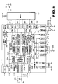
- the titler apparatus 12 includes horizontal and vertical absolute position counters 52h and 52v, horizontal and vertical counter control circuits 53h and 53v, horizontal and vertical address counters 55h and 55v, horizontal and vertical image range defining circuits 54h and 54v, a scroll control circuit 56, a shift register 50 and a gate circuit 51.
- the shift register 50 is coupled to a video input terminal 61 and receives the quantized video signal produced by the A/D converter 11 ( Figure 2).
- the shift register 50 converts the serial bits received from the A/D converter 11 to parallel form; and a parallel output of the shift register 50 is coupled to a data output port 81 connected to the memory 13.
- the shift register 50 also includes a serial output coupled to the gate circuit 51, the latter having enable inputs coupled to the horizontal and vertical image range defining circuits 54h and 54v.
- the gate circuit 51 upon receiving enable signals from both the image range defining circuits 54h and 54v, to pass serial bits supplied from the shift register 50 to output terminals 71, 72 and 73, to be described, and to a superimpose control signal generator 57 by way of selectively operated switches 77, 78 and 79.
- the horizontal absolute position counter 52h is formed as a resettable counter having a clock input coupled to a clock terminal 63, and a reset input coupled to a horizontal synchronizing signal input terminal 64h.
- a suitable source of clock pulses (not shown) is coupled to the clock terminal 63 to supply clock pulses of a frequency which divides a horizontal line interval into multiple discrete zones, analogous to multiple pixels.
- the horizontal synchronizing signal input terminal 64h is coupled to the synchronizing signal generator 2 ( Figure 2) to receive the horizontal synchronizing signals generated thereby.
- the horizontal absolute position counter 52h is reset at the beginning of each horizontal line interval and is then incremented by the clock pulses supplied thereto throughout that line interval.
- the count of the horizontal absolute position counter 52h represents a position along the horizontal line interval, and the output is coupled to the horizontal counter control circuit 53h, and also to the horizontal image range defining circuit 54h, as will be described.
- the vertical absolute position counter 52v includes a clock input coupled to the horizontal synchronizing signal input terminal 64h, and a reset input coupled to a vertical synchronizing signal input terminal 64v.
- the vertical absolute position counter 52v is reset in response to each vertical synchronizing signal supplied to the vertical synchronizing input terminal 64v which is coupled to the synchronizing signal generator 2 ( Figure 2) to receive the vertical synchronizing signals generated thereby.
- the vertical absolute position counter 52v counts horizontal synchronizing signals; and it is seen that the count thereof represents a vertical position (or line number) in a video field interval.
- the count produced by the vertical absolute position counter 52v is coupled to the vertical counter control circuit 53v and to the vertical image range defining circuit 54v, as will be explained below.
- the horizontal address counter 55h produces a count defining the effective horizontal image range of a video picture. It is appreciated that the effective horizontal image range is less than the interval between adjacent horizontal synchronizing signals. Whereas the horizontal absolute position counter 52h provides a count representing a position at any point between horizontal synchronizing signals, the horizontal address counter 55h provides a count representing a point within the left-right borders of the picture area.
- the horizontal address counter 55h includes a clock terminal coupled to the clock terminal 63 and a control input coupled to the horizontal counter control circuit 53h. The count produced by the horizontal address counter 55h functions as an address, and is coupled to a horizontal address port 82 for adding horizontal storage locations in the memory 13. This address count is also supplied to the horizontal image range defining circuit 54h, and is used to produce the horizontal enabling signal supplied to the gate circuit 51.
- the vertical address counter 55v is similar to the horizontal address counter 55h in that it counts horizontal synchronizing signals supplied to the horizontal synchronizing signal input terminal 64h to provide a count within the effective vertical image range. That is, the count of the vertical address counter 55v is within the top and bottom borders of a video picture area.
- a control input of the vertical address counter 55v is coupled to the vertical counter control circuit 53v.
- the count produced by the vertical address counter 55v is coupled to a vertical address port 83 and is used to address vertical storage locations of the memory 13. This vertical address count is also supplied to the vertical image range defining circuit 54v, and is used to produce the vertical enabling signal supplied to the gate circuit 51.
- the horizontal counter control circuit 53h presets the horizontal address counter 55h to a predetermined count when the count attained by the horizontal absolute position counter 52h reaches a previously determined amount.
- the horizontal counter control circuit 53h thus includes an input coupled to the output of the horizontal absolute position counter 52h.
- the horizontal counter control circuit 53h counts the vertical synchronizing signal to detect a count m, as will be described. Accordingly, a suitable input of the horizontal counter control circuit 53h is coupled to the vertical synchronizing signal input terminal 64v.
- the horizontal counter control circuit 53h includes a control input coupled to the scroll control circuit 56 for modifying the particular horizontal absolute position count which is detected by the horizontal counter control circuit 53h for presetting the horizontal address counter 55h, or for changing the preset count.
- the period during which the horizontal address counter 55h lies within the effective horizontal image range also varies, thereby varying the duration that the gate circuit 51 remains open. This, in turn, provides a horizontal scrolling effect to the graphic title image data read from the memory 13 and passed by the gate circuit 51.
- the vertical counter control circuit 53v is similar to the horizontal counter control circuit 53h, and presets the vertical address counter 55v when the position count reached by the vertical absolute position counter 52v reaches a previously determined count. Accordingly, a control output of the vertical counter control circuit 53v is coupled to a preset input of the vertical address counter 55v. The vertical counter control circuit 53v counts vertical synchronizing signals and, therefore, an input is coupled to the vertical synchronizing signal input terminal 64v. Finally, a control input of the vertical counter control circuit 53v is coupled to the scroll control circuit 56 for receiving a scroll control signal therefrom.
- the vertical counter control circuit 53v responds to this scroll control signal to vary the vertical absolute position count that is detected for presetting the vertical address counter 55v or, alternatively, to vary the count to which the vertical address counter 55v is preset. As a result, the period during which the vertical address count remains within an address range defining the vertical image dimension changes; and this produces a vertical scrolling effect to the graphic title image data read from the memory 13 and passed by the gate circuit 51.
- the scroll control circuit 56 is coupled to a horizontal scroll input terminal 90h which is supplied with a reference signal, such as earth potential, when the switch 33h is closed. In response to the closure of the switch 33h, the scroll control circuit 56 supplies a horizontal scroll control signal to the horizontal counter control circuit 53h. As mentioned about, this initiates and enables a horizontal scroll operation.
- the scroll control circuit 56 is also coupled to a vertical scroll input terminal 90v which is supplied with a reference signal when the switch 33v is closed.
- the scroll control circuit 56 responds to this signal to supply a vertical scroll control signal to the vertical counter control circuit 53v, thereby initiating and enabling a vertical scroll operation.
- the scroll control circuit 56 is also coupled to the horizontal and vertical image range defining circuits 54h and 54v to control the gate enabling signals produced thereby. It will be appreciated that these enabling signals define the horizontal and vertical range within the effective image plane, or picture area, over which graphic title image data are read from the memory 13 and gated by the gate circuit 51.
- the switch 34 is arranged, when closed, to provide a control signal to a red control input terminal 74, a green control input terminal 75 or a blue control input terminal 76.
- a control signal is supplied to the terminal 74.
- the control signal is shifted from the terminal 74 to the terminal 75.
- the control signal cycles from one of the red, green and blue control input terminals to the next as the switch 34 is actuated.
- the red control input terminal 74 is coupled to the switch 77 and, in similar manner, the green control input terminal 75 is coupled to the switch 78 and the blue control input terminal 76 is coupled to the switch 79.
- One of the switches 77, 78 and 79 is closed, depending upon which of the red, green and blue control input terminals is provided with a control signal. It is seen that the switches 77, 78 and 79 are connected in common to the output of the gate circuit 51, and each is coupled to a respective one of the red output terminal 71, the green output terminal 72 and the blue output terminal 73.
- Each is also coupled to the superimpose control signal generator 57 which, as an example, functions as an OR circuit to produce a blanking signal BLK coupled to an output terminal 70.
- the red, green and blue output terminals 71, 72 and 73 are coupled to colour signal modulators (not shown) for modulating the serial bits gated from the shift register 50 with R, G and B colour signals.
- the combination of the switches 77 and 79 and the output terminals 71 to 73, together with the colour signal modulator circuits connected to the output terminals 71 to 73, function to convert the bits gated from the shift register 50 to R, G, B colour signals.
- these R, G, B colour signals are supplied to the converting circuit 15 for conversion into luminance and colour difference video signals.
- the graphic title image data gated from the shift register 50 is converted to luminance colour difference video signals, compatible with the colour video signals produced by the image processing circuit 4 ( Figure 2).
- the titler apparatus 12 also includes a write input terminal 91 and a read input terminal 92.
- the write switch 31 is coupled to the write input terminal 91 and the read switch 32 is coupled to the read input terminal 92.
- a write enable circuit (not shown) coupled to the write input terminal 91 supplies write enable signals to a port 84 which, in turn, is coupled to the usual read/write control of the memory 13.
- a read enable circuit (not shown) coupled to the read input terminal 92 supplies read enable signals to the port 84, thereby conditioning the memory 13 for a read-out operation.
- the titler apparatus 12 also includes a power supply terminal 85 for receiving an operating potential, such as a positive potential, and an earth terminal 86 for receiving earth potential or an alternative reference voltage level.
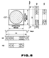
- the horizontal absolute position counter 52h counts clock pulses to produce a count represented as count 0 in Figure 5. It is appreciated that this count represents the absolute position between adjacent horizontal synchronizing signals. Thus, the horizontal absolute position counter 52h counts from a count of 0 to a maximum count x and is reset to a count of 0 in response to the next-occurring horizontal synchronizing signal.
- a scroll control signal is not supplied to the horizontal counter control circuit 53h which detects when the absolute horizontal position count reaches a previously determined value which coincides with the beginning of the effective horizontal range included within the effective picture area.
- the counter control circuit 53h resets the horizontal address counter 55h, thereby permitting the horizontal address counter to count the clock signal supplied to the clock signal input terminal 63.
- the horizontal address counter 55h is incremented in synchronism with the shifting of bits into the shift register 50.
- the count of the horizontal address counter is used as an address in which parallel bits in the shift register 50 are written into and stored in the memory 13.
- the memory address likewise changes to define new storage locations in which the graphic title image data are stored.
- the vertical absolute position counter 52v, the vertical counter control circuit 53v and the vertical address counter 55v function in a substantially similar manner, except that the vertical absolute position counter 52v and the vertical address counter 55v count horizontal synchronizing signals, and the vertical absolute position counter 52v is reset in response to the vertical synchronizing signal. Nevertheless, when the absolute vertical position count reaches a previously determined value, the vertical counter control circuit 53v resets the vertical address counter 55v, thereby enabling the vertical address counter 55v to count horizontal synchronizing signals.
- Each count of the vertical address counter 55v serves as a new address for the memory 13; and it is appreciated that, in one embodiment, the memory 13 may be thought of as a matrix array with each storage location defined by a horizontal address and a vertical address. Thus, successive groups of serialized graphic title image bits are converted to parallel form and are stored at the address then defined by the counts of the horizontal address counter 55h and the vertical address counter 55v.
- Figure 5 illustrates the manner in which the counter control circuits 53h and 53v convert the horizontal and vertical absolute position counts to horizontal and vertical address counts which define the effective horizontal and vertical ranges of the picture area.
- horizontal address counts H0 from, for example, 0 to h and vertical address counts V0 from, for example, 0 to v represent the effective image plane of the video signal.
- the graphic title image data are stored only in those locations in the memory 13 that are included within this effective image plane.
- the horizontal image range includes horizontal counts 0 to h; and the vertical image range includes counts 0 to v.
- the graphic title image data stored in the addressed locations are transferred to the data output port 81 and loaded in parallel into the shift register 50.
- the shift register 50 responds to clock pulses supplied thereto to shift the content thereof serially to the gate circuit 51.
- the successive reading of graphic title image data from the memory 13 to the shift register 50 and the shifting of the contents of the shift register 50 through the gate circuit 51 result in serial graphic title image data corresponding to the graphic information 102 shown in Figure 5.
- This figure represents the juxtaposition of the graphic image and the horizontal and vertical addresses generated by the address counters 55h and 55v.
- the horizontal image range defining circuit 54h detects when the count of the horizontal address counter 55h is within the range 0 to h to supply an enabling signal to the gate circuit 51.
- the vertical image range defining circuit 54v senses when the count of the vertical address counter 55v is within the range 0 to v to supply an enabling signal to the gate circuit 51.
- the gate circuit 51 opens to pass the graphic title image data serially from the shift register 50.
- the passed graphic title image data are modulated with red, green or blue colour signals and supplied from the output terminal 71, 72 or 73 to the converting circuit 15 ( Figure 2).
- the R, G, B graphic title image signals are converted by the converting circuit 15 to luminance and colour difference signals that are supplied to the superimposing circuits 5, 6 and 7.
- the superimpose control signal generator 57 responds to the graphic title image data passed by the gate circuit 51 to supply a blanking signal BLK coincident with the graphic title image signals to the superimposing circuits 5, 6 and 7.
- the superimposing circuits 5, 6 and 7 replace that portion of the video signal then being received from the image processing circuit 4 (that is, the video signal picked up by the CCD 1) with the graphic title image video signals produced by the converting circuit 15.
- graphic title image information is superimposed onto the composite video signal then being produced by the video camera 30.
- a scene which is in the process of being imaged by the CCD 1 has superimposed thereon graphic title image signals such that the video picture derived therefrom, as may be recorded by the VTR 20, contains the superimposed graphic material.
- the graphic title image signals superimposed onto the picked up video signals may be scrolled in the horizontal and vertical direction. That is, the relative position of the graphic title image signals superposed onto the input video signal may be shifted such that when a video picture thereof is displayed, the graphic material derived from the graphic title image signals appears to shift, or scroll, horizontally and vertically.
- this horizontal movement is carried out in the right-to-left direction and the vertical movement is carried out from bottom-to-top of the video picture.
- Horizontal scrolling is achieved by closing the switch 33h
- vertical scrolling is achieved by closing the switch 33v. The manner in which shown such scrolling is carried out now will be described.
- the switch 32 is actuated to supply the memory 13 with the read enable signal.
- the horizontal scroll switch 33h is actuated.
- the scroll control circuit 56 supplied a signal to the horizontal counter control circuit 53h to vary the absolute horizontal position count which is detected for resetting the horizontal address counter 55h.
- the scroll control signal also is supplied to the horizontal image range defining circuit 54h to enable it to vary the beginning of the horizontal gate enabling signal produced thereby, yet permit the horizontal image range defining circuit 54h to terminate that enabling signal when the count of the horizontal absolute position counter 52h reaches the count corresponding to the end of the horizontal image range (represented in Figure 5 as count x - 2).
- the scroll control signal supplied to the horizontal counter control circuit 53h by the scroll control circuit 56 causes the horizontal counter control circuit 53h to vary the absolute horizontal position address count that is detected and used to reset the horizontal address counter 55h by a predetermined number of addresses every m frames. For example, during a particular frame, let is be assumed that the counter control circuit 53h resets the horizontal address counter when the absolute horizontal position count is equal to (x - 4). At that time, the horizontal address count is reset, as represented by counts H1 in Figure 6, and the horizontal image range defining circuit 54h commences the horizontal gate enabling pulse, as represented by pulse h1 in Figure 6.
- the horizontal image range defining circuit 54h terminates the horizontal gate enabling pulse h1, as shown.
- the resultant graphic title image signals which are superimposed onto the input video signal produce an effective image of the type shown at the top of Figure 6.
- the horizontal counter control circuit 53h functions to detect when the absolute horizontal position count is equal to, for example, (x - 6) to reset the horizontal address counter 55h.
- horizontal address counts H2 are generated, resulting in horizontal gate enabling pulse h2.
- the graphic title image data stored at memory locations addressed by horizontal address counts H2 are read therefrom, loaded into the shift register 50 and gated out of the shift register 50 by the gate circuit 51 during the interval defined by horizontal gate enable pulse h2. It is appreciated that this shifting of the horizontal address counts H2 results in a right-to-left shift of the graphic title image information superimposed onto the input video signal and displayed as a video picture.
- the horizontal counter control circuit 53h detects when the absolute horizontal position count is equal to (x - 8) to reset the horizontal address counter 55h. Now, the horizontal address counts appear as counts H3, resulting in the horizontal gate enable pulse shown at h3. This provides a further right-to-left shifting in the graphic title image data read from the memory 13 and superimposed by the gate circuit 51, the converting circuit 15 (FIgure 2) and superimposing circuits 5, 6 and 7 on the input video signal. The graphic material displayed from the superimposed graphic title image signals also appears to shift in the right-to-left direction.
- the foregoing shifting in the absolute horizontal position count which is detected for resetting the horizontal address counter 55h continues by, for example, two address counts (as discussed in the foregoing examples) every m frames. It is appreciated that this shifting may be any desired number of addresses and may be repeated at every m frames or at every m fields, wherein m is an integer. Such shifting in the absolute horizontal position count that is used to reset the horizontal address counter 55h may be achieved by, for example, subtracting a desired count (which may vary every m frames or fields) from the absolute horizontal position count and then detecting when the difference count reaches the value which has been discussed above as the value representing the beginning of the horizontal image range.
- the horizontal address count 2 ( Figure 5) represents the beginning of the horizontal image range
- the horizontal address count is not reset until the absolute horizontal position count has been incremented by that amount which has been subtracted.
- Figure 6 when a large count value is subtracted, the horizontal address counter is reset close to the vicinity of the end of the horizontal image range. As this value is reduced, the resetting of the horizontal address counter shifts towards the beginning of the horizontal image range, as shown in Figure 6.
- the horizontal address counter 55h thereafter may be present to a positive address count other than 0 when a predetermined count of the absolute horizontal position count is detected. Accordingly, when the absolute horizontal position count reaches a count of 2 (which, as shown in Figure 5, had been used previously to reset horizontal address counter 55h), the horizontal address counter 55h now may be preset to a desired count. As a result of this presetting of the horizontal address counter 55h, its count h is reached prior to the time that the absolute horizontal position count reaches the count of (x - 2).
- a horizontal address count h had been used to terminate the horizontal gate enable signal produced by the horizontal image range defining circuit 54h. This same count h may be used to reset the horizontal gate enable signal; but now the resetting of that signal appears to shift in the right-to-left direction, as shown in Figure 6. It is recognized that horizontal address counts Hn are preset to the count (h - 1) when the absolute horizontal position count reaches the count of 2, at which time the horizontal gate enable signal hn is initiated. Then, when the horizontal address count increments to the count of h, the horizontal gate enable signal terminates at the next clock pulse, as shown at hn in Figure 6.
- Figure 6 illustrates the vertical address counts VO which are equal to those used during a graphic title image data write operation and also used during a non-scrolling graphic title image data superposition operation. That is, Figure 6 has been discussed in the case where there is no vertical scrolling of the graphic title image signals.
- the scroll control circuit 56 supplies a scroll control signal to the vertical counter control circuit 53v and also to the vertical image range defining circuit 54v.
- the vertical counter control circuit 53v functions in a manner analogous to that of horizontal counter control circuit 53h to detect the absolute vertical position count reached by the vertical absolute position counter 52v for the purpose of resetting the vertical address counter 55v.
- Figure 7 illustrates the manner in which the vertical address count is reset at different absolute vertical position counts, resulting in a changing of vertical address counts V1, V2, V3, ...Vn.
- the vertical image range defining circuit 54v initiates the vertical gate enable signal, thereby changing the time at which this enable signal begins, as depicted at v1, v2, v3, ...vn in Figure 7.
- the vertical gate enable signal terminates either when the absolute vertical position count reaches a predetermined count, such as the count (y - 1) shown in Figure 5, or when the vertical address count reaches the value v, as represented by vertical gate enable signal vn in Figure 7.
- titler apparatus 12 results in a changing of vertical address counts V by a predetermined amount, such as two counts, every m fields or frames. Consequently, the address locations of the memory 13 which are read during each effective image interval appears to shift in the upward direction; and the graphic title image data read from the memory 13 is gated out of the shift register 50 during the interval determined by vertical gate enable signal v1...vn. As a result, the graphic title image data appears to shift, or scroll, upwardly in the vertical direction, as represented by arrow VSR in Figure 7.
- both the address counters 55h and 55v may be controlled in substantially the same manner, for the purpose of simplification and convenience and in order to avoid duplicate explanation, the following description is directed to controlling the vertical address counter 55v.
- Figure 8 a diagrammatic representation is provided to illustrate that the vertical counter control circuit 53v detects when the absolute vertical position count reaches a previously determined value identifying the beginning, or top, of the vertical image plane to preset the vertical address counter 55v to a desired count. The vertical address counter 55v is then incremented from its preset count until a predetermined address (such as address 0) is reached.
- the vertical image range defining circuit 54v responds to this predetermined address to initiate the vertical gate enable signal.
- This gate enable signal is terminated when the absolute vertical position count supplied to the vertical image range defining circuit 54v reaches a desired count, such as count (y - 1).
- the vertical counter control circuit 53v presets the vertical address counter 55v to a different count at the beginning of the vertical image range, as represented by preset count D + 2. With this different preset count, the vertical address count reaches the predetermined address 0 sooner than had been reached when the count had been preset to the count D. Thus, the vertical address counts appear to be shifted in the upward direction and, additionally, the vertical gate enable signal likewise appears to be enlarged upwardly from the bottom of the vertical image range.
- Figure 8 depicts this upward shifting in the vertical address counts as the vertical address counter 55v is preset to different counts (D, D + 2, D + 4, D + 6, etc.) every m frames (or fields).
- graphic title image date read from the memory 13 appears to be shifted in the upward direction; and the resultant video picture that is derived from this graphic title image data likewise appears to scroll upwardly across the picture area.
- the counter control circuit 53v resets the vertical address counter 55v in response to different absolute vertical position counts, as shown in Figure 9.
- the vertical image range defining circuit 54v responds to a predetermined absolute vertical position count (such as count 2) to initiate the vertical gate enable signal, and then responds to the predetermined vertical address count (for example, count v) to terminate that signal.
- a predetermined absolute vertical position count such as count 2
- the predetermined vertical address count for example, count v
- Figure 9 illustrates, as one example, the resetting of the vertical address counter 55v when the absolute vertical position count reaches a count of, for example, two.
- the vertical gate enable signal produced by the vertical image range defining circuit 54v is coextensive, at this time, with the effective vertical range. If, now the vertical address counter is reset when the vertical absolute position count reaches a count of zero, the graphic title image data stored at locations corresponding to vertical addresses 2 to v are read out and gated through the gate circuit 51.
- the scroll rate or speed at which the graphic title image information appears to move across the video picture area, is a function of the rate at which the horizontal and vertical address counts are changed and the amount of each change. For example, if the address counts are changed by one count every twenty frames, a relatively slow scrolling effect is achieved. This scrolling effect is accelerated if the address counts are changed by one count every frame, or by two counts every four frames, etc.
- the input video signal having the graphic title image signals superimposed thereon are supplied to the viewfinder 40 by the NTSC encoder 8 ( Figure 2).
- a user thus may observe the superimposed graphic information and also be apprised of the particular colour used to modulate that information.
- a change in colour may be made by actuating the switch 34, as discussed above.
- a suitable colour indication may nevertheless be displayed.
- the graphic title image data need not be derived solely by imaging a placard 100, as represented in Figure 1. Rather, graphic video signals may be reproduced by a VTR (or the like) and supplied to the A/D converter 11 ( Figure 2). Also, other techniques may be used to control the horizontal and vertical address counters 55h and 55v so as to vary the interval during which the gate circuit 51 is enabled. Likewise, the full contents of the memory 13 may be loaded into the shift register 50, but only a portion of the graphic title image data in the shift register 50 may be gated out, depending upon the interval of the horizontal and vertical gate enable signals. The result still would achieve a horizontal and vertical scrolling effect of the type discussed above in conjunction with Figures 6 to 9.
Applications Claiming Priority (2)
| Application Number | Priority Date | Filing Date | Title |
|---|---|---|---|
| JP14554/88 | 1988-01-27 | ||
| JP63014554A JP2829958B2 (ja) | 1988-01-27 | 1988-01-27 | タイトル画像挿入装置 |
Publications (3)
| Publication Number | Publication Date |
|---|---|
| EP0326327A2 EP0326327A2 (en) | 1989-08-02 |
| EP0326327A3 EP0326327A3 (en) | 1991-01-02 |
| EP0326327B1 true EP0326327B1 (en) | 1995-01-04 |
Family
ID=11864366
Family Applications (1)
| Application Number | Title | Priority Date | Filing Date |
|---|---|---|---|
| EP89300655A Expired - Lifetime EP0326327B1 (en) | 1988-01-27 | 1989-01-24 | Apparatus for superimposing graphic title image signals onto a video signal |
Country Status (5)
| Country | Link |
|---|---|
| US (1) | US4999709A (ja) |
| EP (1) | EP0326327B1 (ja) |
| JP (1) | JP2829958B2 (ja) |
| KR (1) | KR970010196B1 (ja) |
| DE (1) | DE68920337T2 (ja) |
Families Citing this family (53)
| Publication number | Priority date | Publication date | Assignee | Title |
|---|---|---|---|---|
| JP2653118B2 (ja) * | 1988-08-23 | 1997-09-10 | ソニー株式会社 | カメラ一体型ビデオレコーダ |
| JP2595088B2 (ja) * | 1989-04-10 | 1997-03-26 | 三菱電機株式会社 | 文字・パターン記憶再生装置 |
| US5515101A (en) * | 1989-04-28 | 1996-05-07 | Minolta Co., Ltd. | Title generator for a video camera |
| KR0139820B1 (ko) * | 1989-11-13 | 1998-06-15 | 이헌조 | 영상자막기의 녹화제어 시스템 |
| WO1991007739A1 (en) * | 1989-11-14 | 1991-05-30 | Imtech International, Inc. | Moving message display method and apparatus |
| KR910013870A (ko) * | 1989-12-31 | 1991-08-08 | 강진구 | 캠코더의 편집시스템 |
| JP2776934B2 (ja) * | 1990-01-10 | 1998-07-16 | 株式会社日立製作所 | 映像信号処理装置 |
| JPH03272278A (ja) * | 1990-03-22 | 1991-12-03 | Canon Inc | 画像信号処理回路 |
| US5274463A (en) * | 1990-03-27 | 1993-12-28 | Sony Corporation | Still picture storing and sequencing apparatus |
| JP2952955B2 (ja) * | 1990-04-19 | 1999-09-27 | ソニー株式会社 | 画像作成装置 |
| KR100216162B1 (ko) * | 1990-06-26 | 1999-08-16 | 다카노 야스아키 | 영상 신호를 합성하기 위한 촬상장치 및 영상 신호 처리 시스템 |
| CA2090124A1 (en) * | 1990-08-21 | 1992-02-22 | Paul Noble | Video moving message display |
| JPH0771203B2 (ja) * | 1990-09-18 | 1995-07-31 | キヤノン株式会社 | 信号記録装置及び信号処理装置 |
| US5426731A (en) * | 1990-11-09 | 1995-06-20 | Fuji Photo Film Co., Ltd. | Apparatus for processing signals representative of a computer graphics image and a real image |
| EP0484981B1 (en) * | 1990-11-09 | 1998-07-08 | Fuji Photo Film Co., Ltd. | Image data processing apparatus |
| JP2740364B2 (ja) * | 1991-04-01 | 1998-04-15 | 三洋電機株式会社 | タイトル画像挿入装置 |
| JPH04312077A (ja) * | 1991-04-11 | 1992-11-04 | Canon Inc | ディジタルスーパーインポーズ装置 |
| KR940001982B1 (ko) * | 1991-04-12 | 1994-03-12 | 삼성전자 주식회사 | 타이틀 편집 기능을 갖는 리모콘 |
| EP0510642B1 (en) * | 1991-04-25 | 1998-07-22 | Canon Kabushiki Kaisha | Image super imposing system for different display aspect ratios |
| KR940008581B1 (ko) * | 1991-05-03 | 1994-09-24 | 삼정전자 주식회사 | 문자 편집장치 및 방법 |
| US5805237A (en) * | 1991-05-20 | 1998-09-08 | Canon Kabushiki Kaisha | Image processing apparatus with a function of superimposing a binary image on another image |
| DE4131621C1 (en) * | 1991-09-23 | 1992-10-08 | Siemens Ag, 8000 Muenchen, De | Video camera system with fade-in markings - mixes in centering cross into video picture for focusing or aligning camera |
| US5392069A (en) * | 1992-06-11 | 1995-02-21 | Canon Kabushiki Kaisha | Image processing apparatus which can process a plurality of kinds of images having different aspect ratios |
| TW371340B (en) * | 1992-10-09 | 1999-10-01 | Hudson Soft Co Ltd | Image processing system |
| WO1994009457A1 (en) * | 1992-10-13 | 1994-04-28 | Gilbarco Inc. | Transaction apparatus |
| US7721307B2 (en) | 1992-12-09 | 2010-05-18 | Comcast Ip Holdings I, Llc | Method and apparatus for targeting of interactive virtual objects |
| US5541666A (en) * | 1994-07-06 | 1996-07-30 | General Instrument | Method and apparatus for overlaying digitally generated graphics over an analog video signal |
| JPH0879626A (ja) * | 1994-09-05 | 1996-03-22 | Sony Corp | ビデオ装置 |
| US5717468A (en) * | 1994-12-02 | 1998-02-10 | International Business Machines Corporation | System and method for dynamically recording and displaying comments for a video movie |
| US5912700A (en) * | 1996-01-10 | 1999-06-15 | Fox Sports Productions, Inc. | System for enhancing the television presentation of an object at a sporting event |
| JP3326669B2 (ja) * | 1995-06-30 | 2002-09-24 | ソニー株式会社 | データ再生装置 |
| FR2747000B1 (fr) * | 1996-03-26 | 1998-06-19 | Sgs Thomson Microelectronics | Preamplificateur video avec insertion de donnees |
| US5917553A (en) * | 1996-10-22 | 1999-06-29 | Fox Sports Productions Inc. | Method and apparatus for enhancing the broadcast of a live event |
| US6535681B2 (en) * | 2001-06-19 | 2003-03-18 | Lucent Technologies Inc. | Fiber-optic cable routing and bend limiting device and system |
| US5956458A (en) * | 1996-11-07 | 1999-09-21 | Sharp Laboratories Of America, Inc. | System and method for determining representative frames of video captured by a video camera |
| US5953077A (en) * | 1997-01-17 | 1999-09-14 | Fox Sports Productions, Inc. | System for displaying an object that is not visible to a camera |
| US6252632B1 (en) | 1997-01-17 | 2001-06-26 | Fox Sports Productions, Inc. | System for enhancing a video presentation |
| US6614988B1 (en) * | 1997-03-28 | 2003-09-02 | Sharp Laboratories Of America, Inc. | Natural language labeling of video using multiple words |
| US6052629A (en) | 1997-07-18 | 2000-04-18 | Gilbarco Inc. | Internet capable browser dispenser architecture |
| US6133946A (en) * | 1998-01-06 | 2000-10-17 | Sportvision, Inc. | System for determining the position of an object |
| US6229550B1 (en) | 1998-09-04 | 2001-05-08 | Sportvision, Inc. | Blending a graphic |
| US6266100B1 (en) | 1998-09-04 | 2001-07-24 | Sportvision, Inc. | System for enhancing a video presentation of a live event |
| US6466275B1 (en) | 1999-04-16 | 2002-10-15 | Sportvision, Inc. | Enhancing a video of an event at a remote location using data acquired at the event |
| US7075556B1 (en) * | 1999-10-21 | 2006-07-11 | Sportvision, Inc. | Telestrator system |
| US6909438B1 (en) | 2000-02-04 | 2005-06-21 | Sportvision, Inc. | Video compositor |
| JP2003195852A (ja) * | 2001-12-28 | 2003-07-09 | Canon Inc | 画像処理装置 |
| JP2006157697A (ja) * | 2004-11-30 | 2006-06-15 | Orion Denki Kk | 録画再生装置 |
| JP4641900B2 (ja) * | 2005-08-24 | 2011-03-02 | ルネサスエレクトロニクス株式会社 | 半導体装置及びテスト方法 |
| US9215383B2 (en) | 2011-08-05 | 2015-12-15 | Sportsvision, Inc. | System for enhancing video from a mobile camera |
| USD855944S1 (en) * | 2015-12-14 | 2019-08-13 | Gerald E. Clear | Garment with side pocket |
| USD819092S1 (en) | 2016-03-30 | 2018-05-29 | Whirlpool Corporation | Refrigerator interior with color |
| KR102610058B1 (ko) * | 2017-01-10 | 2023-12-06 | 삼성전자주식회사 | 프로세스의 권한 상승을 검출하는 전자 장치 및 저장 매체 |
| USD952007S1 (en) | 2019-12-20 | 2022-05-17 | Whirlpool Corporation | Food storage appliance |
Citations (1)
| Publication number | Priority date | Publication date | Assignee | Title |
|---|---|---|---|---|
| EP0139095A2 (en) * | 1983-08-16 | 1985-05-02 | International Business Machines Corporation | Display selection in a raster scan display system |
Family Cites Families (12)
| Publication number | Priority date | Publication date | Assignee | Title |
|---|---|---|---|---|
| GB1595964A (en) * | 1977-03-17 | 1981-08-19 | Micro Consultants Ltd Tv | Special effects generator |
| JPS5922572U (ja) * | 1982-07-30 | 1984-02-10 | 日本テレビジヨン工業株式会社 | テロツプ装置 |
| US4533952A (en) * | 1982-10-22 | 1985-08-06 | Digital Services Corporation | Digital video special effects system |
| JPH0773343B2 (ja) * | 1982-11-04 | 1995-08-02 | 株式会社ニコン | 携帯用テレビジョンカメラ |
| JPS59159196A (ja) * | 1983-02-24 | 1984-09-08 | インタ−ナシヨナル ビジネス マシ−ンズ コ−ポレ−シヨン | グラフイツク・デイスプレイ・システム |
| JPS6016777A (ja) * | 1983-07-08 | 1985-01-28 | Victor Co Of Japan Ltd | 文字信号発生装置 |
| JPS6046686A (ja) * | 1983-08-24 | 1985-03-13 | Matsushita Electric Ind Co Ltd | カラ−ビデオカメラ |
| JPS60182879A (ja) * | 1984-03-01 | 1985-09-18 | Olympus Optical Co Ltd | ビデオカメラ装置 |
| JPS6194087A (ja) * | 1984-10-15 | 1986-05-12 | 松下電器産業株式会社 | 表示装置 |
| JPS61151691A (ja) * | 1984-12-20 | 1986-07-10 | インタ−ナショナル ビジネス マシ−ンズ コ−ポレ−ション | 表示装置 |
| JPS61277991A (ja) * | 1985-05-30 | 1986-12-08 | インタ−ナショナル・ビジネス・マシ−ンズ・コ−ポレ−ション | スムース・スクロール方法 |
| IT1215206B (it) * | 1986-12-18 | 1990-01-31 | Sip | Modulo interfaccia per la sovrapposizione di caratteri alfanumerici e segnale video rgb |
-
1988
- 1988-01-27 JP JP63014554A patent/JP2829958B2/ja not_active Expired - Lifetime
-
1989
- 1989-01-19 US US07/299,063 patent/US4999709A/en not_active Expired - Lifetime
- 1989-01-24 DE DE68920337T patent/DE68920337T2/de not_active Expired - Lifetime
- 1989-01-24 EP EP89300655A patent/EP0326327B1/en not_active Expired - Lifetime
- 1989-01-26 KR KR89000790A patent/KR970010196B1/ko not_active IP Right Cessation
Patent Citations (1)
| Publication number | Priority date | Publication date | Assignee | Title |
|---|---|---|---|---|
| EP0139095A2 (en) * | 1983-08-16 | 1985-05-02 | International Business Machines Corporation | Display selection in a raster scan display system |
Also Published As
| Publication number | Publication date |
|---|---|
| EP0326327A2 (en) | 1989-08-02 |
| JPH01191581A (ja) | 1989-08-01 |
| DE68920337D1 (de) | 1995-02-16 |
| KR970010196B1 (en) | 1997-06-23 |
| EP0326327A3 (en) | 1991-01-02 |
| DE68920337T2 (de) | 1995-06-22 |
| US4999709A (en) | 1991-03-12 |
| JP2829958B2 (ja) | 1998-12-02 |
| KR890012486A (ko) | 1989-08-26 |
Similar Documents
| Publication | Publication Date | Title |
|---|---|---|
| EP0326327B1 (en) | Apparatus for superimposing graphic title image signals onto a video signal | |
| US5450129A (en) | Image processing apparatus for converting different television standard signals | |
| CA2127608C (en) | Monitor screen-integrated video camera | |
| US4953025A (en) | Apparatus for defining an effective picture area of a high definition video signal when displayed on a screen with a different aspect ratio | |
| JPS58184993A (ja) | ビデオ信号発生システム | |
| EP0423961B1 (en) | Video special effects apparatus | |
| US4713693A (en) | Composite single video image system and method utilizing video peak storing memory | |
| JP2776934B2 (ja) | 映像信号処理装置 | |
| US5175624A (en) | Video system having image combining function | |
| KR19990036087A (ko) | 연결 리스트 구조 온스크린 디스플레이 | |
| KR940001439B1 (ko) | 자막정보 중첩회로 | |
| EP0346028B1 (en) | Video signal display apparatus | |
| EP0501462B1 (en) | Display apparatus | |
| US5625741A (en) | Video signal recording apparatus | |
| EP0508785B1 (en) | Scrolling superimposition of generated title | |
| JPH0444472B2 (ja) | ||
| JP2823234B2 (ja) | 画面表示装置 | |
| JP3463429B2 (ja) | テレビジョン受信機 | |
| JPH0540618Y2 (ja) | ||
| JP2781924B2 (ja) | スーパーインポーズ装置 | |
| KR940006015B1 (ko) | 화면편집장치 | |
| JPH0548970A (ja) | 映像信号処理装置 | |
| JPH01176172A (ja) | タイトル画像発生装置 | |
| JPS5930375A (ja) | 撮像システム | |
| JPH04304787A (ja) | タイトル画像挿入装置 |
Legal Events
| Date | Code | Title | Description |
|---|---|---|---|
| PUAI | Public reference made under article 153(3) epc to a published international application that has entered the european phase |
Free format text: ORIGINAL CODE: 0009012 |
|
| AK | Designated contracting states |
Kind code of ref document: A2 Designated state(s): DE FR GB NL |
|
| PUAL | Search report despatched |
Free format text: ORIGINAL CODE: 0009013 |
|
| AK | Designated contracting states |
Kind code of ref document: A3 Designated state(s): DE FR GB NL |
|
| 17P | Request for examination filed |
Effective date: 19910424 |
|
| 17Q | First examination report despatched |
Effective date: 19930204 |
|
| GRAA | (expected) grant |
Free format text: ORIGINAL CODE: 0009210 |
|
| AK | Designated contracting states |
Kind code of ref document: B1 Designated state(s): DE FR GB NL |
|
| REF | Corresponds to: |
Ref document number: 68920337 Country of ref document: DE Date of ref document: 19950216 |
|
| ET | Fr: translation filed | ||
| PLBE | No opposition filed within time limit |
Free format text: ORIGINAL CODE: 0009261 |
|
| STAA | Information on the status of an ep patent application or granted ep patent |
Free format text: STATUS: NO OPPOSITION FILED WITHIN TIME LIMIT |
|
| 26N | No opposition filed | ||
| REG | Reference to a national code |
Ref country code: GB Ref legal event code: IF02 |
|
| PGFP | Annual fee paid to national office [announced via postgrant information from national office to epo] |
Ref country code: GB Payment date: 20080123 Year of fee payment: 20 Ref country code: DE Payment date: 20080117 Year of fee payment: 20 Ref country code: NL Payment date: 20071219 Year of fee payment: 20 |
|
| PGFP | Annual fee paid to national office [announced via postgrant information from national office to epo] |
Ref country code: FR Payment date: 20080108 Year of fee payment: 20 |
|
| REG | Reference to a national code |
Ref country code: GB Ref legal event code: PE20 Expiry date: 20090123 |
|
| NLV7 | Nl: ceased due to reaching the maximum lifetime of a patent |
Effective date: 20090124 |
|
| PG25 | Lapsed in a contracting state [announced via postgrant information from national office to epo] |
Ref country code: NL Free format text: LAPSE BECAUSE OF EXPIRATION OF PROTECTION Effective date: 20090124 |
|
| PG25 | Lapsed in a contracting state [announced via postgrant information from national office to epo] |
Ref country code: GB Free format text: LAPSE BECAUSE OF EXPIRATION OF PROTECTION Effective date: 20090123 |