EP0325599B1 - Dispositif pour remplir de toner un reservoir prevu a cet effet depuis un bac de transfert - Google Patents
Dispositif pour remplir de toner un reservoir prevu a cet effet depuis un bac de transfert Download PDFInfo
- Publication number
- EP0325599B1 EP0325599B1 EP87906158A EP87906158A EP0325599B1 EP 0325599 B1 EP0325599 B1 EP 0325599B1 EP 87906158 A EP87906158 A EP 87906158A EP 87906158 A EP87906158 A EP 87906158A EP 0325599 B1 EP0325599 B1 EP 0325599B1
- Authority
- EP
- European Patent Office
- Prior art keywords
- toner
- filter
- suction
- intake
- transport container
- Prior art date
- Legal status (The legal status is an assumption and is not a legal conclusion. Google has not performed a legal analysis and makes no representation as to the accuracy of the status listed.)
- Expired - Lifetime
Links
Images

Classifications
-
- B—PERFORMING OPERATIONS; TRANSPORTING
- B65—CONVEYING; PACKING; STORING; HANDLING THIN OR FILAMENTARY MATERIAL
- B65G—TRANSPORT OR STORAGE DEVICES, e.g. CONVEYORS FOR LOADING OR TIPPING, SHOP CONVEYOR SYSTEMS OR PNEUMATIC TUBE CONVEYORS
- B65G53/00—Conveying materials in bulk through troughs, pipes or tubes by floating the materials or by flow of gas, liquid or foam
- B65G53/34—Details
- B65G53/40—Feeding or discharging devices
- B65G53/42—Nozzles
-
- G—PHYSICS
- G03—PHOTOGRAPHY; CINEMATOGRAPHY; ANALOGOUS TECHNIQUES USING WAVES OTHER THAN OPTICAL WAVES; ELECTROGRAPHY; HOLOGRAPHY
- G03G—ELECTROGRAPHY; ELECTROPHOTOGRAPHY; MAGNETOGRAPHY
- G03G15/00—Apparatus for electrographic processes using a charge pattern
- G03G15/06—Apparatus for electrographic processes using a charge pattern for developing
- G03G15/08—Apparatus for electrographic processes using a charge pattern for developing using a solid developer, e.g. powder developer
- G03G15/0822—Arrangements for preparing, mixing, supplying or dispensing developer
- G03G15/0865—Arrangements for supplying new developer
-
- G—PHYSICS
- G03—PHOTOGRAPHY; CINEMATOGRAPHY; ANALOGOUS TECHNIQUES USING WAVES OTHER THAN OPTICAL WAVES; ELECTROGRAPHY; HOLOGRAPHY
- G03G—ELECTROGRAPHY; ELECTROPHOTOGRAPHY; MAGNETOGRAPHY
- G03G15/00—Apparatus for electrographic processes using a charge pattern
- G03G15/06—Apparatus for electrographic processes using a charge pattern for developing
- G03G15/08—Apparatus for electrographic processes using a charge pattern for developing using a solid developer, e.g. powder developer
- G03G15/0822—Arrangements for preparing, mixing, supplying or dispensing developer
- G03G15/0865—Arrangements for supplying new developer
- G03G15/0867—Arrangements for supplying new developer cylindrical developer cartridges, e.g. toner bottles for the developer replenishing opening
- G03G15/087—Developer cartridges having a longitudinal rotational axis, around which at least one part is rotated when mounting or using the cartridge
-
- G—PHYSICS
- G03—PHOTOGRAPHY; CINEMATOGRAPHY; ANALOGOUS TECHNIQUES USING WAVES OTHER THAN OPTICAL WAVES; ELECTROGRAPHY; HOLOGRAPHY
- G03G—ELECTROGRAPHY; ELECTROPHOTOGRAPHY; MAGNETOGRAPHY
- G03G15/00—Apparatus for electrographic processes using a charge pattern
- G03G15/06—Apparatus for electrographic processes using a charge pattern for developing
- G03G15/08—Apparatus for electrographic processes using a charge pattern for developing using a solid developer, e.g. powder developer
- G03G15/0894—Reconditioning of the developer unit, i.e. reusing or recycling parts of the unit, e.g. resealing of the unit before refilling with toner
-
- G—PHYSICS
- G03—PHOTOGRAPHY; CINEMATOGRAPHY; ANALOGOUS TECHNIQUES USING WAVES OTHER THAN OPTICAL WAVES; ELECTROGRAPHY; HOLOGRAPHY
- G03G—ELECTROGRAPHY; ELECTROPHOTOGRAPHY; MAGNETOGRAPHY
- G03G2215/00—Apparatus for electrophotographic processes
- G03G2215/06—Developing structures, details
- G03G2215/066—Toner cartridge or other attachable and detachable container for supplying developer material to replace the used material
- G03G2215/0663—Toner cartridge or other attachable and detachable container for supplying developer material to replace the used material having a longitudinal rotational axis, around which at least one part is rotated when mounting or using the cartridge
- G03G2215/0678—Bottle shaped container having a bottle neck for toner discharge
-
- G—PHYSICS
- G03—PHOTOGRAPHY; CINEMATOGRAPHY; ANALOGOUS TECHNIQUES USING WAVES OTHER THAN OPTICAL WAVES; ELECTROGRAPHY; HOLOGRAPHY
- G03G—ELECTROGRAPHY; ELECTROPHOTOGRAPHY; MAGNETOGRAPHY
- G03G2215/00—Apparatus for electrophotographic processes
- G03G2215/06—Developing structures, details
- G03G2215/066—Toner cartridge or other attachable and detachable container for supplying developer material to replace the used material
- G03G2215/069—Toner cartridge or other attachable and detachable container for supplying developer material to replace the used material using a sealing member to be ruptured or cut
-
- Y—GENERAL TAGGING OF NEW TECHNOLOGICAL DEVELOPMENTS; GENERAL TAGGING OF CROSS-SECTIONAL TECHNOLOGIES SPANNING OVER SEVERAL SECTIONS OF THE IPC; TECHNICAL SUBJECTS COVERED BY FORMER USPC CROSS-REFERENCE ART COLLECTIONS [XRACs] AND DIGESTS
- Y10—TECHNICAL SUBJECTS COVERED BY FORMER USPC
- Y10S—TECHNICAL SUBJECTS COVERED BY FORMER USPC CROSS-REFERENCE ART COLLECTIONS [XRACs] AND DIGESTS
- Y10S222/00—Dispensing
- Y10S222/01—Xerography
Definitions
- the invention relates to a device according to the preamble of patent claim 1.
- charge images are recorded on a recording medium e.g. produced directly on an intermediate carrier (photoconductor drum) or directly on special paper and then colored with a black powder (toner) in a developer station.
- a recording medium e.g. produced directly on an intermediate carrier (photoconductor drum) or directly on special paper and then colored with a black powder (toner) in a developer station.
- an intermediate carrier is used, this toner image is then transferred to normal paper and fixed thereon.
- a two-component developer consisting of ferromagnetic carrier particles and toner particles is generally used for the development.
- the developer is guided past the charge image on the intermediate carrier by means of a magnetic brush arrangement, to which the toner sticks due to electrostatic forces.
- An electrophotographic copier that develops charge images according to the specified principle is e.g. known from DE-AS 21 66 667.
- the toner concentration in the developer mixture of the developer station decreases continuously. It is therefore necessary to continuously add new toner to the developer mixture. Since the toner consumption per unit of time is very high in the case of fast copying machines and high-performance data printers, a spacious toner reservoir is used in such machines in order to avoid downtimes by refilling the toner. When this toner reservoir is empty, the toner that is usually supplied in handy containers, filled in the storage container. It is important to fill the toner from the container into the storage container in such a way that no toner is spilled and the environment is thereby contaminated.
- a device for filling and sieving toner from a container into a toner reservoir is known.
- the toner located in a transport container namely a toner bottle
- a storage container in that the toner bottle is slipped into a filling opening of the storage container.
- a sieve basket In the area of the filling opening there is a sieve basket, which is closed off from the storage container by a sieve and which is connected to an electrical vibrating device which can be triggered if necessary.
- the vibrating device is triggered by opening the cover closing the filler opening.
- the object of the invention is to design a device of the type mentioned so that the toner from a simple, inexpensive transport container can be transferred into a device-side storage container with a large capacity without toner hardening occurring or toner spilling.
- the toner is advantageously removed from a transport container, namely the toner bottle, by suction via a flexible line by means of negative pressure.
- a suction nozzle is provided which contains an inner tube which is open in the suction area and an outer tube which surrounds the inner tube at a distance.
- the outer tube is open at the top and thus forms an air intake opening.
- toner inlet openings are arranged on the outer tube.
- the negative pressure generated by a suction fan causes an air flow through the outer tube and the inner tube. The toner is entrained into the inner tube through the toner inlet openings.
- the toner reaches a storage container via a flexible line, which is divided into a settling chamber and a suction chamber separated from the settling chamber via a filter.
- the suction chamber is connected to a vacuum pump, which creates a vacuum, which causes the toner to settle on the filter of the sedimentation chamber.
- the filter is designed such that it bulges under the effect of the air flow flowing through it, on the other hand bulges back when the air flow is interrupted.
- the toner adhering to it flakes off and falls into the settling space below.
- a screw conveyor which doses the toner to the developer station of the printer.
- one or more weights can be arranged on the filter in one embodiment of the invention.
- a grating is provided in relation to the suction space.
- a flexible network is arranged instead of the grid.
- the weight is not assigned to the filter but to this network, so that the filter is not mechanically loaded by the weights.
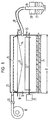
- a toner reservoir 10 from which the toner is fed to a developer station 11 for developing charge images.
- the toner reservoir 10 has approximately the width of the developer station 11, which corresponds approximately to the printing width, and is divided into a settling chamber 12 and a suction chamber 13.
- the chambers are separated from one another by a filter 14 which is made of flexible material.
- the filter 14 is closed off with respect to the suction space 13 by a grid 15.
- the openings of the grid can be arranged and dimensioned according to the desired pressure distribution distribution.
- the suction chamber 13 is connected to an electromotive vacuum pump in the form of a suction fan 16.
- the settling chamber 12 has a connecting piece 17 to which a flexible pipeline 18 is connected, which in turn is connected to a suction nozzle 19. This serves to transfer the toner from a toner transport container 20 (toner bottle) into the toner storage container 10.
- the flexible suction line 18 with the suction nozzle 19 is inserted into the toner bottle and then the suction blower 16 is actuated.
- the negative pressure generated in the suction chamber 13 generates a corresponding negative pressure in the settling chamber 12, as a result of which the toner 21 is sucked into the settling chamber 12 according to the vacuum cleaner principle.
- the toner settles on the filter 14 and falls into the settling chamber 12.
- a mixing device 22 which is driven by a motor 23.
- a metering device In the lower area of the conically shaped settling chamber 12 there is a metering device, likewise driven by the motor 23, in the form of two foam rollers 24 driven in opposite directions. These foam rollers 24, if necessary, transport the toner to the developer station 11 depending on the level detected by a level sensor 25.
- the filter 14 used for toner retention is elastic and bulges upwards when the suction fan 16 is switched on and lies against the semicircular grid 15. If the suction fan 16 is switched off or the air flow is interrupted via a vacuum valve 26, the filter swings back into the starting position shown in FIG. 1 under the effect of the weights 27 arranged on the surface of the filter 14 - only one of which is shown here . As a result of the change in shape of the filter surface caused thereby, the toner adhering to it flakes off and falls into the settling space 12 underneath.
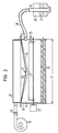
- a likewise elastic net 28 for receiving the weights 27 is arranged above the flexible filter 14.
- the network 28 can be arranged instead of the grid 15 of the embodiment according to FIG. 1. Since the network 28 receives the weights 27, the sensitive filter 14 is not additionally loaded by the weights 27.
- the suction nozzle 19 shown in section in FIG. 3 is used to suck the toner 21 out of the toner bottle 20. It contains an inner tube 29 which is wedge-shaped at its lower end and which is connected to the flexible suction tube 18 and has suction openings 30 for the toner .
- the inner tube 29 is completely surrounded by an outer tube 31 which is arranged at a distance and which on the one hand has an air intake opening 32 opening to the surroundings at its upper part and on the other hand at its tip in the suction area toner inlet openings 33.
- the distance and the guidance of the inner tube 29 to the outer tube 31 becomes by means of spacer elements, not shown here, which, for example can consist of three foam strips evenly distributed around the circumference.
- the toner inlet openings 33 can be covered by a toner screen 34 covering the suction area of the suction nozzle.
- the device shown in FIG. 3 operates as follows: the toner bottle 20, which is conical at its bottom area and whose inlet opening 35 is closed by a lid, is first latched in a holding device 36 receiving the toner bottle, on the bottom of which a vibrating device 37 in the form, for example of a balancing motor.
- the toner bottle 20 is designed or locked in the holding device 36 in such a way that the suction nozzle 19 inserted for suction with its suction area at the deepest point of the toner bottle 20 - namely the conically shaped, recessed part - comes to rest.
- a seal 38 assigned to the suction nozzle 19, for example, provides a corresponding seal in the area of the filler neck 35.
- This seal can be designed like a film and seal the container.
- the seal is perforated using the suction nozzle.
- the toner 21 After switching on the vibrating device 37 by actuating a balancing motor, the toner 21 first migrates into the area of the toner inlet openings 33 with the toner screen 34. Then it passes through the screen into the space between the inner tube 39 and the outer tube 31, specifically in the area of the openings 10 of the Inner tube. After switching on the suction blower 16, the toner is caught by the air flow (arrows) which is drawn in from above and migrates via the flexible line 18 into the settling chamber 12.
Landscapes
- Physics & Mathematics (AREA)
- General Physics & Mathematics (AREA)
- Engineering & Computer Science (AREA)
- Mechanical Engineering (AREA)
- Life Sciences & Earth Sciences (AREA)
- Sustainable Development (AREA)
- Dry Development In Electrophotography (AREA)
- Basic Packing Technique (AREA)
- Cleaning In Electrography (AREA)
Abstract
Claims (8)
Applications Claiming Priority (2)
| Application Number | Priority Date | Filing Date | Title |
|---|---|---|---|
| DE3633599 | 1986-10-02 | ||
| DE19863633599 DE3633599A1 (de) | 1986-10-02 | 1986-10-02 | Vorrichtung zum einfuellen von toner aus einem transportbehaelter in einen tonervorratsbehaelter |
Publications (2)
| Publication Number | Publication Date |
|---|---|
| EP0325599A1 EP0325599A1 (fr) | 1989-08-02 |
| EP0325599B1 true EP0325599B1 (fr) | 1991-10-23 |
Family
ID=6310922
Family Applications (1)
| Application Number | Title | Priority Date | Filing Date |
|---|---|---|---|
| EP87906158A Expired - Lifetime EP0325599B1 (fr) | 1986-10-02 | 1987-09-25 | Dispositif pour remplir de toner un reservoir prevu a cet effet depuis un bac de transfert |
Country Status (5)
| Country | Link |
|---|---|
| US (1) | US4945956A (fr) |
| EP (1) | EP0325599B1 (fr) |
| JP (1) | JP2677575B2 (fr) |
| DE (2) | DE3633599A1 (fr) |
| WO (1) | WO1988002503A1 (fr) |
Families Citing this family (37)
| Publication number | Priority date | Publication date | Assignee | Title |
|---|---|---|---|---|
| US5253683A (en) * | 1989-10-23 | 1993-10-19 | Tools For Bending, Inc. | Method and apparatus for dispensing desiccant materials into window spacer frames |
| US5263518A (en) * | 1990-08-16 | 1993-11-23 | Applied Materials, Inc. | Method and apparatus for reducing particulate generation caused by door or cover flexing on high vacuum equipment |
| DE4124912A1 (de) * | 1991-07-26 | 1993-01-28 | Henkel Kgaa | Vorrichtung und verfahren zur pulverdosierung direkt aus dem verkaufsgebinde |
| DE4124881C2 (de) * | 1991-07-26 | 1994-05-26 | Henkel Kgaa | Vorrichtung zum Ansetzen einer Stammlauge |
| DE4124911A1 (de) * | 1991-07-26 | 1993-01-28 | Henkel Kgaa | Vorrichtung zur aufnahme eines pulvergebindes |
| US5243388A (en) * | 1991-09-05 | 1993-09-07 | Xerox Corporation | System for cleaning the developer unit in an electronic reprographic printing system |
| JPH05204244A (ja) * | 1992-01-23 | 1993-08-13 | Ricoh Co Ltd | 画像形成装置 |
| US5323819A (en) * | 1993-01-07 | 1994-06-28 | Shade Charles L | Overhead vacuum assembly for recovering, storing and dispensing flowable packaging materials |
| US5487417A (en) * | 1993-09-03 | 1996-01-30 | Toshiba Battery Co., Ltd. | Electrolyte injection apparatus |
| NL9302145A (nl) * | 1993-12-09 | 1995-07-03 | Oce Nederland Bv | Transportinrichting voor ontwikkelpoeder. |
| US5570170A (en) * | 1993-12-27 | 1996-10-29 | Moore Business Forms, Inc. | Electrostatic printing apparatus with a hopper and applicator roller with method of applying toner to and declumping the applicator roller |
| US5382117A (en) * | 1994-03-28 | 1995-01-17 | Henkel Kommanditgesellschaft Auf Aktien | Apparatus for holding a powder container |
| US5515663A (en) * | 1994-04-06 | 1996-05-14 | Nu-Kote International, Inc. | Method of refilling ink-jet printer cartridges |
| US5500122A (en) * | 1994-05-11 | 1996-03-19 | Uop | Stacked fluid-separation membrane disk module assemblies |
| US5536405A (en) * | 1994-05-11 | 1996-07-16 | Uop | Stacked membrane disk assemblies for fluid separations |
| US5520807A (en) * | 1994-05-11 | 1996-05-28 | Uop | Stacked fluid-separation membrane disk module assemblies |
| DE59601629D1 (de) * | 1995-10-31 | 1999-05-12 | Oce Printing Systems Gmbh | Tonerzuführeinrichtung für eine entwicklerstation eines druck- oder kopiergerätes |
| DE19541062A1 (de) * | 1995-11-03 | 1996-09-26 | Siemens Nixdorf Inf Syst | Entwicklerstation für ein elektrografisches Druck- oder Kopiergerät |
| DE19642570B4 (de) | 1996-10-15 | 2007-08-16 | OCé PRINTING SYSTEMS GMBH | Vorrichtungen zur Tonerzuführung |
| DE19652860C2 (de) * | 1996-12-18 | 2002-03-21 | Oce Printing Systems Gmbh | Vorrichtung zum Fördern von Tonermaterial aus einem Vorratsbehälter |
| JP4537509B2 (ja) * | 1998-05-07 | 2010-09-01 | 株式会社リコー | 画像形成装置 |
| US6398462B1 (en) * | 1998-06-03 | 2002-06-04 | Nordson Corporation | Powder transfer apparatus having powder fluidizing tube |
| DE19857257B4 (de) * | 1998-12-11 | 2006-12-07 | OCé PRINTING SYSTEMS GMBH | Entwicklungsvorrichtung mit Tonersprüheinrichtung, deren Gemischstrom auf einen Auftragsbereich schräg auftrifft |
| US6678492B1 (en) | 1998-12-22 | 2004-01-13 | Ricoh Company, Ltd. | Toner container and toner delivery apparatus |
| JP3935666B2 (ja) * | 1999-09-30 | 2007-06-27 | 株式会社リコー | ノズル、トナー移送装置および画像形成装置 |
| CN1900837B (zh) | 2000-02-17 | 2012-10-03 | 株式会社理光 | 墨粉收纳容器、补给墨粉的方法及墨粉补给装置 |
| US7619130B2 (en) * | 2000-07-18 | 2009-11-17 | Coloplast A/S | Multi-layer wound dressing formed as a single unit |
| JP3958511B2 (ja) * | 2000-09-28 | 2007-08-15 | 株式会社リコー | トナー補給装置および画像形成装置 |
| EP1626315A3 (fr) * | 2001-01-31 | 2006-08-02 | Ricoh Company, Ltd. | Récipient de toner et dispositif de formation d'images avec celui-ci |
| JP4064646B2 (ja) * | 2001-06-29 | 2008-03-19 | 三菱重工業株式会社 | 放射性物質の密閉容器、密閉容器の密閉溶接方法、および密閉溶接方法に用いる排気装置 |
| JP2005107111A (ja) * | 2003-09-30 | 2005-04-21 | Brother Ind Ltd | 現像剤の除去方法および除去装置 |
| EP1584990A1 (fr) * | 2004-04-05 | 2005-10-12 | Ricoh Co., Ltd. | Dispositif d'alimentation en toner avec alimentation de gaz |
| EP1785780B1 (fr) * | 2005-11-09 | 2011-03-09 | Ricoh Company, Ltd. | Récipient de remplissage de développateur a deux composants et méthode de remplissage |
| JP5831857B2 (ja) * | 2012-01-24 | 2015-12-09 | 株式会社サンギ | 粉体分散装置、微粉体生成方法 |
| WO2017194138A1 (fr) * | 2016-05-12 | 2017-11-16 | Hewlett-Packard Development Company, L.P. | Récipient de matériau de construction et structure de tube de collecte |
| CN108107695B (zh) * | 2017-11-29 | 2020-09-25 | 苏州市信睦知识产权服务有限公司 | 一种碳粉填充装置 |
| JP2025056996A (ja) * | 2023-09-27 | 2025-04-09 | キヤノン株式会社 | カートリッジ及び画像形成装置 |
Family Cites Families (13)
| Publication number | Priority date | Publication date | Assignee | Title |
|---|---|---|---|---|
| US2419386A (en) * | 1942-09-24 | 1947-04-22 | Conrad S J Berg | Air nozzle |
| US2621156A (en) * | 1947-04-10 | 1952-12-09 | Bowser Inc | Method for feeding filter aid |
| US3883240A (en) * | 1970-03-11 | 1975-05-13 | Canon Kk | Electrophotographic copying machine |
| US3784297A (en) * | 1970-03-11 | 1974-01-08 | Canon Kk | Photocopying machine |
| US3754580A (en) * | 1971-12-02 | 1973-08-28 | E Perry | Suction device |
| DE2456397C3 (de) * | 1974-11-29 | 1980-10-30 | F. J. Gattys - Verfahrenstechnik Gesellschaft Fuer Planung Und Errichtung Von Industrieanlagen Mbh, 6078 Neu-Isenburg | Vorrichtung für die pneumatische Entleerung von Behältern |
| US4083607A (en) * | 1976-05-05 | 1978-04-11 | Mott Lambert H | Gas transport system for powders |
| US4186782A (en) * | 1978-05-22 | 1980-02-05 | Lou Scharf | Portable arrangement for and method of transferring materials between open-mouthed containers |
| FR2432983A1 (fr) * | 1978-08-11 | 1980-03-07 | Commissariat Energie Atomique | Ensemble de transfert pneumatique d'un materiau pulverulent |
| US4305529A (en) * | 1979-12-17 | 1981-12-15 | Xerox Corporation | Particle dispensing system |
| DE3224296C1 (de) * | 1982-06-29 | 1983-06-09 | Siemens AG, 1000 Berlin und 8000 München | Vorrichtung zum Einfuellen und Sieben von Toner aus einem Behaelter in einen Tonervorratsbehaelter |
| US4583660A (en) * | 1982-09-27 | 1986-04-22 | Hewlett-Packard Company | Vibratory toner dispensing system |
| JPS6159464A (ja) * | 1984-08-31 | 1986-03-26 | Matsushita Electric Ind Co Ltd | トナ−補給装置 |
-
1986
- 1986-10-02 DE DE19863633599 patent/DE3633599A1/de not_active Withdrawn
-
1987
- 1987-09-25 US US07/347,883 patent/US4945956A/en not_active Expired - Lifetime
- 1987-09-25 WO PCT/DE1987/000438 patent/WO1988002503A1/fr not_active Ceased
- 1987-09-25 EP EP87906158A patent/EP0325599B1/fr not_active Expired - Lifetime
- 1987-09-25 DE DE8787906158T patent/DE3774130D1/de not_active Expired - Lifetime
- 1987-09-25 JP JP62505724A patent/JP2677575B2/ja not_active Expired - Fee Related
Also Published As
| Publication number | Publication date |
|---|---|
| DE3633599A1 (de) | 1988-04-07 |
| JP2677575B2 (ja) | 1997-11-17 |
| WO1988002503A1 (fr) | 1988-04-07 |
| JPH02500054A (ja) | 1990-01-11 |
| US4945956A (en) | 1990-08-07 |
| DE3774130D1 (de) | 1991-11-28 |
| EP0325599A1 (fr) | 1989-08-02 |
Similar Documents
| Publication | Publication Date | Title |
|---|---|---|
| WO1988002503A1 (fr) | Dispositif pour remplir de toner un reservoir prevu a cet effet depuis un bac de transfert | |
| EP0311646B1 (fr) | Reservoir de toner multifonction pour imprimantes et copieurs non mecaniques | |
| EP0308431B1 (fr) | Dispositif pour remplacer proprement un reservoir de toner dans un systeme de transfert de toner d'une imprimante ou d'un copieur non mecaniques | |
| DE3224296C1 (de) | Vorrichtung zum Einfuellen und Sieben von Toner aus einem Behaelter in einen Tonervorratsbehaelter | |
| EP0238939B1 (fr) | Dispositif pour transvaser du toner d'un récipient de transport dans un réservoir de distribution de toner | |
| EP0221281B1 (fr) | Dispositif pour purger un mélange de développement comprenant un composant magnétique d'une unité de développement d'une machine à imprimer non mécanique ou d'une machine à copier | |
| DE69925701T2 (de) | Tonerbehälter für Bilderzeugungsgerät | |
| EP0665966B1 (fr) | Dispositif de transport pneumatique de toner pour une imprimante ou une photocopieuse electrographique | |
| DE10223206A1 (de) | Vorrichtung und Verfahren zum Dosieren von Tonermaterial in einem elektrofotografischen Drucker oder Kopierer | |
| DE19501554A1 (de) | Bilderzeugungsvorrichtung | |
| DE19923898A1 (de) | Tonerversorgungseinrichtung und -verfahren sowie Bilderzeugunsvorrichtung und -verfahren | |
| DE3918960C2 (fr) | ||
| DE10223231A1 (de) | Verfahren und Vorrichtung zum Fördern von Tonermaterial aus einem Vorratsbehälter | |
| DE68908969T2 (de) | System zur Verbesserung der Magnetbürstenenddichtungen für Kopier-/Druckgeräte. | |
| EP0332669B1 (fr) | Dispositif de remplissage pneumatique d'un reservoir de colorant avec un colorant provenant d'un recipient de transport | |
| DE2736038C2 (de) | Magnetbürsten-Entwicklungseinrichtung | |
| EP0249971B1 (fr) | Installation de blocage et de transport magnétique pour machines à imprimer et à copier non mécaniques | |
| DE3115331C2 (de) | Vorrichtung zum Regenerieren der Trägerteilchen eines aus Trägerteilchen und Toner bestehenden Zwei-Komponenten-Entwicklers | |
| DE1456806C3 (de) | Transporteinrichtung zum Heben eines Stoffes | |
| DE9218168U1 (de) | Vorrichtung zum Entfernen von Entwicklergemisch aus einer Entwicklerstation eines elektrofotografischen Druck- oder Kopiergerätes | |
| DE3203719A1 (de) | Entwicklungseinrichtung fuer elektrofotografische kopiergeraete | |
| DD254801A1 (de) | Verfahren und vorrichtung zur herstellung eines laminierten kunstleders | |
| EP0319859A1 (fr) | Dispositif pour transvaser du développateur d'un récipient transportable dans le réservoir d'une imprimante ou d'un copieur non mécanique | |
| DD254802A1 (de) | Toner-pulverpolster-entwicklungsvorrichtung fuer elektrostatisch-latente bilder | |
| DE2459157A1 (de) | Tonerrueckgewinnungseinrichtung |
Legal Events
| Date | Code | Title | Description |
|---|---|---|---|
| PUAI | Public reference made under article 153(3) epc to a published international application that has entered the european phase |
Free format text: ORIGINAL CODE: 0009012 |
|
| 17P | Request for examination filed |
Effective date: 19881222 |
|
| AK | Designated contracting states |
Kind code of ref document: A1 Designated state(s): DE FR GB IT NL SE |
|
| RAP3 | Party data changed (applicant data changed or rights of an application transferred) |
Owner name: SIEMENS AKTIENGESELLSCHAFT |
|
| RIN1 | Information on inventor provided before grant (corrected) |
Inventor name: MAIER, MANFRED Inventor name: BUEYUEKGUECLUE, MEHMET, ALI |
|
| 17Q | First examination report despatched |
Effective date: 19910411 |
|
| RAP1 | Party data changed (applicant data changed or rights of an application transferred) |
Owner name: SIEMENS NIXDORF INFORMATIONSSYSTEME AG |
|
| GRAA | (expected) grant |
Free format text: ORIGINAL CODE: 0009210 |
|
| AK | Designated contracting states |
Kind code of ref document: B1 Designated state(s): DE FR GB IT NL SE |
|
| PG25 | Lapsed in a contracting state [announced via postgrant information from national office to epo] |
Ref country code: IT Free format text: LAPSE BECAUSE OF FAILURE TO SUBMIT A TRANSLATION OF THE DESCRIPTION OR TO PAY THE FEE WITHIN THE PRE;WARNING: LAPSES OF ITALIAN PATENTS WITH EFFECTIVE DATE BEFORE 2007 MAY HAVE OCCURRED AT ANY TIME BEFORE 2007. THE CORRECT EFFECTIVE DATE MAY BE DIFFERENT FROM THE ONE RECORDED.SCRIBED TIME-LIMIT Effective date: 19911023 Ref country code: SE Effective date: 19911023 |
|
| REF | Corresponds to: |
Ref document number: 3774130 Country of ref document: DE Date of ref document: 19911128 |
|
| ET | Fr: translation filed | ||
| GBT | Gb: translation of ep patent filed (gb section 77(6)(a)/1977) | ||
| PLBE | No opposition filed within time limit |
Free format text: ORIGINAL CODE: 0009261 |
|
| STAA | Information on the status of an ep patent application or granted ep patent |
Free format text: STATUS: NO OPPOSITION FILED WITHIN TIME LIMIT |
|
| 26N | No opposition filed | ||
| REG | Reference to a national code |
Ref country code: GB Ref legal event code: 732E |
|
| REG | Reference to a national code |
Ref country code: FR Ref legal event code: TP |
|
| NLS | Nl: assignments of ep-patents |
Owner name: OCE PRINTING SYSTEMS GMBH |
|
| PGFP | Annual fee paid to national office [announced via postgrant information from national office to epo] |
Ref country code: NL Payment date: 20010726 Year of fee payment: 15 |
|
| REG | Reference to a national code |
Ref country code: GB Ref legal event code: IF02 |
|
| PGFP | Annual fee paid to national office [announced via postgrant information from national office to epo] |
Ref country code: GB Payment date: 20020823 Year of fee payment: 16 |
|
| PG25 | Lapsed in a contracting state [announced via postgrant information from national office to epo] |
Ref country code: NL Free format text: LAPSE BECAUSE OF NON-PAYMENT OF DUE FEES Effective date: 20030401 |
|
| PGFP | Annual fee paid to national office [announced via postgrant information from national office to epo] |
Ref country code: FR Payment date: 20030918 Year of fee payment: 17 |
|
| PG25 | Lapsed in a contracting state [announced via postgrant information from national office to epo] |
Ref country code: GB Free format text: LAPSE BECAUSE OF NON-PAYMENT OF DUE FEES Effective date: 20030925 |
|
| GBPC | Gb: european patent ceased through non-payment of renewal fee |
Effective date: 20030925 |
|
| PG25 | Lapsed in a contracting state [announced via postgrant information from national office to epo] |
Ref country code: FR Free format text: LAPSE BECAUSE OF NON-PAYMENT OF DUE FEES Effective date: 20050531 |
|
| REG | Reference to a national code |
Ref country code: FR Ref legal event code: ST |
|
| PGFP | Annual fee paid to national office [announced via postgrant information from national office to epo] |
Ref country code: DE Payment date: 20050810 Year of fee payment: 19 |
|
| PG25 | Lapsed in a contracting state [announced via postgrant information from national office to epo] |
Ref country code: DE Free format text: LAPSE BECAUSE OF NON-PAYMENT OF DUE FEES Effective date: 20070403 |