EP0323518A1 - Vorrichtung, um ein zu schleifendes werkstück ins schwingen zu bringen - Google Patents
Vorrichtung, um ein zu schleifendes werkstück ins schwingen zu bringen Download PDFInfo
- Publication number
- EP0323518A1 EP0323518A1 EP88906026A EP88906026A EP0323518A1 EP 0323518 A1 EP0323518 A1 EP 0323518A1 EP 88906026 A EP88906026 A EP 88906026A EP 88906026 A EP88906026 A EP 88906026A EP 0323518 A1 EP0323518 A1 EP 0323518A1
- Authority
- EP
- European Patent Office
- Prior art keywords
- base
- work
- piezoelectric
- actuators
- piezoelectric actuators
- Prior art date
- Legal status (The legal status is an assumption and is not a legal conclusion. Google has not performed a legal analysis and makes no representation as to the accuracy of the status listed.)
- Granted
Links
- 238000012545 processing Methods 0.000 claims description 32
- 230000004044 response Effects 0.000 claims description 7
- 238000000926 separation method Methods 0.000 claims 1
- 238000003754 machining Methods 0.000 abstract description 10
- 230000008602 contraction Effects 0.000 abstract 1
- 238000000034 method Methods 0.000 description 20
- 239000000463 material Substances 0.000 description 13
- 230000008569 process Effects 0.000 description 13
- 238000005520 cutting process Methods 0.000 description 12
- 230000006870 function Effects 0.000 description 12
- 239000000919 ceramic Substances 0.000 description 11
- 230000000694 effects Effects 0.000 description 9
- 239000000843 powder Substances 0.000 description 9
- 238000007599 discharging Methods 0.000 description 8
- 238000006073 displacement reaction Methods 0.000 description 8
- 230000002093 peripheral effect Effects 0.000 description 8
- 239000000853 adhesive Substances 0.000 description 4
- 230000001070 adhesive effect Effects 0.000 description 4
- 230000001965 increasing effect Effects 0.000 description 4
- 230000000149 penetrating effect Effects 0.000 description 4
- 238000013519 translation Methods 0.000 description 4
- 230000014616 translation Effects 0.000 description 4
- 239000007788 liquid Substances 0.000 description 3
- 244000118350 Andrographis paniculata Species 0.000 description 2
- 229910001018 Cast iron Inorganic materials 0.000 description 2
- 239000000835 fiber Substances 0.000 description 2
- 239000004033 plastic Substances 0.000 description 2
- 241001247986 Calotropis procera Species 0.000 description 1
- 229910000831 Steel Inorganic materials 0.000 description 1
- 229910045601 alloy Inorganic materials 0.000 description 1
- 239000000956 alloy Substances 0.000 description 1
- 230000008901 benefit Effects 0.000 description 1
- 238000013329 compounding Methods 0.000 description 1
- 230000006835 compression Effects 0.000 description 1
- 238000007906 compression Methods 0.000 description 1
- 239000002826 coolant Substances 0.000 description 1
- 238000005336 cracking Methods 0.000 description 1
- 230000006378 damage Effects 0.000 description 1
- 229910003460 diamond Inorganic materials 0.000 description 1
- 239000010432 diamond Substances 0.000 description 1
- 230000005489 elastic deformation Effects 0.000 description 1
- 238000005868 electrolysis reaction Methods 0.000 description 1
- 239000003792 electrolyte Substances 0.000 description 1
- 125000003700 epoxy group Chemical group 0.000 description 1
- 239000003822 epoxy resin Substances 0.000 description 1
- 238000002474 experimental method Methods 0.000 description 1
- 239000011521 glass Substances 0.000 description 1
- 239000011810 insulating material Substances 0.000 description 1
- 230000015654 memory Effects 0.000 description 1
- 230000010355 oscillation Effects 0.000 description 1
- 230000035515 penetration Effects 0.000 description 1
- 230000010287 polarization Effects 0.000 description 1
- 229920000647 polyepoxide Polymers 0.000 description 1
- 238000003825 pressing Methods 0.000 description 1
- 229910052710 silicon Inorganic materials 0.000 description 1
- 239000010703 silicon Substances 0.000 description 1
- 239000010959 steel Substances 0.000 description 1
- XLYOFNOQVPJJNP-UHFFFAOYSA-N water Substances O XLYOFNOQVPJJNP-UHFFFAOYSA-N 0.000 description 1
- 229910000859 α-Fe Inorganic materials 0.000 description 1
Images


Classifications
-
- A—HUMAN NECESSITIES
- A43—FOOTWEAR
- A43B—CHARACTERISTIC FEATURES OF FOOTWEAR; PARTS OF FOOTWEAR
- A43B17/00—Insoles for insertion, e.g. footbeds or inlays, for attachment to the shoe after the upper has been joined
-
- B—PERFORMING OPERATIONS; TRANSPORTING
- B23—MACHINE TOOLS; METAL-WORKING NOT OTHERWISE PROVIDED FOR
- B23Q—DETAILS, COMPONENTS, OR ACCESSORIES FOR MACHINE TOOLS, e.g. ARRANGEMENTS FOR COPYING OR CONTROLLING; MACHINE TOOLS IN GENERAL CHARACTERISED BY THE CONSTRUCTION OF PARTICULAR DETAILS OR COMPONENTS; COMBINATIONS OR ASSOCIATIONS OF METAL-WORKING MACHINES, NOT DIRECTED TO A PARTICULAR RESULT
- B23Q1/00—Members which are comprised in the general build-up of a form of machine, particularly relatively large fixed members
- B23Q1/25—Movable or adjustable work or tool supports
- B23Q1/26—Movable or adjustable work or tool supports characterised by constructional features relating to the co-operation of relatively movable members; Means for preventing relative movement of such members
- B23Q1/34—Relative movement obtained by use of deformable elements, e.g. piezoelectric, magnetostrictive, elastic or thermally-dilatable elements
- B23Q1/36—Springs
-
- B—PERFORMING OPERATIONS; TRANSPORTING
- B23—MACHINE TOOLS; METAL-WORKING NOT OTHERWISE PROVIDED FOR
- B23Q—DETAILS, COMPONENTS, OR ACCESSORIES FOR MACHINE TOOLS, e.g. ARRANGEMENTS FOR COPYING OR CONTROLLING; MACHINE TOOLS IN GENERAL CHARACTERISED BY THE CONSTRUCTION OF PARTICULAR DETAILS OR COMPONENTS; COMBINATIONS OR ASSOCIATIONS OF METAL-WORKING MACHINES, NOT DIRECTED TO A PARTICULAR RESULT
- B23Q1/00—Members which are comprised in the general build-up of a form of machine, particularly relatively large fixed members
- B23Q1/25—Movable or adjustable work or tool supports
- B23Q1/26—Movable or adjustable work or tool supports characterised by constructional features relating to the co-operation of relatively movable members; Means for preventing relative movement of such members
- B23Q1/34—Relative movement obtained by use of deformable elements, e.g. piezoelectric, magnetostrictive, elastic or thermally-dilatable elements
-
- B—PERFORMING OPERATIONS; TRANSPORTING
- B23—MACHINE TOOLS; METAL-WORKING NOT OTHERWISE PROVIDED FOR
- B23Q—DETAILS, COMPONENTS, OR ACCESSORIES FOR MACHINE TOOLS, e.g. ARRANGEMENTS FOR COPYING OR CONTROLLING; MACHINE TOOLS IN GENERAL CHARACTERISED BY THE CONSTRUCTION OF PARTICULAR DETAILS OR COMPONENTS; COMBINATIONS OR ASSOCIATIONS OF METAL-WORKING MACHINES, NOT DIRECTED TO A PARTICULAR RESULT
- B23Q15/00—Automatic control or regulation of feed movement, cutting velocity or position of tool or work
- B23Q15/007—Automatic control or regulation of feed movement, cutting velocity or position of tool or work while the tool acts upon the workpiece
- B23Q15/013—Control or regulation of feed movement
-
- B—PERFORMING OPERATIONS; TRANSPORTING
- B24—GRINDING; POLISHING
- B24B—MACHINES, DEVICES, OR PROCESSES FOR GRINDING OR POLISHING; DRESSING OR CONDITIONING OF ABRADING SURFACES; FEEDING OF GRINDING, POLISHING, OR LAPPING AGENTS
- B24B1/00—Processes of grinding or polishing; Use of auxiliary equipment in connection with such processes
- B24B1/04—Processes of grinding or polishing; Use of auxiliary equipment in connection with such processes subjecting the grinding or polishing tools, the abrading or polishing medium or work to vibration, e.g. grinding with ultrasonic frequency
-
- B—PERFORMING OPERATIONS; TRANSPORTING
- B24—GRINDING; POLISHING
- B24B—MACHINES, DEVICES, OR PROCESSES FOR GRINDING OR POLISHING; DRESSING OR CONDITIONING OF ABRADING SURFACES; FEEDING OF GRINDING, POLISHING, OR LAPPING AGENTS
- B24B35/00—Machines or devices designed for superfinishing surfaces on work, i.e. by means of abrading blocks reciprocating with high frequency
- B24B35/005—Machines or devices designed for superfinishing surfaces on work, i.e. by means of abrading blocks reciprocating with high frequency for making three-dimensional objects
-
- B—PERFORMING OPERATIONS; TRANSPORTING
- B24—GRINDING; POLISHING
- B24B—MACHINES, DEVICES, OR PROCESSES FOR GRINDING OR POLISHING; DRESSING OR CONDITIONING OF ABRADING SURFACES; FEEDING OF GRINDING, POLISHING, OR LAPPING AGENTS
- B24B7/00—Machines or devices designed for grinding plane surfaces on work, including polishing plane glass surfaces; Accessories therefor
- B24B7/20—Machines or devices designed for grinding plane surfaces on work, including polishing plane glass surfaces; Accessories therefor characterised by a special design with respect to properties of the material of non-metallic articles to be ground
- B24B7/22—Machines or devices designed for grinding plane surfaces on work, including polishing plane glass surfaces; Accessories therefor characterised by a special design with respect to properties of the material of non-metallic articles to be ground for grinding inorganic material, e.g. stone, ceramics, porcelain
- B24B7/228—Machines or devices designed for grinding plane surfaces on work, including polishing plane glass surfaces; Accessories therefor characterised by a special design with respect to properties of the material of non-metallic articles to be ground for grinding inorganic material, e.g. stone, ceramics, porcelain for grinding thin, brittle parts, e.g. semiconductors, wafers
Definitions
- the present invention relates to a device for vibrating materials to be ground or cut which is suitable to processing of hard and brittle materials represented by such as ceramics.
- the machine table merely held the work and it reciprocated or rotated as holding the work. Therefore, since the grindstone was only pressed against the work at a fixed load while rotating, the processing efficiency was extremely lowered, if the work was the ceramics as said above. The processed precision was bad, and complicated and fine shapes could not be created.
- a supersonic impact grining method has been known as a countermeasure to the above problem, where the grindstone is provided to a supersonic oscillator at a hone end and is given the supersonic oscillation so that the grinding powders are beaten against the work to accelerate brittle fracture.
- the present invention ahs been designed to solve the above problems. It is an object of the invention to provide a device for vibrating materials to be ground, where restrictions about the condition as the tool side are cancelled, and the work is positioned on the table of the processing machine having main shafts for grinder of the machining center, only by which the work can be processed with the grinding powders at high efficiency and high precision.
- the invention employs piezoelectric actuators so as to give low frequent vibration to the work being processed with the grain powders and enable multipartite freedom of vibrating properties.
- the present invention concerns a work table device which is used for processing the work by means of a rotating tool with grindstone, and is provided with a table supporting the work directly or via a fixture, and a base which is independent of the table and is detachably attached to a table installed to the processing machine such as the grinder or the machining center.
- the table is supported by the base via a plurality of respectively independent piezoelectric actuators.
- the actuators are held between the table and the base.
- Each of the actuators is connected to an external controller, and is vibrated by ignition of a drive voltage from the controller so as to vibrate the work during processing.
- the base is shaped in box or disc with an opened upper surface. If the base is shaped in box, the table is positioned centrally thereof in plain, and each side of the table in X-, Y- and Z-directions is supported by a plurality of groups of the piezoelectric actuators. In this case, the work supported in accordance with the table is effected with translational motion in the horizontal and vertical directions or is vibrated by rotation.
- the table is supported by a plurality of the piezoelectric actuators.
- the work may be given the rotational vibration and the translational motion in the vertical direction with respect to the work.
- the peripheral velocity of the tool may be heightened up to an inherent limit of the machine without limiting the processing way. Besides, the processing load may be largely reduced and so the working is performed at high efficiently. Loading by the granding powders are removed or moderated by vibration.
- a piezoelectric element of laminated layer is used, in which at least one end in expansion directions is fixed to a main body thereof, and other ends are adhered or secured to the table.
- a spring is used so that the piezoelectric element of the laminated layer is given pre-pressure by the spring force.
- a control device is provided with an electric device controller having a switching circuit for a piezoelectric actuator, a power amplifier, and a computer which assigns an output voltage of the power amplifier to a determined piezoelectric actuator, and controls the voltage level. It is preferable to connect a frequency controlling function generator to the power amplifier.
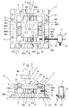
- Fig.l is a plan view showing one embodiemnt of a device for vibrating materials to be ground according to the invention
- Fig.2 is a cross sectional view thereof
- Figs.2-A and 2-B are side views, partially in section, shwing relation between the base of the actuator and the table
- Fig.3 is an explanatory view showing one example of a control system of the present device
- Fig.4 is an explanatory view showing a practising condition and a control system
- Fig.5 is an explanatory view showing a practising example and a control system
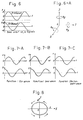
- Fig.6 is waves showing examples of controlling vibration of the table of the invention
- Fig.6-A is an explanatory view showing vibrations available in the invention
- FIG. 7-A, 7-B and 7-C are signal waves when the function generator is used;
- Fig.8 is a line showing a track of the table obtained by Fig.7-A;
- Fig.9 is a plan view showing the other embodiment of the invention;
- Fig.10 is a cross sectional view thereof;
- Fig.11 is a graph showing a load changing in comparison with a foregoing method when the present invention is used to coring of a fine ceramics;
- Fig.12 is a graph showing relation between a ground area and a load when a grinding width is changed; and
- Fig.13 is a graph showing grinding efficiency when the present invention is used to finishing of the surface of the fine ceramics.
- the device for vibrating materials to be ground of the invention is as a whole composed of a main body T and an electric controller C as seen in Fig.3.
- Figs.l and 2 show the main body T
- 1 is a base which is made of a material strong in mechanical strength such as a steel.
- the base 1 is shaped in box having an opened upper surface, composed of a bottom 10 and a peripheral wall 11.
- a seat 105 is defined where the base 1 is detachablly supported on the desired processing machine table 2 by securing holes 106, securing grooves 107, bolts and clampers.
- "Processing machine table” includes all of tables which, are stateonary, reciprocating or rotatable to be installed in the processing machine such as the grinder table, NC - table or the machining center table.
- the 3 designates a table which supports and fixes a work W which i, independent of the base 1.
- the work W is fixed on the table 3 by known holding instrument 30 as a vise, magnet chuck or vacuum chuck.
- Anti-water covers 16 are stretched over between the periphery of the table 3 and the peripheral wall 11 of the base 1 for avoiding a processing liquid, not obstructing vibration of the table 3, and the cover 16 is made of a flexible material as rubber or plastic.
- the table 3 is positioned centrally of the base 1, and each of X-, Y- and Z-directions is supported by the base 1 by means of a plurality of groups of piezoelectric actuators 401 to 412.
- the actuators are twelve in this embodiment, and as is seen in Fig.1, with respect to the actuators 401 to 404 in the X-direction, one group comprises two actuators which are opposite equidistantly between left and right inner faces of the peripheral wall 11 and the table 3.
- the actuators 405 to 408 in the Y-direction each comprise two with equidistant space between upper and lower inner faces of the peripheral wall 11 (in Fig.l) and the table 3.
- the actuators 409 to 412 in the Z-direction comprise each four disposed equidistantly between the bottom 10 and the lower surface of the table 3.
- the actuators 401 to 412 are strong in giving vibration and excellent in the mechanical strength. Suitable one is such as having a property being able to vibrate at the non-resonating point.
- a laminated piezoelectric element is employed.
- the laminated piezoelectric element is shown with the reference numeral 40 in Figs.2-A and 2-B, and is thin as, e.g., not more than 0.1 mm, and is laminated with a plurality of piezoelectric ceramics 41 shaped in wafer polarized in thickness such that the polarization directions are opposite per each of layers.
- This kind of element creats a large difference with small ignition voltage, and is excellent in displacing responsibility and temperature stability.
- 42 is an insulating cover
- 43 is a positive lead
- 44 is a negative lead.
- each of the actuators 401 to 412 at least one end in an expansion direction should be necessarily fixed to the base 1, while the other end be always closed to the table 3 not to separate at vibration of the table.
- the actuators 401 to 412 are connected to the peripheral wall 11 or the bottom 10 at one ends in the expansion direction via a strong adhesive 21 such as epoxy group, and the base 1 is connected to the table 3 via tension springs 5 making pairs with the actuators. By the force of the spring 5, the end of the actuator is connected to the outer face of the table.
- the laminated piezoelectric element 40 composing the actuator is cylindrical with a penetrating hole 45e, and is connected to the base 1 at its end the adhesive 21.
- the table 3 is formed with a female hole 300
- the base 1 is formed with a passage 100 communicating with an enlarged hole 101.
- the penetrating hole 45 is of course protected with an insulating material.
- a bolt 46 runs through the passage 100-and the penetrating hole 45 from the enlarged hole 101, and the bolt 46 is inserted into the female hole 300 at its screwed end portion 460.
- a spring 48 is interposed between a head 461 within the enlarged hole 101, and a shim 47 positioned at the bottom of the hole, by which the bolt 46 is biased to the left, and an end of the element 40 is pressed to the outer face 301 of the table 3 so as to effect a pressure.
- This system has an advantage that the extent of pre-pressure may be easily changed by controlling the screwing amount of the bolt 46.
- a piezostack of Langevin type may be employed. This type is as seen.inFig.2-B that the piezoelectric ceramics 41 sliced in wafer are laminated, and the bolt 46 passes through the hole 45 formed in a center thereof, so that an upper and a lower ends are fixed at a determined pre-pressure.
- a spring is omitted, and the screw portion 460 extending from one end is screwed into the female hole 300 of the table 3, and the bolt head 461 extending from the other end is fitted in a hole 102 formed in the base 1 and is secured to the bolt head with an adhesive 21.
- the table 3 is displaced at this time by balancing between the elongation of the piezoelectric ceramics and the elastic deformation of the center bolt 46a.
- the control device C not only turns ON and OFF actions of the piezoelectric actuators 401 to 412, but also selects them in response to the processing kinds, manners, conditions and so on, and ignites the selected one with the same or different voltage simultaneously in time or at time lag.
- the control device C is, as shown in Fig.3, provided with a power amplifier 6 of high speed type repesented by at least bypolar electric source, an electric device controller 7 and a computer 8.
- the electric device controller 7 is provided with a connector 70 for the piezoelectric actuators 401 to 412, a connector 71 for the power amplifier 6, and switching circuits.
- Fig.3 shows the switching circuits as transistors Tr1 to Tr12 of one step for simplification.
- terminals of the connectors of Fig.3, 1 corresponds to the piezoelectric actuator 401, 2 to the piezoelectric actuator 402, and the last 12 to the piezoelectric actuator 412.
- a connector 72 is disposed at the base of the switching circuit, the connector 72 being for inputting the control signal, to which D/A convertor 81 of the computer 8 is connected (see Figs.4 and 5).
- the positive poles (or negative poles) are rendered common, and the common leads and leads (12) of other poles are lead outside of the base 1 via the rubber bush 50 and connected to the connector 70 as shown in Figs.1 and 2.
- a microcomputer or a personal computer is employed for signal-controlling an output voltage issued from the power amplifier 6 by the program provided in the main body 80 including CPU, memories and others. That is, the output voltage is assigned to all of the piezoelectric actuators 401 to 412 or especial ones, and an extent of the voltage is controlled.
- a function generator 9 is connected to the input side of the power amplifier 6.
- the function generator 9 controls output frequency of the power amplifier 6, and produces various variations as sinusoidal waves, saw waves or short waves. If the function generator is used jointly, it is possible to combine control of the frequency by said joint use, rough control of the frequency and the voltage level by the computer 8, so that the flexibility of the control signal may be increased for the actuators 401 to 412.
- vibration displacement detectors 31 for example, displacement gauges of eddy current type are incorporated respectively, as shown inFigs.1 and 2, between the base 1 and the table 3, especially with respect to X- and Y-directions, between two piezoelectric actuators, and with respect to Z-direction, at the center of four piezoelectric actuators.
- the vibration displacement detector 31 is connected to the input 82 of the computer 8 via the amplifier 32 as shown in Figs.4 and 5.
- vibration displacement between the table 3 and the end of the actuator at the base, and a response frequency are measured by in-process, and informations thereof are calcurated by the computer 8, and ignition voltage to the actuators 401 to 412 is amended.
- ignition voltage to the actuators 401 to 412 is amended.
- a grinding resistance (load) detector 12 As a load cell for other feed back element, as shown in Fig.4 and 5, between the lower surface of the base 1 and the processing machine table 2.
- This grinding resistance detector 12 is connected at its output to an input 82 of the computer 8 via the amplifier 13, so that it is possible to select the optimum piezoelectric actuator and control the ignition voltage in response to the resistance (load) given to the work W during processing.
- Fig.5 shows the proper control for applying the present device to a complex machining, for example, discharge machining or electrolytic machining.
- the grindstone 4 and the main shaft 4a are isolated electrically by an isolating material 33 and the work W and a securing means 30 are also the same with an isolating material 34.
- Wirings of feeder brushes 14a, 14b to the grindstone 4 and the work W are connected to an output branched from the power amplifier 6 via a polar changing switch 15.
- F igs.9 and 10 show another embodiment of the invention, which shows a plain type for giving'vibration in Z-direction only where the base 1 is disc-shaped and formed with a seat 105 at its lower outside for the process machining table, which is formed with fixing holes 106 and fixing grooves 107.
- Table 3 is positioned above the base 1 and is capped with a plate 3a which may be omitted.
- the three cylindrical piezoelectric actuators 409 to 411 are disposed equidistantly and are secured at the lower surfaces on the upper surface of the base 1 with the adhesive 21.
- the upper surface of the table 3 is contacted to the lower surface of the table 3, and the pre-pressure is given to the piezoelectric actuators 409 to 411 by the system of the bolt 46 and the spring 48 shown in Fig.2-A.
- a water-proof cover 16 encircles the upper and outer periphery of the base 1, the lower and outer periphery of the table 3 and a space therebetween, and is sealed with O-rings 160, 160 at the both ends of the cover 16 so as to protect the piezoelectric actuators from the processing liquid,
- a vibrating displacement detector 31 is incorporated at the center of the base 1, and a backing cover 35 is attached to the bottom of the base 1.
- a control device to the body T shown in Figs, and 10 is omitted in depiction and description, since it is the same as those shown in Figs.3 to 5.
- the base 1 and the table are rectangular in plan, and of course may be circular in plan.
- Number of the piezoelectric actuators is not limited to twelve. The same may be applied to the embodiment of Figs.9 and 10, and the piezoelectric actuators may be four or five.
- the device T is mounted on the desired process machining table 2 or the grinding resistance detector 12, and is secured by means of the fixing holes 106 and the fixing grooves 107 of the seat 105.
- the power amplifier 6 When the power amplifier 6 is not actuated, the voltage is not ignited to the piezoelectric actuators 401 to 412, and so the table 3 holding the work W is supported statically on the base 1 by means of the actuators 401 to 412 and functions as an ordinary work table. Therefore, the machining process is carried out by pressing the rotating grindstone 4 to the work W at predetermined load, and moving the machining table 2 or moving the grindstone 4 for giving a desired feed.
- the driving voltage is ignited to the actuators 401 to 412 via the electric device 7, and the piezoelectric elements 4.01 to 412 sink. Since said sinking is transmitted to the table 3 mechanically, the table 3 is vibrated, and the work W is also moved accordingly.
- the control signal is input to the electric device controller 7 from the computer 8.
- the amplitude and the direction of the vibration are controlled. That is, the amplitude of the vibration is realized by sending the control signal from the computer 8 with respect to the determined output of the power amplifier 6, and the ignition voltage to the actuators 401 to 412 changes.
- the vibrating direction may be determined at disposal by sending a signal as to which actuators 401 to 412 the voltage is ignited to from the computer 8.
- the vibration is provided in a normal grinding force, and if it is given to the actuators 405 to 408 for Y-axial direction, the vibration is provided in a tangential grinding force, and if it is given to the actuators 401 to 404 for X-axial direction, the vibration is provided in lateral direction. Further, if the ignition is concurrenty given to the actuators in different directions, for example, in Z-and X- directions, complicated vibrations compounded with more than two directions are provided.
- a plurality of piezoelectric actuators form one group in X -, Y-, and Z-directions, respectively. Therefore, if the actuators composing respective groups are ignited at the same time, translational vibrations are effected on the table 3. If these actuators are ignited successively at time lag, such a vibration pattern including rotational vibration is formed.
- the above vibrations may be controlled by the control signal issued from the computer 8.
- the vibration mode may be made variable between vertical vibration in thickness and area vibration.
- the relations between the voltage polarities, the displacing directions and the rotating directions to be ignited to the actuators 401 to 412 are as follows.
- the ignition voltage is as follows.
- the output signal is fixed at DC level, and if the signal of the computer 8 is made as shown in Fig.6, the table 3 draws the oval track within the XY plain. If the signal frequency and the wave of the function generator 9 are varied, complicated waves as shown in Figs.7-A to 7-C may be easily obtained. Therefore, the table 3 is caused to draw an oval track as Fig.8 by the complicated wave vibrating therearound.
- the flexible vibration is possible in response to grinding resistance by the feed back system.
- the computer 8 is programmed such that the vibrating amplitude is increased when the grinding resistance becomes larger, amount of non-grinding which is generated by escaping from the grindstone or the work due to the grinding resistance, may be reduced.
- the work can be chamfered at its edge by detecting changings in the grinding resistance at starting or ending of the cutting, and it is possible to avoid pitching of the hard and brittle material, which is easily caused.
- the changing of the grinding resistance during processing is more effective in a surface finish-grinding process where the area being ground changes such as a cup typed grinder, than a straight typed grinder.
- the power amplifier 6 as the driving source of the table 3 may be used as a discharging - electrolyting source. So, facility cost and processing cost are saved without requiring addition of any special electric source unit. Besides, it is possible to synchronize the displace of the table 3, the effects of discharging electrolyting between the grindstone and the work, or synergestic effects which could not be realized ordinarily.
- a discharging grinding and an electrolyting grinding are selected in dependence upon processing liquids supplied from a coolant nozzle 17.
- the polarity of the voltage to be ignited to between the grindstone and the work can be easily switched by the polarity changing switch 15, and the automatic switch by an order from the computer 8 is possible. Therefore, the work can be processed at high efficiency by the work side (+) and the grindstone side (-), and the grindstone can be dressed at high efficiency by the work side (-) and the grindstone side (+). If the grinding resistance is not reduced in spite of the complicated control of the table 3, a sequence which carries out the automatic dressing by the in-process not intermitting the process, can be composed by pre-programming for automatically switching the p ola - rity of the ignition voltage between the grindstone and the work.
- the piezoelectric actuators were the cylindrical laminated type of 18.4 mm ⁇ in an outer diameter, 7 mm ⁇ in an inner diameter and 18 mm in height, having 170 sheets of laminated PZT ceramics of 100 um in thickness.
- the vibrations of 16 ⁇ m were made with the ignition voltage of 150 V, having the compression force of 6000 kg/cm , the tension strength of 100 kg/cm 2 and the self- resonant frequency of 67 KHz.
- the Young' rate at ignition of 150 V was 5.6 x 10 10 N/m 2 .
- the stold force of 800 kgf was generated.
- the twelve piezoelectric actuators are positioned between the base and the table as seen in Figs. and 2, and are connected to the table at its end with the epoxy resin and to the table at its end with the practice as shown in Fig.2-A.
- the table is 100 mm in width and length and 20 mm in thickness.
- the total hight of the device is 80 mm.
- the grinding machine was a portal machining center, on the table of which the device was placed via the load cell.
- the grindstone was a cast iron fiber bond diamond (core drill type, ⁇ 10 mm, #60/80).
- the table vibrating electric power was a high speed power amplifier function synthesyzer, and the signal of the load cell was incorporated into the personal computer.
- the vibration was given in the Z-direction by the most simplified practice of driving simultaneously the four piezoelectric actuators.
- the peripheral speed was 200 m/min, the feed was 1 mm/min.
- the conventional normal practice which did not give the vibration to the table was performed under the same conditions, and the results are shown in Fig. 11.
- the load in the vertical direction of the conventional practise was 100 kgf, but according to the present invention, the ignition voltage was 150 V, the frequency was 200 Hz, and the vibration was 15, ⁇ mp-p, and in the sinusoidal wave, the load was 30 kgf, that is, reduced to about 1/3 of the conventional practice, because the breaking of the work was accelerated by the strong vibration of the piezoelectric actuators.
- the relationship between the cutting area and the vertical load was studied at the feeding rate of 2 m/min by changing the cutting width of the coring, and the results are shown in Fig.12 where 13.7 mm of the cutting area was 1/4 face cutting, 27.4 mm 2 was a half face cutting and 54.8 mmz was an overall cutting.
- the load of the overall cutting was more than 110 kgf, but in the vibration coring of the invention, the load in each of the ground faces was controlled 1/2 to 1/3 of the conventional practice.
- the feed speed and the load at coring was studied.
- the feed speed was 2 mm/min to the maximum and the work was broken at 4 mm/min.
- the coring could be performed stably at 45 kgf, in spite of the high speed of 10 mm/min.
- the durability of the table was investigated.
- the table was vibrated without causing any problems, in spite of 250 kgf of the load in the vertical direction and the continuous vibration for 8 hours at 2000 Hz.
- the finish processing was made to the same work by the pressure giving practice.
- the grindstone was a cast iron fiber bond grindstone (cut grindstone,f200, grain size #4000), the peripheral speed of 569 m/min and the same vibrating condition as the above said coring. The results thereof are shown in Fig.13.
- the grinding efficiency exceeding more than twice of the conventional practice could be realized, because the brittle fracture of the ceramics rewe accelerated by the impact of the vibration and the increasing effect of the pressure.
- the device for vibrating the work to be processed is applicable to the brittle materials such as fine ceramics, glasses, carbide alloys, and further to the whole processes using the grinding_powders to the ferrite, silicon and so on.
- the processes using th.e grinding powders include surface grinding, cylindrical grinding, internal grinding, lapping grinding, free grinding, groove grinding, thread grinding, and abrasive cut-off.
Landscapes
- Engineering & Computer Science (AREA)
- Mechanical Engineering (AREA)
- Chemical & Material Sciences (AREA)
- Ceramic Engineering (AREA)
- Inorganic Chemistry (AREA)
- Grinding And Polishing Of Tertiary Curved Surfaces And Surfaces With Complex Shapes (AREA)
- Constituent Portions Of Griding Lathes, Driving, Sensing And Control (AREA)
Applications Claiming Priority (2)
| Application Number | Priority Date | Filing Date | Title |
|---|---|---|---|
| JP155340/87 | 1987-06-24 | ||
| JP62155340A JPH0722876B2 (ja) | 1987-06-24 | 1987-06-24 | 研削用ワークテーブル装置 |
Publications (3)
| Publication Number | Publication Date |
|---|---|
| EP0323518A1 true EP0323518A1 (de) | 1989-07-12 |
| EP0323518A4 EP0323518A4 (en) | 1990-12-05 |
| EP0323518B1 EP0323518B1 (de) | 1993-03-17 |
Family
ID=15603750
Family Applications (1)
| Application Number | Title | Priority Date | Filing Date |
|---|---|---|---|
| EP88906026A Expired - Lifetime EP0323518B1 (de) | 1987-06-24 | 1988-06-23 | Vorrichtung, um ein zu schleifendes werkstück ins schwingen zu bringen |
Country Status (6)
| Country | Link |
|---|---|
| US (1) | US5165205A (de) |
| EP (1) | EP0323518B1 (de) |
| JP (1) | JPH0722876B2 (de) |
| KR (1) | KR930002184B1 (de) |
| DE (1) | DE3879448T2 (de) |
| WO (1) | WO1988010174A1 (de) |
Cited By (5)
| Publication number | Priority date | Publication date | Assignee | Title |
|---|---|---|---|---|
| WO1993015877A1 (de) * | 1992-02-06 | 1993-08-19 | Ppv-Verwaltungs-Ag | Vorrichtung zum schleifen von werkstücken |
| WO2012084779A1 (de) | 2010-12-21 | 2012-06-28 | Ev Group Gmbh | Vorrichtung mit zwei schwingungskomponenten zum spanenden bearbeiten eines werkstücks |
| WO2012167288A1 (de) | 2011-05-18 | 2012-12-13 | Technische Universität Wien | Schwingvorrichtung mit werkstückaufnahme und ausgleichsmasse |
| CN103042435A (zh) * | 2012-11-09 | 2013-04-17 | 浙江工业大学 | 拼接淬硬模具钢高频微幅振动铣削测试方法 |
| WO2013142890A1 (de) | 2012-03-28 | 2013-10-03 | Technische Universität Wien | Vorrichtung, maschine und verfahren zur mechanischen bearbeitung eines werkstücks |
Families Citing this family (25)
| Publication number | Priority date | Publication date | Assignee | Title |
|---|---|---|---|---|
| US5245790A (en) * | 1992-02-14 | 1993-09-21 | Lsi Logic Corporation | Ultrasonic energy enhanced chemi-mechanical polishing of silicon wafers |
| CH690865A5 (de) * | 1996-05-09 | 2001-02-15 | Kk Holding Ag | Kraft- und Momentmessanordnung. |
| DE19928950A1 (de) * | 1999-06-24 | 2000-12-07 | Wacker Siltronic Halbleitermat | Verfahren zum Schleifen der Oberfläche eines Werkstücks |
| KR20020030996A (ko) * | 2000-10-20 | 2002-04-26 | 박경 | 판유리 변형 면취기의 탄성 테이블 |
| JP4721574B2 (ja) * | 2001-08-29 | 2011-07-13 | 株式会社ディスコ | 研削装置の原点位置設定機構 |
| US6808304B2 (en) * | 2002-08-27 | 2004-10-26 | Dade Behring Inc. | Method for mixing liquid samples using a linear oscillation stroke |
| JP4179053B2 (ja) * | 2003-05-27 | 2008-11-12 | 松下電工株式会社 | マッサージ機 |
| TWI236371B (en) | 2003-05-27 | 2005-07-21 | Matsushita Electric Works Ltd | Massaging device |
| JP2006062017A (ja) * | 2004-08-26 | 2006-03-09 | Honda Motor Co Ltd | 加振装置 |
| DE102005027727B4 (de) * | 2005-06-16 | 2009-04-02 | Hochschule Magdeburg-Stendal (Fh) | Antriebseinrichtung zur Finishbearbeitung |
| DE102005038108A1 (de) * | 2005-08-11 | 2007-02-15 | Multi Orbital Systems Gmbh | Vorrichtung und Verfahren zum Bearbeiten von Oberflächen |
| US7508116B2 (en) | 2005-09-07 | 2009-03-24 | Panasonic Corporation | Method and apparatus for vibration machining with two independent axes |
| KR100783525B1 (ko) | 2006-07-19 | 2007-12-11 | 건국대학교 산학협력단 | 평면 디버링장치 |
| ES2547559T3 (es) | 2009-03-06 | 2015-10-07 | Mitsubishi Electric Corporation | Sistema de cocción por calentamiento por inducción |
| DE102009017248A1 (de) * | 2009-04-09 | 2010-10-21 | Azarhoushang, Bahman | Ultraschalleinheit für die Materialbearbeitung |
| JP5352331B2 (ja) * | 2009-04-15 | 2013-11-27 | ダイトエレクトロン株式会社 | ウェーハの面取り加工方法 |
| TWM411311U (en) * | 2011-04-07 | 2011-09-11 | Chuan Liang Ind Co Ltd | Operating table ultrasonic device for tooling machine |
| DE102013110728B4 (de) * | 2013-09-27 | 2021-08-19 | Ev Group E. Thallner Gmbh | System und Verfahren zum spanenden Bearbeiten eines Werkstücks |
| CN103769958B (zh) * | 2014-01-27 | 2017-01-04 | 河北工业大学 | 一种超声振动平台 |
| CN103990998B (zh) * | 2014-05-20 | 2017-01-25 | 广东工业大学 | 基于应力刚化原理的刚度频率可调二维微动平台 |
| DE102014119166B4 (de) | 2014-12-19 | 2018-06-07 | SMS Maschinenbau GmbH | Schleifmaschine |
| JP6814579B2 (ja) * | 2016-09-20 | 2021-01-20 | 株式会社ディスコ | 研削ホイール及び研削装置 |
| CN108620963A (zh) * | 2017-03-26 | 2018-10-09 | 许昌义 | 气动式三维力振动研磨机 |
| US10564553B2 (en) * | 2017-09-26 | 2020-02-18 | Guangdong University Of Technology | Large load-bearing guide mechanism and multi-DOF large-stroke high-precision motion platform system |
| JP7020694B2 (ja) * | 2019-08-30 | 2022-02-16 | 株式会社アクトラス | 攪拌方法 |
Family Cites Families (8)
| Publication number | Priority date | Publication date | Assignee | Title |
|---|---|---|---|---|
| US2439219A (en) * | 1944-06-09 | 1948-04-06 | John C O'connor | Apparatus for transmitting intense vibrations for performing work |
| US2939250A (en) * | 1957-01-31 | 1960-06-07 | Micromatic Hone Corp | Resonant honing |
| FR1492788A (fr) * | 1965-07-20 | 1967-08-25 | Soudure Elec Languepin | Procédé et dispositif d'usinage par érosion mécanique |
| SU740483A1 (ru) * | 1977-12-27 | 1980-06-15 | Предприятие П/Я Р-6930 | Вибромашина дл вибрационной обработки деталей |
| SU797750A1 (ru) * | 1978-04-06 | 1981-01-23 | Государственный Союзный Заводпо Механической И Химическойочистке Котлоагрегатов | Способ перемешивани веществ иуСТРОйСТВО дл ЕгО ОСущЕСТВлЕНи |
| JPS6176261A (ja) * | 1984-09-25 | 1986-04-18 | Hitachi Ltd | 超音波加工機 |
| JPS61219549A (ja) * | 1985-03-25 | 1986-09-29 | Agency Of Ind Science & Technol | 微動装置 |
| JPH06171950A (ja) * | 1992-12-02 | 1994-06-21 | Shin Etsu Chem Co Ltd | ランタンマンガナイト粉末の製造方法 |
-
1987
- 1987-06-24 JP JP62155340A patent/JPH0722876B2/ja not_active Expired - Lifetime
-
1988
- 1988-06-23 EP EP88906026A patent/EP0323518B1/de not_active Expired - Lifetime
- 1988-06-23 WO PCT/JP1988/000620 patent/WO1988010174A1/ja active IP Right Grant
- 1988-06-23 KR KR1019880701316A patent/KR930002184B1/ko not_active IP Right Cessation
- 1988-06-23 US US07/269,145 patent/US5165205A/en not_active Expired - Fee Related
- 1988-06-23 DE DE8888906026T patent/DE3879448T2/de not_active Expired - Fee Related
Non-Patent Citations (2)
| Title |
|---|
| No further relevant documents have been disclosed. * |
| See also references of WO8810174A1 * |
Cited By (13)
| Publication number | Priority date | Publication date | Assignee | Title |
|---|---|---|---|---|
| US5540614A (en) * | 1992-02-06 | 1996-07-30 | Ppv - Verwaltungs-Ag | Apparatus for grinding workpieces |
| WO1993015877A1 (de) * | 1992-02-06 | 1993-08-19 | Ppv-Verwaltungs-Ag | Vorrichtung zum schleifen von werkstücken |
| KR101487637B1 (ko) * | 2010-12-21 | 2015-01-29 | 에베 그룹 게엠베하 | 공작물을 가공하기 위해 두 개의 진동 요소를 가지는 시스템 |
| WO2012084779A1 (de) | 2010-12-21 | 2012-06-28 | Ev Group Gmbh | Vorrichtung mit zwei schwingungskomponenten zum spanenden bearbeiten eines werkstücks |
| US9061388B2 (en) | 2010-12-21 | 2015-06-23 | Ev Group Gmbh | System having two oscillation components for machining a workpiece |
| WO2012167288A1 (de) | 2011-05-18 | 2012-12-13 | Technische Universität Wien | Schwingvorrichtung mit werkstückaufnahme und ausgleichsmasse |
| AT511551A1 (de) * | 2011-05-18 | 2012-12-15 | Univ Wien Tech | Vorrichtung und verfahren zur mechanischen bearbeitung eines werkstücks |
| US9346139B2 (en) | 2011-05-18 | 2016-05-24 | Technische Universität Wien | Vibrating device with workpiece receiving portion and compensating mass |
| AT511551B1 (de) * | 2011-05-18 | 2013-10-15 | Univ Wien Tech | Vorrichtung und verfahren zur mechanischen bearbeitung eines werkstücks |
| WO2013142890A1 (de) | 2012-03-28 | 2013-10-03 | Technische Universität Wien | Vorrichtung, maschine und verfahren zur mechanischen bearbeitung eines werkstücks |
| AT513094B1 (de) * | 2012-03-28 | 2015-01-15 | Tech Universität Wien | Vorrichtung, insbesondere Spanwerkzeug |
| AT513094A1 (de) * | 2012-03-28 | 2014-01-15 | Univ Wien Tech | Vorrichtung, insbesondere Spanwerkzeug |
| CN103042435A (zh) * | 2012-11-09 | 2013-04-17 | 浙江工业大学 | 拼接淬硬模具钢高频微幅振动铣削测试方法 |
Also Published As
| Publication number | Publication date |
|---|---|
| EP0323518A4 (en) | 1990-12-05 |
| DE3879448D1 (de) | 1993-04-22 |
| WO1988010174A1 (en) | 1988-12-29 |
| JPH0722876B2 (ja) | 1995-03-15 |
| EP0323518B1 (de) | 1993-03-17 |
| DE3879448T2 (de) | 1993-07-29 |
| JPS642852A (en) | 1989-01-06 |
| US5165205A (en) | 1992-11-24 |
| KR890700426A (ko) | 1989-04-24 |
| KR930002184B1 (ko) | 1993-03-27 |
Similar Documents
| Publication | Publication Date | Title |
|---|---|---|
| EP0323518B1 (de) | Vorrichtung, um ein zu schleifendes werkstück ins schwingen zu bringen | |
| JPH012852A (ja) | 研削用ワークテーブル装置 | |
| CN108972302B (zh) | 一种非谐振式振动辅助抛光装置及方法 | |
| CN101380721A (zh) | 一种用于大型结构件磨削的二维超声振动辅助磨削装置 | |
| CN205111610U (zh) | 大尺寸径向超声辅助端面磨削磨盘 | |
| GB2134019A (en) | Abrasively contour-finishing a workpiece | |
| JP2007125867A (ja) | 円盤状ブレード及び切断装置 | |
| CN105058254A (zh) | 一种大尺寸径向超声辅助端面磨削磨盘 | |
| CN205111466U (zh) | 一种大尺寸轴向超声辅助端面磨削磨盘 | |
| JP2011183510A (ja) | 超音波振動援用研削法及びその装置 | |
| KR100417643B1 (ko) | 초음파 진동공구를 이용한 금형 다듬질 자동화장치 | |
| CN105150034B (zh) | 一种实现端面超声辅助研磨和抛光的磨头 | |
| JPH0730137Y2 (ja) | 圧電素子を利用した振動テーブル | |
| JP2007283418A (ja) | 切削工具 | |
| Wu et al. | A new centerless grinding technique without employing a regulating wheel | |
| CN105150033A (zh) | 一种大尺寸轴向超声辅助端面磨削磨盘 | |
| JP2000167715A (ja) | ホーニング方法、研削方法、及びこれらの方法を実施する装置 | |
| JP2004351605A (ja) | 超音波振動テーブル | |
| JPH03234451A (ja) | ねじり振動を利用した研摩法 | |
| JPH03161255A (ja) | アタッチメント式超音波加工によるワークの穴あけ内面のラッピング研磨方法及びその装置 | |
| JPS6362659A (ja) | 複合振動砥石による精密仕上加工方法 | |
| CN209970283U (zh) | 一种微细超声加工系统 | |
| JPH07164288A (ja) | 超音波振動研削方法、超音波振動研削工具、及び超音波振動研削加工装置 | |
| WO2003095144A1 (fr) | Dispositif de rodage et procede de travail de rodage | |
| DE102004061222B3 (de) | Schleifmaschine |
Legal Events
| Date | Code | Title | Description |
|---|---|---|---|
| PUAI | Public reference made under article 153(3) epc to a published international application that has entered the european phase |
Free format text: ORIGINAL CODE: 0009012 |
|
| 17P | Request for examination filed |
Effective date: 19890410 |
|
| AK | Designated contracting states |
Kind code of ref document: A1 Designated state(s): CH DE FR GB LI |
|
| A4 | Supplementary search report drawn up and despatched |
Effective date: 19901018 |
|
| AK | Designated contracting states |
Kind code of ref document: A4 Designated state(s): CH DE FR GB LI |
|
| 17Q | First examination report despatched |
Effective date: 19920617 |
|
| GRAA | (expected) grant |
Free format text: ORIGINAL CODE: 0009210 |
|
| AK | Designated contracting states |
Kind code of ref document: B1 Designated state(s): CH DE FR GB LI |
|
| REF | Corresponds to: |
Ref document number: 3879448 Country of ref document: DE Date of ref document: 19930422 |
|
| ET | Fr: translation filed | ||
| PLBE | No opposition filed within time limit |
Free format text: ORIGINAL CODE: 0009261 |
|
| STAA | Information on the status of an ep patent application or granted ep patent |
Free format text: STATUS: NO OPPOSITION FILED WITHIN TIME LIMIT |
|
| 26N | No opposition filed | ||
| PGFP | Annual fee paid to national office [announced via postgrant information from national office to epo] |
Ref country code: CH Payment date: 19940531 Year of fee payment: 7 |
|
| PGFP | Annual fee paid to national office [announced via postgrant information from national office to epo] |
Ref country code: GB Payment date: 19940615 Year of fee payment: 7 |
|
| PGFP | Annual fee paid to national office [announced via postgrant information from national office to epo] |
Ref country code: FR Payment date: 19940630 Year of fee payment: 7 |
|
| PGFP | Annual fee paid to national office [announced via postgrant information from national office to epo] |
Ref country code: DE Payment date: 19940824 Year of fee payment: 7 |
|
| PG25 | Lapsed in a contracting state [announced via postgrant information from national office to epo] |
Ref country code: GB Effective date: 19950623 |
|
| PG25 | Lapsed in a contracting state [announced via postgrant information from national office to epo] |
Ref country code: LI Effective date: 19950630 Ref country code: CH Effective date: 19950630 |
|
| GBPC | Gb: european patent ceased through non-payment of renewal fee |
Effective date: 19950623 |
|
| PG25 | Lapsed in a contracting state [announced via postgrant information from national office to epo] |
Ref country code: FR Effective date: 19960229 |
|
| REG | Reference to a national code |
Ref country code: CH Ref legal event code: PL |
|
| PG25 | Lapsed in a contracting state [announced via postgrant information from national office to epo] |
Ref country code: DE Effective date: 19960301 |
|
| REG | Reference to a national code |
Ref country code: FR Ref legal event code: ST |