EP0322471B1 - Einrichtung zum Messen eines Fadens - Google Patents
Einrichtung zum Messen eines Fadens Download PDFInfo
- Publication number
- EP0322471B1 EP0322471B1 EP87119213A EP87119213A EP0322471B1 EP 0322471 B1 EP0322471 B1 EP 0322471B1 EP 87119213 A EP87119213 A EP 87119213A EP 87119213 A EP87119213 A EP 87119213A EP 0322471 B1 EP0322471 B1 EP 0322471B1
- Authority
- EP
- European Patent Office
- Prior art keywords
- measuring
- thread
- housing
- guide element
- frame
- Prior art date
- Legal status (The legal status is an assumption and is not a legal conclusion. Google has not performed a legal analysis and makes no representation as to the accuracy of the status listed.)
- Expired - Lifetime
Links
- 238000004140 cleaning Methods 0.000 claims abstract description 9
- 239000003990 capacitor Substances 0.000 claims description 4
- 238000005452 bending Methods 0.000 claims description 3
- 230000005684 electric field Effects 0.000 claims description 2
- 238000001746 injection moulding Methods 0.000 claims description 2
- 238000010276 construction Methods 0.000 claims 3
- 230000004075 alteration Effects 0.000 claims 1
- 238000005520 cutting process Methods 0.000 claims 1
- 238000000034 method Methods 0.000 claims 1
- 239000000428 dust Substances 0.000 abstract description 3
- 238000009825 accumulation Methods 0.000 abstract 1
- 238000011109 contamination Methods 0.000 abstract 1
- 238000005259 measurement Methods 0.000 description 2
- 239000000919 ceramic Substances 0.000 description 1
- 230000000694 effects Effects 0.000 description 1
- 238000012544 monitoring process Methods 0.000 description 1
- 238000004080 punching Methods 0.000 description 1
- 239000004753 textile Substances 0.000 description 1
Images
Classifications
-
- G—PHYSICS
- G01—MEASURING; TESTING
- G01B—MEASURING LENGTH, THICKNESS OR SIMILAR LINEAR DIMENSIONS; MEASURING ANGLES; MEASURING AREAS; MEASURING IRREGULARITIES OF SURFACES OR CONTOURS
- G01B11/00—Measuring arrangements characterised by the use of optical techniques
- G01B11/08—Measuring arrangements characterised by the use of optical techniques for measuring diameters
- G01B11/10—Measuring arrangements characterised by the use of optical techniques for measuring diameters of objects while moving
- G01B11/105—Measuring arrangements characterised by the use of optical techniques for measuring diameters of objects while moving using photoelectric detection means
-
- B—PERFORMING OPERATIONS; TRANSPORTING
- B65—CONVEYING; PACKING; STORING; HANDLING THIN OR FILAMENTARY MATERIAL
- B65H—HANDLING THIN OR FILAMENTARY MATERIAL, e.g. SHEETS, WEBS, CABLES
- B65H63/00—Warning or safety devices, e.g. automatic fault detectors, stop-motions ; Quality control of the package
- B65H63/06—Warning or safety devices, e.g. automatic fault detectors, stop-motions ; Quality control of the package responsive to presence of irregularities in running material, e.g. for severing the material at irregularities ; Control of the correct working of the yarn cleaner
- B65H63/062—Electronic slub detector
- B65H63/065—Electronic slub detector using photo-electric sensing means, i.e. the defect signal is a variation of light energy
-
- D—TEXTILES; PAPER
- D01—NATURAL OR MAN-MADE THREADS OR FIBRES; SPINNING
- D01H—SPINNING OR TWISTING
- D01H13/00—Other common constructional features, details or accessories
- D01H13/32—Counting, measuring, recording or registering devices
-
- B—PERFORMING OPERATIONS; TRANSPORTING
- B65—CONVEYING; PACKING; STORING; HANDLING THIN OR FILAMENTARY MATERIAL
- B65H—HANDLING THIN OR FILAMENTARY MATERIAL, e.g. SHEETS, WEBS, CABLES
- B65H2701/00—Handled material; Storage means
- B65H2701/30—Handled filamentary material
- B65H2701/31—Textiles threads or artificial strands of filaments
Definitions
- the invention relates to a device for measuring a thread, in which the degree of shading caused by the thread or its reflection on a photosensitive element or by the change in electrical capacitance, the thread in the electrical field of a capacitor on the capacitor causes at least one thread dimension and in which the thread can be inserted into a measuring slot of a measuring device.
- Document EP-A-0 227 861 discloses such a device.
- Such devices are used for example on textile machines for thread monitoring.
- the problem of pollution from flight, dust and thread parts arises.
- the invention has for its object to remove a generic device as far as possible from the effects of pollution and dust falsifying the measured values.
- this object is achieved in that a thread guide element is arranged at a distance from a frame or housing containing at least the measuring slot of the measuring device above and below the measuring slot and is connected to the frame or housing by a supporting structure such that between the measuring slot and thread guide elements there is a free passage for cleaning air.
- Such an arrangement of thread guide elements brings about a self-cleaning purpose, so that the arrangement is less dirty than conventional devices.
- the supporting structure of the thread guide element held at a distance from the measuring slot is part of the frame or housing enclosing or supporting the device.
- the support structure of the thread guide element advantageously consists of an outwardly projecting part formed by bending punching, injection molding or in the same way from the frame, a housing wall or the cover of the device.
- the housing 17 of an optoelectric device for measuring a thread 1, generally designated 18, has a measuring slot 19 through which the thread 1 is guided by means of thread guide elements 5, 6.
- the thread 1 runs in the direction of the arrow 21.
- a chamber is formed in the housing 17, in which a light source 2 is arranged, the light rays of which pass transversely through the measurement slot 19 and then strike measurement sensors (not shown). It is the Transducers around photosensitive elements, of which connection lines 37, 38 are visible in FIG. 2.
- a thread guiding element 5 or 6 is arranged at a distance from the housing 17 containing the light source 2, the measuring slot 19 and the measuring transducer above and below the measuring slot 19.
- the thread guide element 5 is connected by a support structure 33, the thread guide element 6 by a support structure 34 to the housing 17 such that between the measuring slot 19 and thread guide elements 5, 6 there is a free passage 35 or 36 in a width of 4 to 8 millimeters for cleaning air .
- the cleaning air originates, for example, from the running thread 1, which, at higher running speeds, can cause a draft and air swirls sufficient for cleaning purposes.
- the cleaning air can also be supplied from the environment or from special cleaning devices on a case-by-case basis or continuously, which, however, causes additional effort.
- the support structure 33 'of the thread guide element 5 held at a distance from the measuring slot 19 is part of the housing 17 enclosing the device 18, more precisely a housing cover 17'.
- the support structure 33 'of the thread guide element 5 consists of a formed by bending stamping from the cover 17', projecting outward part.
- Part 33 ' is bifurcated at its end so that it can enclose and hold the thread guide element 5 consisting of a notched sintered ceramic plate from two sides.
Landscapes
- Engineering & Computer Science (AREA)
- Textile Engineering (AREA)
- Physics & Mathematics (AREA)
- General Physics & Mathematics (AREA)
- Mechanical Engineering (AREA)
- Quality & Reliability (AREA)
- Treatment Of Fiber Materials (AREA)
- Length Measuring Devices By Optical Means (AREA)
- Investigating Materials By The Use Of Optical Means Adapted For Particular Applications (AREA)
- Length Measuring Devices With Unspecified Measuring Means (AREA)
- Measurement Of Length, Angles, Or The Like Using Electric Or Magnetic Means (AREA)
- Spinning Or Twisting Of Yarns (AREA)
Description
- Die Erfindung betrifft eine Einrichtung zum Messen eines Fadens, bei der aus dem Grad der Abschattung, die der Faden oder sein Spiegelbild an einem lichtempfindlichen Element verursacht oder aus der Änderung der elektrischen Kapazität, die der sich im elektrischen Feld eines Kondensators befindende Faden an dem Kondensator hervorruft, auf mindestens eine Fadendimension geschlossen wird und bei der der Faden in einen Meßschlitz einer Meßeinrichtung einlegbar ist. Das Dokument EP-A-0 227 861 offenbart eine solche Einrichtung.
- Derartige Einrichtungen werden beispielsweise an Textilmaschinen zur Fadenüberwachung eingesetzt. Dabei tritt das Problem der Verschmutzung durch Flug, Staub und Fadenteile auf.
- Der Erfindung liegt die Aufgabe zugrunde, eine gattungsgemäße Einrichtung den meßwertverfälschenden Einflüssen von Verschmutzung und Verstaubung soweit wie möglich zu entziehen.
- Gemäß der Erfindung wird diese Aufgabe dadurch gelöst, daß mit Abstand von einem mindestens den Meßschlitz der Meßeinrichtung enthaltenden Rahmen oder Gehäuse oberhalb und unterhalb des Meßschlitzes je ein Fadenführungselement angeordnet und durch eine Tragkonstruktion mit dem Rahmen oder Gehäuse derartig verbunden ist, daß zwischen Meßschlitz und Fadenführungselementen ein freier Durchgang für Reinigungsluft vorhanden ist.
- Eine derartige Anordnung von Fadenführungselementen bringt einen Selbstreinigungszweck zustande, so daß die Anordnung weniger verschmutzt als herkömmliche Vorrichtungen.
- In Weiterbildung der Erfindung ist die Tragkonstruktion des auf Abstand vom Meßschlitz gehaltenen Fadenführungselements ein Teil des die Einrichtung umschließenden oder tragenden Rahmens oder Gehäuses.
- Vorteilhaft besteht die Tragkonstruktion des Fadenführungselements aus einem durch Biegestanzen, Spritzgießen oder auf dergleichen Weise aus dem Rahmen, einer Gehäusewand oder dem Deckel der Einrichtung herausgebildeten, nach außen vorspringenden Teil.
- Ausführungsbeispiele der Erfindung sind in den Zeichnungen dargestellt. Anhand der Ausführungsbeispiele wird die Erfindung noch näher beschrieben und erläutert.
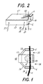
- Fig. 1
- zeigt die prinzipielle Anordnung der neuen Einrichtung.
- Fig. 2
- zeigt eine perspektivische Ansicht einer erfindungsgemäßen Einrichtung.
- Das Gehäuse 17 einer insgesamt mit 18 bezeichneten optoelektrischen Einrichtung zum Messen eines Fadens 1 besitzt einen Meßschlitz 19, durch den mittels Fadenführungselementen 5, 6 der Faden 1 hindurchgeführt ist. Der Faden 1 läuft in Richtung des Pfeils 21.
- In dem Gehäuse 17 ist eine Kammer ausgebildet, in der eine Lichtquelle 2 angeordnet ist, deren Lichtstrahlen quer durch den Meßschlitz 19 gehen und dann auf nicht dagestellte Meßwertaufnehmer auftreffen. Es handelt sich bei den Meßwertaufnehmern um lichtempfindliche Elemente, von denen in Fig. 2 Anschlußleitungen 37, 38 sichtbar sind.
- Bei der Ausbildung nach Fig. 1 ist mit Abstand von dem die Lichtquelle 2, den Meßschlitz 19 und die Meßwertaufnehmer enthaltenden Gehäuse 17 oberhalb und unterhalb des Meßschlitzes 19 je ein Fadenführungselement 5 beziehungsweise 6 angeordnet.
- Das Fadenführungselement 5 ist durch eine Tragkonstruktion 33, das Fadenführungselement 6 durch eine Tragkonstruktion 34 mit dem Gehäuse 17 derartig verbunden, daß zwischen Meßschlitz 19 und Fadenführungselementen 5, 6 ein freier Durchgang 35 beziehungsweise 36 in einer Breite vom 4 bis 8 Millimeter für Reinigungsluft vorhanden ist. Die Reinigungsluft entstammt beispielsweise dem laufenden Faden 1, der bei höheren Laufgeschwindigkeiten einen für Reinigungszwecke ausreichenden Luftzug und Luftwirbelungen verursachen kann. Die Reinigungsluft kann aber auch aus der Umgebung beziehungsweise aus besonderen Reinigungseinrichtungen von Fall zu Fall oder kontinuierlich zugeführt werden, was jedoch zusätzlichen Aufwand verursacht.
- Bei der Ausbildung nach Fig. 2 ist die Tragkonstruktion 33′ des auf Abstand vom Meßschlitz 19 gehaltenen Fadenführungselements 5 ein Teil des die Einrichtung 18 umschließenden Gehäuses 17, genauer gesagt eines Gehäusedeckels 17′.
- Die Tragkonstruktion 33′ des Fadenführungselements 5 besteht aus einem durch Biegestanzen aus dem Deckel 17′ herausgebildeten, nach außen vorspringenden Teil.
- Teil 33′ ist an seinem Ende gegabelt, so daß es das aus einem gekerbten Plättchen aus Sinterkeramik bestehende Fadenführungselement 5 von zwei Seiten her umschließen und halten kann.
Claims (3)
- Einrichtung zum Messen eines Fadens, bei der aus dem Grad der Abschattung, die der Faden (1) oder sein Spiegelbild an einem lichtempfindlichen Element verursacht, oder aus der Änderung der elektrischen Kapazität, die der sich im elektrischen Feld eines Kondensators befindende Faden an dem Kondensator hervorruft, auf mindestens eine Fadendimension geschlossen wird und bei der der Faden in einen Meßschlitz (19) einer Meßeinrichtung (18) einlegbar ist,
dadurch gekennzeichnet,
daß mit Abstand von einem mindestens den Meßschlitz (19) der Meßeinrichtung (18) enthaltenden Rahmen oder Gehäuse (17) oberhalb und unterhalb des Meßschlitzes (19) je ein Fadenführungselement (5, 6) angeordnet und durch eine Tragkonstruktion (33, 34) mit dem Rahmen oder Gehäuse (17) derartig verbunden ist, daß zwischen Meßschlitz (19) und Fadenführungselement (5, 6) ein freier Durchgang (35, 36) für Reinigungsluft vorhanden ist. - Einrichtung nach Anspruch 1, dadurch gekennzeichnet, daß die Tragkonstruktion (33′) des auf Abstand vom Meßschlitz (19) gehaltenen Fadenführungselements (5) ein Teil des die Einrichtung (18) umschließenden oder tragenden Rahmens oder Gehäuses (17) ist.
- Einrichtung nach Anspruch 1 oder 2, dadurch gekennzeichnet, daß die Tragkonstruktion (33′) des Fadenführungselements (5) aus einem durch Biegestanzen, Spritzgießen oder auf dergleichen Weise aus dem Rahmen, einer Gehäusewand oder dem Deckel (17) der Einrichtung (18) herausgebildeten, nach außen vorspringenden Teil besteht.
Priority Applications (5)
| Application Number | Priority Date | Filing Date | Title |
|---|---|---|---|
| DE8787119213T DE3772577D1 (de) | 1987-12-24 | 1987-12-24 | Einrichtung zum messen eines fadens. |
| EP87119213A EP0322471B1 (de) | 1987-12-24 | 1987-12-24 | Einrichtung zum Messen eines Fadens |
| AT87119213T ATE66736T1 (de) | 1987-12-24 | 1987-12-24 | Einrichtung zum messen eines fadens. |
| US07/288,486 US4970402A (en) | 1987-12-24 | 1988-12-22 | Apparatus for sensing characteristics of a traveling yarn with yarn guiding means |
| JP63323818A JPH01280210A (ja) | 1987-12-24 | 1988-12-23 | 糸を測定するための装置 |
Applications Claiming Priority (1)
| Application Number | Priority Date | Filing Date | Title |
|---|---|---|---|
| EP87119213A EP0322471B1 (de) | 1987-12-24 | 1987-12-24 | Einrichtung zum Messen eines Fadens |
Publications (2)
| Publication Number | Publication Date |
|---|---|
| EP0322471A1 EP0322471A1 (de) | 1989-07-05 |
| EP0322471B1 true EP0322471B1 (de) | 1991-08-28 |
Family
ID=8197548
Family Applications (1)
| Application Number | Title | Priority Date | Filing Date |
|---|---|---|---|
| EP87119213A Expired - Lifetime EP0322471B1 (de) | 1987-12-24 | 1987-12-24 | Einrichtung zum Messen eines Fadens |
Country Status (5)
| Country | Link |
|---|---|
| US (1) | US4970402A (de) |
| EP (1) | EP0322471B1 (de) |
| JP (1) | JPH01280210A (de) |
| AT (1) | ATE66736T1 (de) |
| DE (1) | DE3772577D1 (de) |
Families Citing this family (11)
| Publication number | Priority date | Publication date | Assignee | Title |
|---|---|---|---|---|
| WO1991010898A1 (de) * | 1990-01-12 | 1991-07-25 | Rhone-Poulenc Viscosuisse Sa | Vorrichtung zur photoelektrischen überwachung eines laufenden fadens |
| DE4140952A1 (de) * | 1991-12-12 | 1993-06-17 | Rieter Ingolstadt Spinnerei | Verfahren und vorrichtung zur reinigung der sensorflaechen einer garnueberwachung |
| EP0737857A3 (de) * | 1995-04-13 | 1998-04-08 | Akzo Nobel N.V. | Vorrichtung zur optischen Überwachung eines Fadens auf Unregelmässigkeiten |
| DE10150581A1 (de) * | 2001-10-12 | 2003-04-17 | Schlafhorst & Co W | Garnsensor |
| WO2007014475A1 (de) * | 2005-07-30 | 2007-02-08 | Uster Technologies Ag | Garnprüfgerät |
| CN102442585A (zh) * | 2011-09-16 | 2012-05-09 | 江苏华宇机械有限公司 | 一种用于络筒并捻设备的检测装置 |
| JP2017141106A (ja) * | 2016-02-12 | 2017-08-17 | 村田機械株式会社 | 糸監視装置 |
| JP2017141107A (ja) * | 2016-02-12 | 2017-08-17 | 村田機械株式会社 | 糸監視装置 |
| CZ201875A3 (cs) * | 2018-02-15 | 2019-08-28 | Rieter Cz S.R.O. | Zařízení pro bezkontaktní měření parametrů lineárního textilního útvaru, způsob jeho řízení a textilní stroj |
| DE102018111648A1 (de) * | 2018-05-15 | 2019-11-21 | Saurer Spinning Solutions Gmbh & Co. Kg | Garnsensor zum optischen Erfassen eines in seiner Längsrichtung bewegten Garns |
| CN110902492B (zh) * | 2019-11-29 | 2021-08-10 | 鹤山市江磁线缆有限公司 | 一种自动绕线系统 |
Citations (1)
| Publication number | Priority date | Publication date | Assignee | Title |
|---|---|---|---|---|
| EP0227861A1 (de) * | 1985-12-24 | 1987-07-08 | Barco Automation, Naamloze Vennootschap | Verfahren zum Messen einer physikalischen Grösse mit numerischen Daten unter Verwendung einer analogen Messvorrichtung und Messapparat für dieses Verfahren |
Family Cites Families (14)
| Publication number | Priority date | Publication date | Assignee | Title |
|---|---|---|---|---|
| US2991685A (en) * | 1956-10-24 | 1961-07-11 | American Enka Corp | Apparatus for testing bulked yarn |
| US3158852A (en) * | 1960-08-23 | 1964-11-24 | Gordon E Schacher | Apparatus and procedure for sensing passage of moving thread or the like |
| GB1086064A (en) * | 1964-05-22 | 1967-10-04 | Newmark Ltd Louis | Improvements in apparatus for the detection and removal of faults in textile yarns and threads |
| NL6713063A (de) * | 1967-09-25 | 1969-03-27 | ||
| US3712743A (en) * | 1971-01-05 | 1973-01-23 | Eastman Kodak Co | Apparatus for detecting and measuring yarn defects and irregularities |
| US3840869A (en) * | 1972-06-20 | 1974-10-08 | Burlington Industries Inc | Yarn balloon detector for cone over cone lazy twist |
| DE3063228D1 (en) * | 1979-03-27 | 1983-07-07 | Rieter Ag Maschf | Travelling control apparatus for successively controlling the operating conditions at each spinning station of a ring spinning machine |
| US4341958A (en) * | 1979-08-21 | 1982-07-27 | Ohsawa Shiujia | Yarn-break/yarn-stop detecting device |
| JPS5968606A (ja) * | 1982-10-13 | 1984-04-18 | Aichi Boseki Kk | 繊維糸条体の太さむら検出装置 |
| SE453488B (sv) * | 1982-12-03 | 1988-02-08 | Trelleborg Ab | Tradvakt med ljusfangande organ forsedd med en skold |
| DE3681481D1 (de) * | 1985-04-04 | 1991-10-24 | Commw Scient Ind Res Org | Ueberwachung von verunreinigungen in textilerzeugnissen. |
| US4610707A (en) * | 1985-09-05 | 1986-09-09 | Ppg Industries, Inc. | Broken filament detector and system therefor |
| DE3539536C1 (de) * | 1985-11-07 | 1987-06-19 | Sick Optik Elektronik Erwin | Optische Fadenrissueberwachungsvorrichtung fuer Tuftingmaschinen |
| DE3625963A1 (de) * | 1986-07-31 | 1988-02-04 | Union Special Gmbh | Fadenwaechter fuer naehmaschinen |
-
1987
- 1987-12-24 EP EP87119213A patent/EP0322471B1/de not_active Expired - Lifetime
- 1987-12-24 DE DE8787119213T patent/DE3772577D1/de not_active Revoked
- 1987-12-24 AT AT87119213T patent/ATE66736T1/de not_active IP Right Cessation
-
1988
- 1988-12-22 US US07/288,486 patent/US4970402A/en not_active Expired - Fee Related
- 1988-12-23 JP JP63323818A patent/JPH01280210A/ja active Pending
Patent Citations (1)
| Publication number | Priority date | Publication date | Assignee | Title |
|---|---|---|---|---|
| EP0227861A1 (de) * | 1985-12-24 | 1987-07-08 | Barco Automation, Naamloze Vennootschap | Verfahren zum Messen einer physikalischen Grösse mit numerischen Daten unter Verwendung einer analogen Messvorrichtung und Messapparat für dieses Verfahren |
Also Published As
| Publication number | Publication date |
|---|---|
| ATE66736T1 (de) | 1991-09-15 |
| JPH01280210A (ja) | 1989-11-10 |
| US4970402A (en) | 1990-11-13 |
| DE3772577D1 (de) | 1991-10-02 |
| EP0322471A1 (de) | 1989-07-05 |
Similar Documents
| Publication | Publication Date | Title |
|---|---|---|
| EP0322471B1 (de) | Einrichtung zum Messen eines Fadens | |
| EP1222471B1 (de) | Gebersystem mit einem beschleunigungsgeber und einem positionsgeber | |
| DE19843155B4 (de) | Optische Verschiebungsmeßeinrichtung | |
| DE68912283T2 (de) | Gehäuse für Filtermodul mit Faserbündel. | |
| DE2248194A1 (de) | Messgeraet | |
| EP0322470B1 (de) | Einrichtung zum Messen eines Fadens | |
| DE2640088C3 (de) | VerschleiBanzeigevorrichtung zur Bestimmung des Abriebs eines Kupplungsscheibenbelags | |
| DE2721300A1 (de) | Ringelement einer kassette fuer lichtleitfasern | |
| DE69006529T2 (de) | Magnetische Sensoreinheit. | |
| EP0177711B1 (de) | Positionsmesseinrichtung | |
| DE4007200A1 (de) | Hall-effekt-messvorrichtung | |
| DE69818349T2 (de) | Messinstrument | |
| DE2913410C2 (de) | Lichtelektrische Meßeinrichtung | |
| DE19651269A1 (de) | Halbleiterbeschleunigungssensor | |
| DE3932065C2 (de) | ||
| DE3809803C2 (de) | Magnetischer Codierer und Verfahren zu dessen Herstellung | |
| DE4314596C1 (de) | Vorrichtung zum Festlegen von Sensorelementen in elektronischen Münzprüfgeräten | |
| DE68908022T2 (de) | Optischer Messfühler ohne Kontakt. | |
| DE60119158T2 (de) | Methode und vorrichtung zur berührungslosen messung einer linearen textilformation, wie z.b. garn etc. | |
| DE3700320A1 (de) | Miniaturmotor | |
| EP1244065A1 (de) | Frankiermaschine mit nachrüstbarer Wiegeeinrichtung | |
| WO1999042791A1 (de) | Abtasteinheit für eine optische positionsmesseinrichtung | |
| DE3737910C2 (de) | Vorrichtung für ein Härtemessgerät | |
| DE4037493A1 (de) | Wegaufnehmer, insbesondere potentiometer | |
| EP0442252B1 (de) | Einrichtung zum Erfassen der Masse eines gegebenenfalls bewegten Gegenstandes |
Legal Events
| Date | Code | Title | Description |
|---|---|---|---|
| PUAI | Public reference made under article 153(3) epc to a published international application that has entered the european phase |
Free format text: ORIGINAL CODE: 0009012 |
|
| AK | Designated contracting states |
Kind code of ref document: A1 Designated state(s): AT BE CH DE FR GB IT LI LU NL SE |
|
| 17P | Request for examination filed |
Effective date: 19891129 |
|
| 17Q | First examination report despatched |
Effective date: 19901116 |
|
| ITF | It: translation for a ep patent filed | ||
| RAP1 | Party data changed (applicant data changed or rights of an application transferred) |
Owner name: W. SCHLAFHORST AG & CO. Owner name: BARCO AUTOMATION, NAAMLOZE VENNOOTSCHAP |
|
| GRAA | (expected) grant |
Free format text: ORIGINAL CODE: 0009210 |
|
| AK | Designated contracting states |
Kind code of ref document: B1 Designated state(s): AT BE CH DE FR GB IT LI LU NL SE |
|
| PG25 | Lapsed in a contracting state [announced via postgrant information from national office to epo] |
Ref country code: SE Effective date: 19910828 Ref country code: NL Effective date: 19910828 Ref country code: GB Effective date: 19910828 Ref country code: BE Effective date: 19910828 |
|
| REF | Corresponds to: |
Ref document number: 66736 Country of ref document: AT Date of ref document: 19910915 Kind code of ref document: T |
|
| REF | Corresponds to: |
Ref document number: 3772577 Country of ref document: DE Date of ref document: 19911002 |
|
| PG25 | Lapsed in a contracting state [announced via postgrant information from national office to epo] |
Ref country code: LU Free format text: LAPSE BECAUSE OF NON-PAYMENT OF DUE FEES Effective date: 19911231 Ref country code: AT Effective date: 19911231 |
|
| EN | Fr: translation not filed | ||
| PG25 | Lapsed in a contracting state [announced via postgrant information from national office to epo] |
Ref country code: FR Effective date: 19920117 |
|
| NLV1 | Nl: lapsed or annulled due to failure to fulfill the requirements of art. 29p and 29m of the patents act | ||
| GBV | Gb: ep patent (uk) treated as always having been void in accordance with gb section 77(7)/1977 [no translation filed] | ||
| PLBI | Opposition filed |
Free format text: ORIGINAL CODE: 0009260 |
|
| 26 | Opposition filed |
Opponent name: ZELLWEGER USTER AG Effective date: 19920515 |
|
| REG | Reference to a national code |
Ref country code: FR Ref legal event code: ST |
|
| PGFP | Annual fee paid to national office [announced via postgrant information from national office to epo] |
Ref country code: DE Payment date: 19930205 Year of fee payment: 6 |
|
| PGFP | Annual fee paid to national office [announced via postgrant information from national office to epo] |
Ref country code: CH Payment date: 19930217 Year of fee payment: 6 |
|
| RDAG | Patent revoked |
Free format text: ORIGINAL CODE: 0009271 |
|
| STAA | Information on the status of an ep patent application or granted ep patent |
Free format text: STATUS: PATENT REVOKED |
|
| 27W | Patent revoked |
Effective date: 19930227 |
|
| REG | Reference to a national code |
Ref country code: CH Ref legal event code: PL |
|
| PLAB | Opposition data, opponent's data or that of the opponent's representative modified |
Free format text: ORIGINAL CODE: 0009299OPPO |