EP0321586B1 - Optisches beleuchtungs- und beobachtungsgerät - Google Patents
Optisches beleuchtungs- und beobachtungsgerät Download PDFInfo
- Publication number
- EP0321586B1 EP0321586B1 EP88906053A EP88906053A EP0321586B1 EP 0321586 B1 EP0321586 B1 EP 0321586B1 EP 88906053 A EP88906053 A EP 88906053A EP 88906053 A EP88906053 A EP 88906053A EP 0321586 B1 EP0321586 B1 EP 0321586B1
- Authority
- EP
- European Patent Office
- Prior art keywords
- optical
- illuminating
- magnification
- changing
- gear
- Prior art date
- Legal status (The legal status is an assumption and is not a legal conclusion. Google has not performed a legal analysis and makes no representation as to the accuracy of the status listed.)
- Expired - Lifetime
Links
Images


Classifications
-
- G—PHYSICS
- G02—OPTICS
- G02B—OPTICAL ELEMENTS, SYSTEMS OR APPARATUS
- G02B21/00—Microscopes
- G02B21/06—Means for illuminating specimens
- G02B21/08—Condensers
- G02B21/082—Condensers for incident illumination only
Definitions
- the present invention relates to an optical illuminating and observing apparatus comprising an optical observing system and an optical illuminating system, in which the observing magnification of the optical observing system and the illuminating field of the optical illuminating system can be changed, respectively.
- a typical example of such instruments includes medical optical instruments such as surgical microscopes, slit-lamps, retinal cameras and other instruments. These medical optical instruments comprise an optical illuminating system for illuminating an object to be observed and an optical observing system for observing the object. Examples of such optical instruments are described in EP-A-0 119 857, EP-A-0 029 955 and JP-A-55-44923.
- the independent type optical instruments are troublesome in operation since the illuminating system should be independently adjusted to change its illuminating field for each change of magnification in the optical observing system.
- the present invention provides the optical illuminating and observing apparatus defined in Claim 1.
- the present invention provides an optical illuminating and observing apparatus having the advantages in both the independent and interlocking type optical instruments constructed according to the prior art since the magnification changing means and the field changing means in the present invention can be selectively actuated in either of the independent or interlocking mode.
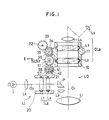
- the lenses L 2 and L 3 of the zooming system OL z can be moved along the optical axis 0 1 to change the magnification for observation, by means of a known lens moving mechanism which includes a cam lens-barrel 10.
- the lenses L 7 and L 8 of the zoom illumination system IL z in the optical illuminating system LI can be moved along the optical axis 0 2 to change the magnitude of the illuminating field, by means of a known lens moving mechanism which includes a cam lens-barrel 20.
- the zooming system OL z may be driven by a first driving mechanism 30 which consists of a motor 31 as a source of driving force; a gear 33 rigidly mounted about the output shaft 32 of the motor 33; a gear 34 engaged by the gear 33; a driving shaft 36 firmly connected at one end with the gear 34 and including a worm gear 35 on the intermediate portion between the opposite ends of the driving shaft 36; and a worm gear 11 formed on and about the outer periphery of the cam lens-barrel 10 and engaged by the worm gear 35.
- a first driving mechanism 30 which consists of a motor 31 as a source of driving force; a gear 33 rigidly mounted about the output shaft 32 of the motor 33; a gear 34 engaged by the gear 33; a driving shaft 36 firmly connected at one end with the gear 34 and including a worm gear 35 on the intermediate portion between the opposite ends of the driving shaft 36; and a worm gear 11 formed on and about the outer periphery of the cam lens-barrel 10 and engaged by the worm gear
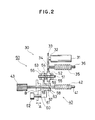
- the connecting mechanism 50 further comprises a gear 57 slidably mounted on the driving shaft 41 of the second driving mechanism 40 and having a hub formed with an axial slot 59 which is engaged by a pin 58 formed on the driving shaft 41, the rotational force of the gear 57 being transmitted to the driving shaft 41; and a connecting and operating member 60 slidably supported by a housing wall B to move in the direction of arrow A, the member 60 having at one end a bifurcated piece 61 disposed to receive the teeth of the gear 57, the other end thereof having a knob 62 which is located outside of the housing wall B.
- a stopper ring 63 is rigidly mounted on the driving shaft 41 to limit the axial movement of the gear 57.
- the worm gear 35 is driven to rotate the cam lens-barrel 10 such that the lenses L 2 and L 3 in the zooming system will be shifted to change the magnification.
- the rotation of the motor 31 is transmitted to rotate the worm gear 42 through the gear train (33, 34, 52, 53 and 57) to rotate the cam lens-barrel 20 such that the lenses L 7 and L 8 in the zoom illuminating system will be shifted to change the illuminating field in connection with the change of magnification in the zooming system OL 2 .
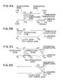
- the illuminating field is simultaneously changed from 4) 5 to ⁇ 10.
- the worm gear 35 is rotated to further move the lenses L 2 and L 3 to increase the observing magnification.
- the rotation of the motor 31 is interrupted at the gear 53 of the gear train (33, 34, 52 and 53) to stop the worm gear 42. Therefore, the lenses L 7 and L 8 will not be moved to further decrease the illuminating field. In other words, the illuminating field will be maintained at 4) l o corresponding to the observing magnification 10X although the latter is increased from 10X to 15X as in Figure 5A.
- the illuminating field can be changed only up to a value 4)20 even if the observing magnification is increased to the maximum magnification 25X to move the lenses L 2 and L 3 to its maximum movement point.
- the connecting and operating member 60 may be manipulated to reset the non-interlocking condition.
- the manual rotatable knob 43 may be also actuated to rotate the worm gear 42 to move the lenses L 7 and L 8 such that the illuminating field will be changed to the limit thereof, 4)25.
- the connecting and operating member 60 may not be manipulated to maintain the interlocking condition while the motor 31 may be reversed in rotation.
- the illuminating field will be returned from 4)20 back to ⁇ 5 while the observing magnification is returned from the maximum level 25X back to the minimum level 5X.
- the illuminating field reaches the maximum level, ⁇ 5. Since at this time the lenses L 7 and L 8 reaches their maximum illuminating field, the cam lens-barrel 20 in the zoom illuminating system IL z cannot be further rotated even though the motor 31 is energized to return the observing magnification to 5X.
- the gear train consisting of the worm gears 21, 42, the gear 57 and gear 53 serves as braking means.
- the gear 52 engaged by the gear 34 will have a lost-motion zone since the gear 53 is braked. In this lost-motion zone, the gear 52 is run idle about the intermediate shaft 51 against the frictional connecting force between the gear 53 and the spring 54 in the clutch-gear mechanism. Therefore, the motor 31 is energized only to rotate the worm gear 35 such that merely the zooming system OL z will be actuated to return the observing magnification to the minimum level, 5X. Thereafter, if the motor 31 is reenergized forwardly, the first driving mechanism can be interlocked again with the second driving mechanism to change the observing magnification and the illuminating field simultaneously.
- Figure 5C illustrates the case where the first driving mechanism is actuated with the second driving mechanism interlocked therewith to obtain the observing magnification equal to 10X and thereafter the connecting and operating member 60 is actuated to release the first and second driving mechanisms 30, 40 from each other so that the manual rotatable knob 43 can be manipulated to decrease the illuminating field to ⁇ 15 independently.
- the knob 43 can be more easily manipulated by operating the connecting and operating member 60 to release the interlocking condition. In the first embodiment, however, only the rotation of the knob 43 can rotate the driving shaft 41 without disengagement of the first driving mechanism 30 with the second one 40.
- the second driving mechanism 40 for actuating the zoom illuminating system IL z comprises a second driving shaft 41 having a worm gear 23 formed thereon and engaged by the worm gear 42, and feed screws 24 and 25.
- the rotation of the second driving shaft 41 is transmitted to the third driving shaft 22 to move the lenses L 7 and L 8 along the optical axis O z through the feed screws 24 and 25 in the known manner.
- the connecting and operating member 60 is in the form of a rotatable arm 64 which is rotatably fitted about the second driving shaft 41 and which is connected with a manipulating knob 62.
- the intermediate shaft 51 in the connecting mechanism 50 is rotatably mounted on the rotatable arm 64 at one end.
- a gear 44 is rigidly mounted on the second driving shaft.
- the gear 34 in the first driving mechanism is rotatably fitted over the first driving shaft 36 and provides part of a clutch-gear mechanism defined by a spring 37 and stopper rings 38 and 39.
- the gear 34 is biased toward one of the stopper rings 38 under the action of the spring 37.
- the interlocking condition between the first and second driving mechanisms 30 and 40 can be set by rotating the manipulating knob 62 about the second driving shaft 41 in the direction of arrow C in Figure 3 so that the gear 52 in the clutch-gear mechanism will be engaged with the gear 34 through the gear 33 rigidly mounted on the output shaft 32 of the motor 31.
- the non-interlocking condition can be set by separating the gear 33 away from the gear 52.
- the function of the second embodiment is substantially the same as that of the first embodiment except some differences which will be apparent hereinafter.
- the zooming system OL z reaches its limit point, for example, to provide the maximum observing magnification, 25X, as shown in Figure 5A and if the illuminating field in the zoom illuminating system is at its intermediate point (e.g. 4)20), the illuminating field should be manually changed to its minimum level ⁇ 25 or the observing magnification should be returned back to the minimum level under the interlocking condition as shown in Figure 5B.
- the motor 31 is energized after the observing magnification reaches its maximum level, 25X, as shown in Figure 6.
- the gear 34 is rotated in lost-motion by the clutch-gear mechanism including the spring 37 to arrest the rotation of the worm gear 35.
- the rotating force is transmitted from the motor 31 to the gear train (33, 52, 53, 44, 42, 23, 24 and 25) to continue the motion of the zoom illuminating system IL z such that the illuminating field will be changed independently to its minimum point 4)25.
- the first driving shaft 36 may be extended outwardly through the housing wall B with the outward end 36' thereof having a manipulating knob 70 detachably mounted thereon. With the rotation of the manipulating knob 70, the first driving shaft 36 can be rotated to change the magnification of the zooming system OL z through the worm gears 35 and 11. If the biasing force in the spring 37 of the clutch-gear mechanism against the gear 34 is established to be larger than that of the spring 54 of the clutch-gear mechanism in the connecting mechanism 50, the rotation of the manipulating knob 70 allows the simultaneous movement of the zooming and illuminating systems when both the systems are not in their limit points.
- the zoom illuminating system reaches its limit point, that is, the minimum level (4)25) as shown in Figure 7, merely the zooming system can be actuated.
- the manipulating knob 70 an advantage can be provided in that even if the motor 31 is not in use for any reason (e.g. power failure), the observing magnification and the illuminating field can be manually changed.
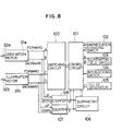
- the third embodiment provides an electrical interlocking mechanism as shown in Figure 8.
- the electrical interlocking mechanism comprises an observation motor 31 a having its output shaft 32a which is operatively connected with the first driving shaft 36 through the known reduction gear box (not shown).
- the electrical interlocking mechanism also comprises an illumination motor 31 b having its output shaft 32b which is operatively connected with the second or third driving shaft (41 or 22) through the known reduction gear box (not shown).
- the motors 31 a and 31 b are in the form of a pulse motor which has two input terminals on the forward and backward rotation sides. The pulse motor is adapted to be rotated forwardly or backwardly depending on pulses entered in either of the input terminals.
- the forward and backward input terminals of each of the motors 31 a and 31 are electrically connected with the corresponding pair of terminals (A and B; C and D) in the known switching circuit 100, respectively.
- the terminal A of the switching circuit 100 is coupled with the UP-side input terminal of the known Up-Down counter circuit 106 while the terminal B of the same is connected with the DOWN-side terminal of the counter circuit 106.
- the terminal C of the switching circuit 100 is connected with the UP-side input terminal of a similar Up-Down counter circuit 107 while the terminal D thereof is coupled with the DOWN-side input terminal of the counter circuit 107.
- Counted output signals from each of the counter circuit are applied to a subtracting circuit 108 and a control circuit 101 both of which are well-known in the art.
- the outputs of the subtracting circuit 108 are coupled to the control circuit 101.
- the control circuit 101 is constructed with a microprocessor and controls the switching circuit 100 such that it will be determined to provide pulses from a pulse generator 105 to any one of the terminals A through D in the switching circuit 100.
- the control circuit 101 also is connected with a magnification changing switch 102 known as a foot switch at the output terminal U thereof for generating command signal representative of the increase of magnification and at the output terminal D for generating command signal representative of the decrease of magnification.
- the control circuit 101 is further coupled with an illuminating field switch 103 in the form of a foot or hand switch at the output terminal N for generating command signal representative of the narrowing of illuminating field and at the output terminal W for generating command signal representative of the widening of illuminating field.
- An interlocking switch 104 for generating INTERLOCK signal also is coupled with the control circuit 101 and may be in the form of a foot or hand switch.
- control circuit 101 When a main switch (not shown) is turned on, the control circuit 101 is energized to position the motor 31 a at its minimum magnification location and the motor 31 b at its maximum illuminating field point and to initialize all of the counters 106, 107 and subtracting circuit 108.
- the interlocking switch 104 When it is wanted to shift the zooming system OL z and the zoom illuminating system IL z in the interlocking mode, the interlocking switch 104 is turned on. When received a signal from the interlocking switch 104, the control circuit 101 causes the terminals A and C of the switching circuit 100 to be turned on.
- the magnification changing switch is then actuated to provide the command signal representative of increase of magnification from its terminal II and while the command signals are being applied to the control circuit 101, pulses from the pulse generator 105 to apply to the motors 31 a and 31 b through the terminals A and C of the switching circuit 100 such that these motors 31 a and 31 b will be rotated forwardly to actuate the zooming and illuminating systems simultaneously to increase the observing magnification and at the same time to narrow the illuminating field.
- pulse outputs from the terminals A and C of the switching circuit 100 are entered into the terminals U of the counters 106 and 107. As a result, the pulses are upwardly counted in the counters 106 and 107. If the magnification changing switch 102 is stopped, the control circuit 101 turns off the terminals A and C of the switching circuit 100 to deenergize the motors 31 a and 31 b.
- the control circuit 101 receives the command signals through the terminal D of the switch 102 and then turns on the terminals B and D of the switching circuit 100. While the command signals are being applied from the switch 102 to the control circuit 101, pulses are supplied from the pulse generator 105 to the motors 31 a and 31 b to rotate them in the backward direction. Thus, the zooming and illuminating systems can be shifted to decrease the observing magnification and at the same time to widen the illuminating field. Pulses from the terminals C and D are downwardly counted by the counters 106 and 107.
- the control circuit 101 After the interlocking switch 104 has been turned off and when the magnification changing switch 102 is actuated, the control circuit 101 turns on the terminal A of the switching circuit 100 in accordance with the output of the terminal U of the switch 102 and the terminal B of the same in accordance with the output of the terminal D of the switch 102. As a result, pulses are applied from the pulse generator 105 to the motor 31 a to rotate forwardly or backwardly such that the zooming system DL will be only actuated to change the observing magnification.
- Pulse outputs from the terminal A or B is entered into the counter 106 wherein the number of pulses is counted up or down, alternatively.
- the interlocking switch 104 If the interlocking switch 104 is in its OFF state and when the illuminating field changing switch 103 is actuated to apply the command signals from its output terminal N to the control circuit 101, the latter turns on the terminal C of the switching circuit 100 so that the pulses will be transferred to the motor 31 b to energize it forwardly.
- the circuit 101 turns on the terminal D of the switching circuit 100 such that the pulses will be entered into the motor 31 b to rotate it in the backward direction.
- the zoom illuminating system IL z can be actuated independently.
- the pulses from the terminals C and D of the switching circuit 100 are counted up or down by the counter 107.
- the illuminating field will be interrelated with that observing magnification.
- the magnification changing switch 102 is again actuated to turn on the set of terminals A and C or terminals B and D in the switching circuit, depending on the operational command from the switch 102. In such a manner, the zooming and illuminating systems will be actuated simultaneously.
- the control circuit 101 turns on the terminal D of the switching circuit 100 to enter pulses corresponding to the absolute value m - f.
- the motor 31 b is rotated in the backward direction to interrelate the illuminating field with that observing magnification.
- the motors 31 a and 31 b will be simultaneously rotated forwardly or backwardly in accordance with the command from the magnification changing switch 102 so that the zooming and illuminating systems OL z , IL z can be actuated simultaneously.
- the present invention can use a known turret type magnification changing system wherein a plurality of lenses having different magnifications are arranged around the periphery thereof and each of the lenses can be selectively located in the optical path alternatively.
Claims (5)
gekennzeichnet durch
ein selektives Antriebsmittel (62, 60, 43) zum selektiven Antreiben des Vergrößerungs- änderungsmittels (OLz) und des Beleuchtungsfeldänderungsmittels (ILz) in einem gekoppelten Modus, in dem beide Änderungsmittel (OLz, ILz) miteinander verbunden sind und gleichzeitig betrieben werden, oder in einem ungekoppelten Modus, in dem beide Änderungsmittel (OLz, ILz) getrennt sind und unabhängig voneinander betrieben werden, wobei das selektive Antriebsmittel (62, 60, 43) einen Verbindungsmechanismus (53, 57) umfaßt, der selektiv mit dem zweiten Antriebsmechanismus (40, 41) verbindbar ist, um eine Antriebskraft von dem Antriebsmittel (31) auf den zweiten Antriebsmechanimus (40, 41) zu übertragen, und wobei von dem ersten Antriebsmechanismus (30), dem zweiten Antriebsmechanismus (40, 41) und dem Verbindungsmechanismus (53, 57) wenigstens einer ein Leerlaufübertragungsmittel (52, 53, 54) aufweist, um die Antriebskraft von dem Antriebsmittel (31) auf den ersten Antriebsmechanismus (30) im Leerlauf zu übertragen, wenn das optische Vergrößerungsänderungssystem (OLz, 20) bis zu seiner Bewegungsgrenze bewegt ist, und um die Antriebskraft von dem Antriebsmittel (31) auf den zweiten Antriebsmechanimus (40, 41) im Leerlauf zu übertragen, wenn das optische Beleuchtungsfeldänderungssystem (ILz) bis zu seiner Bewegungsgrenze bewegt ist.
Applications Claiming Priority (3)
| Application Number | Priority Date | Filing Date | Title |
|---|---|---|---|
| JP62162706A JP2855271B2 (ja) | 1987-06-30 | 1987-06-30 | 照明・観察光学装置 |
| JP162706/87 | 1987-06-30 | ||
| PCT/JP1988/000654 WO1989000298A1 (en) | 1987-06-30 | 1988-06-30 | Illumination/observation optical apparatus |
Publications (4)
| Publication Number | Publication Date |
|---|---|
| EP0321586A1 EP0321586A1 (de) | 1989-06-28 |
| EP0321586A4 EP0321586A4 (en) | 1990-10-10 |
| EP0321586B1 true EP0321586B1 (de) | 1993-12-29 |
| EP0321586B2 EP0321586B2 (de) | 1998-09-09 |
Family
ID=15759749
Family Applications (1)
| Application Number | Title | Priority Date | Filing Date |
|---|---|---|---|
| EP88906053A Expired - Lifetime EP0321586B2 (de) | 1987-06-30 | 1988-06-30 | Optisches beleuchtungs- und beobachtungsgerät |
Country Status (5)
| Country | Link |
|---|---|
| US (1) | US5140458A (de) |
| EP (1) | EP0321586B2 (de) |
| JP (1) | JP2855271B2 (de) |
| DE (1) | DE3886716T3 (de) |
| WO (1) | WO1989000298A1 (de) |
Cited By (3)
| Publication number | Priority date | Publication date | Assignee | Title |
|---|---|---|---|---|
| EP0595788A2 (de) * | 1993-04-28 | 1994-05-04 | J.D. Möller Optische Werke GmbH | Operationsmikroskop mit einer Beleuchtungseinrichtung |
| US5748367A (en) * | 1994-10-13 | 1998-05-05 | Carl-Zeiss-Stiftung | Illuminating device for a stereo microscope |
| EP1153569A3 (de) * | 2000-05-08 | 2004-01-02 | Leica Microsystems AG | Operationsmikroskop |
Families Citing this family (36)
| Publication number | Priority date | Publication date | Assignee | Title |
|---|---|---|---|---|
| US5258787A (en) * | 1989-10-16 | 1993-11-02 | Kowa Company Ltd. | Ophthalmologic apparatus |
| DE4331635C2 (de) * | 1992-12-22 | 2001-03-15 | Zeiss Carl Fa | Beleuchtungseinrichtung für ein Operationsmikroskop mit optisch-mechanisch gekoppelten Beobachtertuben |
| DE4243488A1 (de) * | 1992-12-22 | 1994-06-23 | Zeiss Carl Fa | Operationsmikroskop |
| EP0636525B1 (de) * | 1993-07-29 | 2000-06-14 | Sumitomo Wiring Systems, Ltd. | Steckverbindung |
| JP3548916B2 (ja) * | 1994-06-23 | 2004-08-04 | 株式会社トプコン | 実体顕微鏡 |
| DE19541237B4 (de) * | 1994-11-12 | 2006-04-13 | Carl Zeiss | Pankratisches Vergrößerungssystem |
| JP3401964B2 (ja) * | 1994-12-12 | 2003-04-28 | 株式会社ニコン | 顕微鏡 |
| JPH08220443A (ja) * | 1995-02-13 | 1996-08-30 | Olympus Optical Co Ltd | 顕微鏡のレボルバ装置 |
| EP1010030B1 (de) * | 1997-09-05 | 2001-11-14 | Leica Microsystems AG | Mikroskop, insbesondere fluoreszenzmikroskop, insbesondere stereo-fluoreszenzmikroskop |
| JP2002509287A (ja) | 1998-01-14 | 2002-03-26 | ライカ ミクロジュステムス ハイデルベルク ゲーエムベーハー | 顕微鏡の照明ビーム路内の光学装置 |
| DE19822255C2 (de) * | 1998-05-18 | 2001-07-05 | Zeiss Carl Jena Gmbh | Auflicht-Beleuchtungsanordnung für ein Stereomikroskop |
| US6637882B1 (en) | 1998-11-24 | 2003-10-28 | Welch Allyn, Inc. | Eye viewing device for retinal viewing through undilated pupil |
| JP2001166214A (ja) * | 1999-12-03 | 2001-06-22 | Olympus Optical Co Ltd | 光学装置 |
| JP3557174B2 (ja) * | 2000-05-02 | 2004-08-25 | 三鷹光器株式会社 | Mri用顕微鏡 |
| JP2002058017A (ja) * | 2000-08-10 | 2002-02-22 | Nidek Co Ltd | 映像配信装置 |
| JP3534733B2 (ja) * | 2001-12-28 | 2004-06-07 | 三鷹光器株式会社 | 固定高倍率切換型顕微鏡 |
| DE10340965A1 (de) * | 2003-09-05 | 2005-03-24 | Leica Microsystems Heidelberg Gmbh | Rastermikroskop |
| DE10355523A1 (de) * | 2003-11-21 | 2005-08-11 | Carl Zeiss Jena Gmbh | Auflicht-Fluoreszenz-Stereomikroskop |
| US8079950B2 (en) | 2005-09-29 | 2011-12-20 | Intuitive Surgical Operations, Inc. | Autofocus and/or autoscaling in telesurgery |
| DE102006022590C5 (de) * | 2006-05-15 | 2010-05-12 | Leica Microsystems (Schweiz) Ag | Beleuchtungseinheit für ein Mikroskop |
| JP2007310264A (ja) * | 2006-05-22 | 2007-11-29 | Nikon Corp | ズーム顕微鏡 |
| JP4968521B2 (ja) * | 2007-04-18 | 2012-07-04 | 株式会社ニコン | 顕微鏡 |
| JP5213417B2 (ja) * | 2007-04-24 | 2013-06-19 | カール・ツアイス・メディテック・アーゲー | Octシステムを備える手術用顕微鏡 |
| DE102007029893A1 (de) | 2007-06-28 | 2009-01-15 | Leica Microsystems (Schweiz) Ag | Mikroskop mit zentrierter Beleuchtung |
| DE102007029894A1 (de) | 2007-06-28 | 2009-01-15 | Leica Microsystems (Schweiz) Ag | Mikroskop mit zentrierter Beleuchtung |
| DE102007029896B3 (de) | 2007-06-28 | 2008-06-26 | Leica Microsystems (Schweiz) Ag | Mikroskop mit zentrierter Beleuchtung |
| DE102007029895B4 (de) | 2007-06-28 | 2014-01-16 | Leica Instruments (Singapore) Pte. Ltd. | Mikroskop mit zentrierter Beleuchtung |
| DE102007054686B4 (de) | 2007-11-14 | 2017-07-20 | Carl Zeiss Meditec Ag | Operationsmikroskop mit Beleuchtungssystem und Beleuchtungssystem-Steuereinheit |
| JP5036517B2 (ja) * | 2007-12-07 | 2012-09-26 | オリンパス株式会社 | ズーム顕微鏡 |
| DE102008015720B4 (de) * | 2008-03-26 | 2018-01-25 | Carl Zeiss Microscopy Gmbh | Beleuchtungsvorrichtung für ein Mikroskop und Fluoreszenzmikroskop mit derselben |
| DE102008026774B4 (de) * | 2008-06-04 | 2018-09-20 | Carl Zeiss Microscopy Gmbh | Steuerungseinrichtung für Stellglieder in Mikroskopobjektiven |
| JP5169637B2 (ja) * | 2008-09-01 | 2013-03-27 | 株式会社ニコン | 電動ズームユニットと、これを有するズーム顕微鏡 |
| DE102008041819A1 (de) * | 2008-09-04 | 2010-03-11 | Leica Microsystems (Schweiz) Ag | Optisches Abbildungssystem |
| DE102012006749B4 (de) * | 2012-04-03 | 2020-06-18 | Carl Zeiss Meditec Ag | Stereomikroskop |
| JP2013254764A (ja) | 2012-06-05 | 2013-12-19 | Hamamatsu Photonics Kk | 量子カスケードレーザ |
| CN106707487B (zh) * | 2016-12-23 | 2019-03-15 | 卡尔蔡司医疗技术股份公司 | 手术显微镜及使其在多种工作模式之间切换的装置 |
Family Cites Families (17)
| Publication number | Priority date | Publication date | Assignee | Title |
|---|---|---|---|---|
| JPS5317352A (en) * | 1976-07-30 | 1978-02-17 | Tokyo Optical | Microscope having variable magnification optical system |
| US4265518A (en) * | 1977-06-30 | 1981-05-05 | Canon Kabushiki Kaisha | Variable magnification apparatus having illumination compensating ability |
| US4331392A (en) * | 1977-08-16 | 1982-05-25 | Tokyo Kogaku Kikai Kabushiki Kaisha | Ophthalmoscopic slit lamp |
| JPS54122680U (de) * | 1978-02-17 | 1979-08-28 | ||
| US4235540A (en) * | 1978-05-10 | 1980-11-25 | Tokyo Kogaku Kikai Kabushiki Kaisha | Eye fundus camera having variable power photographing optical system |
| US4289378A (en) * | 1978-06-21 | 1981-09-15 | Ernst Remy | Apparatus for adjusting the focal point of an operating laser beam focused by an objective |
| DE2946927C2 (de) * | 1979-11-21 | 1983-07-07 | Fa. Carl Zeiss, 7920 Heidenheim | Automatische Durchlichtbeleuchtung für Mikroskope |
| JPS5776606U (de) * | 1980-10-31 | 1982-05-12 | ||
| US4443076A (en) * | 1981-10-20 | 1984-04-17 | Mitutoyo Mfg. Co., Ltd. | Projecting apparatus |
| DE3221804A1 (de) * | 1982-06-07 | 1983-12-08 | Leisegang Feinmechanik-Optik Gmbh & Co Kg, 1000 Berlin | Beleuchtungseinrichtung |
| JPS5949737A (ja) * | 1982-09-16 | 1984-03-22 | 株式会社トプコン | 眼底カメラの照明装置 |
| US4571038A (en) * | 1982-11-08 | 1986-02-18 | Jako Geza J | Binocular zoom microscope |
| JPS59141226A (ja) * | 1983-02-02 | 1984-08-13 | Canon Inc | 観察装置 |
| JPS59172617A (ja) * | 1983-03-22 | 1984-09-29 | Olympus Optical Co Ltd | 自動制御式照明光学系を備えた顕微鏡 |
| JPS6160220U (de) * | 1984-09-25 | 1986-04-23 | ||
| JPS61116310A (ja) * | 1984-11-12 | 1986-06-03 | Nippon Kogaku Kk <Nikon> | 変倍装置 |
| US4725720A (en) * | 1985-05-27 | 1988-02-16 | Mitutoyo Manufacturing Co., Ltd. | Microscope with auto focus and light adjusting means |
-
1987
- 1987-06-30 JP JP62162706A patent/JP2855271B2/ja not_active Expired - Fee Related
-
1988
- 1988-06-30 DE DE3886716T patent/DE3886716T3/de not_active Expired - Fee Related
- 1988-06-30 US US07/329,898 patent/US5140458A/en not_active Expired - Lifetime
- 1988-06-30 WO PCT/JP1988/000654 patent/WO1989000298A1/ja active IP Right Grant
- 1988-06-30 EP EP88906053A patent/EP0321586B2/de not_active Expired - Lifetime
Cited By (3)
| Publication number | Priority date | Publication date | Assignee | Title |
|---|---|---|---|---|
| EP0595788A2 (de) * | 1993-04-28 | 1994-05-04 | J.D. Möller Optische Werke GmbH | Operationsmikroskop mit einer Beleuchtungseinrichtung |
| US5748367A (en) * | 1994-10-13 | 1998-05-05 | Carl-Zeiss-Stiftung | Illuminating device for a stereo microscope |
| EP1153569A3 (de) * | 2000-05-08 | 2004-01-02 | Leica Microsystems AG | Operationsmikroskop |
Also Published As
| Publication number | Publication date |
|---|---|
| DE3886716D1 (de) | 1994-02-10 |
| EP0321586A1 (de) | 1989-06-28 |
| EP0321586A4 (en) | 1990-10-10 |
| EP0321586B2 (de) | 1998-09-09 |
| JP2855271B2 (ja) | 1999-02-10 |
| JPS646913A (en) | 1989-01-11 |
| DE3886716T2 (de) | 1994-04-28 |
| US5140458A (en) | 1992-08-18 |
| DE3886716T3 (de) | 1999-04-08 |
| WO1989000298A1 (en) | 1989-01-12 |
Similar Documents
| Publication | Publication Date | Title |
|---|---|---|
| EP0321586B1 (de) | Optisches beleuchtungs- und beobachtungsgerät | |
| US5546233A (en) | Lens barrel using a surface wave motor | |
| US4456356A (en) | Focus adjusting device of a camera | |
| GB2210704A (en) | Zoom mechanism for zoom lenses | |
| US4491396A (en) | Automatic focusing zoom lens mounting | |
| JPH02501863A (ja) | 光学的構成要素のためのレボルバー回転装置並びにこの回転装置の回転数を調整する方法 | |
| US5198935A (en) | Lens barrel with ultrasonic wave motor | |
| US4730201A (en) | Automatic focus adjustment apparatus | |
| US5572373A (en) | Photographing lens switchable between manual-focus and auto-focus modes | |
| US7180689B2 (en) | Lens tube of microscope | |
| EP1560055B1 (de) | Optische Vorrichtung | |
| EP0525315B1 (de) | Binokulares Fernrohr | |
| US5293193A (en) | Automatic focusing camera with control of focusing optical system position and driving power source velocity | |
| US5243374A (en) | Lens barrel having a power zooming function and a camera system | |
| EP0265934A1 (de) | Kamera | |
| JPS60252312A (ja) | レンズ駆動装置 | |
| JPS6345563B2 (de) | ||
| US6922525B2 (en) | Camera and modular lens system | |
| JP2598809Y2 (ja) | ターゲット電動切換装置 | |
| JPS6198310A (ja) | レンズ駆動装置 | |
| JP2770787B2 (ja) | レンズ鏡筒 | |
| JP2556060B2 (ja) | ズームレンズ | |
| JPH04338447A (ja) | 合焦モード選択可能な眼科撮影装置 | |
| JP2654278B2 (ja) | オートフォーカス機能を持つ結像装置 | |
| HU195984B (en) | Motion changing device for gripper loom |
Legal Events
| Date | Code | Title | Description |
|---|---|---|---|
| PUAI | Public reference made under article 153(3) epc to a published international application that has entered the european phase |
Free format text: ORIGINAL CODE: 0009012 |
|
| AK | Designated contracting states |
Kind code of ref document: A1 Designated state(s): CH DE LI |
|
| 17P | Request for examination filed |
Effective date: 19890619 |
|
| RAP1 | Party data changed (applicant data changed or rights of an application transferred) |
Owner name: KABUSHIKI KAISHA TOPCON |
|
| RAP1 | Party data changed (applicant data changed or rights of an application transferred) |
Owner name: KABUSHIKI KAISHA TOPCON |
|
| A4 | Supplementary search report drawn up and despatched |
Effective date: 19900822 |
|
| AK | Designated contracting states |
Kind code of ref document: A4 Designated state(s): CH DE LI |
|
| 17Q | First examination report despatched |
Effective date: 19920811 |
|
| GRAA | (expected) grant |
Free format text: ORIGINAL CODE: 0009210 |
|
| AK | Designated contracting states |
Kind code of ref document: B1 Designated state(s): CH DE LI |
|
| REF | Corresponds to: |
Ref document number: 3886716 Country of ref document: DE Date of ref document: 19940210 |
|
| PLBI | Opposition filed |
Free format text: ORIGINAL CODE: 0009260 |
|
| 26 | Opposition filed |
Opponent name: FIRMA CARL ZEISS Effective date: 19940926 |
|
| PLAW | Interlocutory decision in opposition |
Free format text: ORIGINAL CODE: EPIDOS IDOP |
|
| PLAW | Interlocutory decision in opposition |
Free format text: ORIGINAL CODE: EPIDOS IDOP |
|
| PUAH | Patent maintained in amended form |
Free format text: ORIGINAL CODE: 0009272 |
|
| STAA | Information on the status of an ep patent application or granted ep patent |
Free format text: STATUS: PATENT MAINTAINED AS AMENDED |
|
| 27A | Patent maintained in amended form |
Effective date: 19980909 |
|
| AK | Designated contracting states |
Kind code of ref document: B2 Designated state(s): CH DE LI |
|
| REG | Reference to a national code |
Ref country code: CH Ref legal event code: AEN Free format text: AUFRECHTERHALTUNG DES PATENTES IN GEAENDERTER FORM |
|
| PGFP | Annual fee paid to national office [announced via postgrant information from national office to epo] |
Ref country code: DE Payment date: 20040830 Year of fee payment: 17 |
|
| PGFP | Annual fee paid to national office [announced via postgrant information from national office to epo] |
Ref country code: CH Payment date: 20040902 Year of fee payment: 17 |
|
| PG25 | Lapsed in a contracting state [announced via postgrant information from national office to epo] |
Ref country code: LI Free format text: LAPSE BECAUSE OF NON-PAYMENT OF DUE FEES Effective date: 20050630 Ref country code: CH Free format text: LAPSE BECAUSE OF NON-PAYMENT OF DUE FEES Effective date: 20050630 |
|
| PG25 | Lapsed in a contracting state [announced via postgrant information from national office to epo] |
Ref country code: DE Free format text: LAPSE BECAUSE OF NON-PAYMENT OF DUE FEES Effective date: 20060103 |
|
| REG | Reference to a national code |
Ref country code: CH Ref legal event code: PL |