EP0320249A1 - Montage d'un connecteur étanche - Google Patents
Montage d'un connecteur étanche Download PDFInfo
- Publication number
- EP0320249A1 EP0320249A1 EP88311608A EP88311608A EP0320249A1 EP 0320249 A1 EP0320249 A1 EP 0320249A1 EP 88311608 A EP88311608 A EP 88311608A EP 88311608 A EP88311608 A EP 88311608A EP 0320249 A1 EP0320249 A1 EP 0320249A1
- Authority
- EP
- European Patent Office
- Prior art keywords
- housing
- terminal
- connector
- seal
- connector cover
- Prior art date
- Legal status (The legal status is an assumption and is not a legal conclusion. Google has not performed a legal analysis and makes no representation as to the accuracy of the status listed.)
- Granted
Links
- 239000004020 conductor Substances 0.000 claims description 35
- 230000013011 mating Effects 0.000 claims description 13
- 230000006835 compression Effects 0.000 claims description 4
- 238000007906 compression Methods 0.000 claims description 4
- 230000000875 corresponding effect Effects 0.000 claims 3
- 230000007246 mechanism Effects 0.000 abstract 1
- 238000003780 insertion Methods 0.000 description 6
- 230000037431 insertion Effects 0.000 description 6
- 239000000463 material Substances 0.000 description 4
- 238000007789 sealing Methods 0.000 description 4
- 238000011109 contamination Methods 0.000 description 3
- 238000004140 cleaning Methods 0.000 description 2
- XUIMIQQOPSSXEZ-UHFFFAOYSA-N Silicon Chemical compound [Si] XUIMIQQOPSSXEZ-UHFFFAOYSA-N 0.000 description 1
- 238000010276 construction Methods 0.000 description 1
- 239000000356 contaminant Substances 0.000 description 1
- 239000013536 elastomeric material Substances 0.000 description 1
- 239000012777 electrically insulating material Substances 0.000 description 1
- 238000001746 injection moulding Methods 0.000 description 1
- 238000000034 method Methods 0.000 description 1
- 239000003921 oil Substances 0.000 description 1
- 229910052710 silicon Inorganic materials 0.000 description 1
- 239000010703 silicon Substances 0.000 description 1
Images
Classifications
-
- H—ELECTRICITY
- H01—ELECTRIC ELEMENTS
- H01R—ELECTRICALLY-CONDUCTIVE CONNECTIONS; STRUCTURAL ASSOCIATIONS OF A PLURALITY OF MUTUALLY-INSULATED ELECTRICAL CONNECTING ELEMENTS; COUPLING DEVICES; CURRENT COLLECTORS
- H01R13/00—Details of coupling devices of the kinds covered by groups H01R12/70 or H01R24/00 - H01R33/00
- H01R13/46—Bases; Cases
- H01R13/52—Dustproof, splashproof, drip-proof, waterproof, or flameproof cases
- H01R13/5205—Sealing means between cable and housing, e.g. grommet
- H01R13/5208—Sealing means between cable and housing, e.g. grommet having at least two cable receiving openings
-
- H—ELECTRICITY
- H01—ELECTRIC ELEMENTS
- H01R—ELECTRICALLY-CONDUCTIVE CONNECTIONS; STRUCTURAL ASSOCIATIONS OF A PLURALITY OF MUTUALLY-INSULATED ELECTRICAL CONNECTING ELEMENTS; COUPLING DEVICES; CURRENT COLLECTORS
- H01R13/00—Details of coupling devices of the kinds covered by groups H01R12/70 or H01R24/00 - H01R33/00
- H01R13/40—Securing contact members in or to a base or case; Insulating of contact members
- H01R13/42—Securing in a demountable manner
- H01R13/422—Securing in resilient one-piece base or case, e.g. by friction; One-piece base or case formed with resilient locking means
- H01R13/4223—Securing in resilient one-piece base or case, e.g. by friction; One-piece base or case formed with resilient locking means comprising integral flexible contact retaining fingers
- H01R13/4226—Securing in resilient one-piece base or case, e.g. by friction; One-piece base or case formed with resilient locking means comprising integral flexible contact retaining fingers comprising two or more integral flexible retaining fingers acting on a single contact
-
- H—ELECTRICITY
- H01—ELECTRIC ELEMENTS
- H01R—ELECTRICALLY-CONDUCTIVE CONNECTIONS; STRUCTURAL ASSOCIATIONS OF A PLURALITY OF MUTUALLY-INSULATED ELECTRICAL CONNECTING ELEMENTS; COUPLING DEVICES; CURRENT COLLECTORS
- H01R13/00—Details of coupling devices of the kinds covered by groups H01R12/70 or H01R24/00 - H01R33/00
- H01R13/40—Securing contact members in or to a base or case; Insulating of contact members
- H01R13/42—Securing in a demountable manner
- H01R13/424—Securing in base or case composed of a plurality of insulating parts having at least one resilient insulating part
-
- H—ELECTRICITY
- H01—ELECTRIC ELEMENTS
- H01R—ELECTRICALLY-CONDUCTIVE CONNECTIONS; STRUCTURAL ASSOCIATIONS OF A PLURALITY OF MUTUALLY-INSULATED ELECTRICAL CONNECTING ELEMENTS; COUPLING DEVICES; CURRENT COLLECTORS
- H01R13/00—Details of coupling devices of the kinds covered by groups H01R12/70 or H01R24/00 - H01R33/00
- H01R13/46—Bases; Cases
- H01R13/502—Bases; Cases composed of different pieces
- H01R13/506—Bases; Cases composed of different pieces assembled by snap action of the parts
-
- H—ELECTRICITY
- H01—ELECTRIC ELEMENTS
- H01R—ELECTRICALLY-CONDUCTIVE CONNECTIONS; STRUCTURAL ASSOCIATIONS OF A PLURALITY OF MUTUALLY-INSULATED ELECTRICAL CONNECTING ELEMENTS; COUPLING DEVICES; CURRENT COLLECTORS
- H01R13/00—Details of coupling devices of the kinds covered by groups H01R12/70 or H01R24/00 - H01R33/00
- H01R13/64—Means for preventing incorrect coupling
-
- H—ELECTRICITY
- H01—ELECTRIC ELEMENTS
- H01R—ELECTRICALLY-CONDUCTIVE CONNECTIONS; STRUCTURAL ASSOCIATIONS OF A PLURALITY OF MUTUALLY-INSULATED ELECTRICAL CONNECTING ELEMENTS; COUPLING DEVICES; CURRENT COLLECTORS
- H01R4/00—Electrically-conductive connections between two or more conductive members in direct contact, i.e. touching one another; Means for effecting or maintaining such contact; Electrically-conductive connections having two or more spaced connecting locations for conductors and using contact members penetrating insulation
- H01R4/02—Soldered or welded connections
Definitions
- the present invention relates to sealed connectors and more particularly to a sealed connector and sealed connector subassembly including a housing for receiving at least one terminal terminating a conductor, a conductor entry seal and a connector cover.
- Sealed connectors are known for use in environments such as automobiles for environmentally sealing the electrical connections to prevent damage from moisture and other contaminants.
- One example of a sealed electrical connector is disclosed in United States Patent 4,497,531 issued February 5, 1985 to Baker.
- Disadvantages of known sealed connectors include complexity and the resulting difficulty and time required for assembly.
- a unitary subassembly for receiving terminals each with a terminated conductor.
- Such a unitary sealed connector subassembly should be adapted for automated assembly.
- Many prior art sealed connectors are provided as multiple parts for assembly by the user. Hence, possible misassembly and/or contamination with foreign material or dirt prior to assembly is a problem. This problem could be solved by a unitary subassembly.
- An object of the present invention is to provide an improved sealed connector.
- the present invention provides a sealed connector including at least one terminal with an associated terminated conductor.
- the sealed connector includes a housing having at least one terminal receiving channel extending from a terminal entry wall toward an opposed mating wall.
- the housing has at least one resilient arm with a free end finger extending within each of the terminal receiving channels for retaining the terminal within the terminal receiving channel.
- the housing includes a sleeve portion extending axially outwardly from the terminal entry wall defining a seal receiving cavity.
- a connector cover has at least one aperture for receiving the terminal.
- a seal has at least one aperture for receiving the terminal and is disposed within the seal receiving cavity between the housing terminal entry wall and the connector cover.
- the connector cover includes terminal position assurance means co-operating with the housing terminal retaining arm for securing the terminal within the terminal receiving channel.
- the housing and the connector cover include co-operating locking means for securing the connector cover to the housing.
- a sealed connector subassembly of the present invention for receiving at least one terminal with an associated conductor includes the connector housing, the connector cover and the seals.
- the housing and the connector cover include co-operating latching means for securing the connector cover to the housing in a subassembly position.
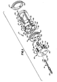
- the connector 10 includes a housing 12 for receiving and releasably securing a plurality of terminals 14 (only one being shown for clarity), a conductor entry seal 16, a terminal position assurance and locking cover 18 and a mating connector seal 20.
- a sealed connector subassembly generally designated as 22 of the sealed connector 10 includes the housing 12, the conductor entry seal 16, the terminal position assurance and locking cover 18 and the rear connector seal 20 assembled together.
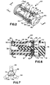
- the cover 18 and housing 12 are preassembled or partly assembled together as seen in FIGS. 2, 4 and 6.
- An associated conductor 24 (FIGS. 4 and 5) is terminated by each of the terminals 14 prior to insertion into the sealed connector subassembly 22.
- the terminal position assurance and locking cover 18 is moved into a locking position with the housing 12 as shown in FIGS. 5 and 10.
- the sealed connector housing 12 is an integral, one-piece member formed of a strong, flexible electrically insulating material.
- a translucent plastic or similar material forms the housing 12 by conventional injection molding technique.
- Housing 12 includes a plurality of spaced-apart channels 26 extending from a terminal entry wall 28 to an opposed mating wall 30.
- Each of the channels 26 has a size and shape for receiving and orienting the terminal 14.
- channels 26 have a generally rectangular shape to orient the terminal 14 so that either one of a pair of opposed locking windows 32 formed in each terminal 14 is positioned within the channel 26 facing radially inward.
- housing 12 is formed with a resilient retaining arm 34 outwardly extending within each of the terminal-receiving channels 26.
- Each retaining arm 34 has a free end locking finger 36 to be received within the terminal locking window 32 for locking the terminal 14 in place in a channel 26 of the housing 12.
- housing 12 includes a centrally located, generally D-shaped elongated recess 38 extending inwardly from the terminal entry wall 28 into an opposed housing cavity 39 (FIGS. 4-6) for keying and terminal position assurance features of the connector cover 18.
- the terminal receiving channels 26 are arrayed at approximately 120 degree intervals around and are spaced from the central longitudinal axis of housing 12 and recess 38 with the retaining arms 36 positioned for movement within the housing cavity 39.
- a sleeve 40 of the housing 12 extends axially outwardly from the terminal entry wall 28 defining a cavity 41 for receiving the conductor entry seal 16 and the connector cover 18.
- Sleeve 40 includes a plurality of spaced apart tab portions 42 and 44 having an aperture 46 and 48, respectively, cooperating with the connector cover 18 for securing the housing 12 with the connector cover 18 in the subassembly 22 and the sealed connector 10.
- there are two diametrically opposed tabs 42 alternating with two diametrically opposed tabs 44.
- Apertures 48 are shorter in axial length than apertures 46.
- housing 12 For accurate keying alignment with a mating connector (not shown) housing 12 includes a pair of rails 50, a latch protuberance 52 and a flat wall portion 54 (FIG. 3). Rails 50, latch protuberance 52 and flat wall portion 54 are adapted to be received in corresponding portions of the mating connector. Terminal pins or blades of the mating connector are oriented for receipt within the terminals 14. Housing 12 includes a groove 56 for receiving and retaining the mating connector seal 20.
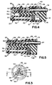
- the mating connector seal 20 and the conductor entry seal 16 are formed of an elastomeric material and impregnated with silicon oil or similar materials.
- a plurality of outwardly extending ribs 58 and 60 are defined by the outside surface of the mating connector seal 20 and the conductor entry seal 16, respectively.
- a cleaning wiping action of any contamination or foreign materials carried by the mating connector is provided by the first inserted rib 58.
- Effective compression sealing is provided by the subsequent ribs 58.
- the conductor entry seal 16 has an overall size for press-fit insertion within the housing cavity 41.
- Conductor entry seal 16 includes a plurality of generally circular passageways 62 sized for interference fit engagement with the conductors 24 and a centrally located, generally D-shaped opening 64 for keying alignment with the connector cover 18.
- a plurality of outwardly extending ribs 66 are defined by an inside surface of each of the passageways 62.
- a first rib 66 provides a cleaning wiping action of any contamination carried by the inserted conductor 24 with the remaining ribs providing effective compression sealing with the inserted conductor.
- the terminal position assurance and locking cover 18 includes an axially extending elongated keying member 70, a pair of outwardly extending latching protuberances 72 received within housing apertures 46 for retaining the cover 18 in the preassembled or partly assembled condition within recess 41 of the housing 12 in the subassembly 22 (FIG. 2) and a pair of outwardly extending locking protuberances 74 received within housing apertures 48 for securing the cover 18 to the housing 12 in the final assembled condition of the sealed connector 10.
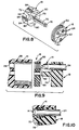
- Keying member 70 has a generally D-shape for keying alignment within D-shaped opening 64 within the conductor entry seal 16 and within the centrally located D-shaped elongated recess 38 of the housing 12. Keying member 70 includes a tapered nose portion 76 that facilitates the sliding insertion within the seal opening 64 and the housing recess 38. Keying member 70 includes a tapered base portion 78 for enhanced compression sealing with the conductor entry seal 16 as illustrated in FIG. 10.
- a plurality of spaced apart, generally circular shaped apertures 80 extend through a body portion 82 of the terminal position assurance and locking cover 18 for receiving and orienting the terminals 14.
- a plurality of radially extending ledges 84 define mating recesses 86 for receiving the housing tabs 42 and 44.
- the keying member 70 of the terminal position assurance and locking cover 18 extends through the seal opening 64 and into the housing recess 38 to align the terminal receiving apertures 80 and 62 with respective housing channels 26.
- the terminal position assurance and locking cover 18 is secured to the housing 12 in the preassembled condition by the latching protuberances 72 received within the housing apertures 46. In this condition, protuberances 74 are not in engagement with tabs 44.
- Fig. 6 illustrates the sealed connector subassembly 22 prior to the insertion of the terminals 14 with the terminated conductors 24 into the housing 12.
- the retaining arms 34 are molded to resiliently bias the locking fingers 36 of the resilient retaining arms 34 to extend within the housing recesses 26 as shown in Fig. 6.
- the locking fingers 36 of the retaining arms 34 are deflected radially inwardly as shown in Fig. 4 within the rear housing cavity 39 and in broken line in Fig. 7.
- the associated locking finger 36 moves within the terminal locking window 32 providing tactile and audible user feedback indication.
- terminal position assurance and locking cover 18 is moved into locking position as shown in Fig. 5.
- Keying member 70 engages each of the retaining arms 34 to retain the locking fingers 36 in a positively locking position in the terminal locking windows 32. If the terminals 14 are not fully inserted and/or properly positioned within the housing recesses 26, movement of the terminal position assurance and locking cover 18 into locking position is prevented.
- protuberances 72 move axially along apertures 46.
- Protuberances 74 engage tabs 44, deflect the tabs and then enter apertures 48 to lock cover 18 into place in housing 12 in the final position.
- Seal 16 is compressed in the axial direction between body 82 of cover 18 and wall 28 of housing 12 and is compressed radially by portion 78 of keying member 70. A reliable seal is made to each conductor 24, to the housing 12 and to the cover 18.
- removal of a terminal 14 is enabled by pulling the locking cover 18 outwardly to move the keying member 70 to the subassembly latching position.
- a tool (not shown) is inserted in the direction indicated by arrow labelled 90. Force is applied against the free end of the retaining arm 34 to release the locking finger 36 from the locking window 32 as indicated by an arrow labelled 92. Then the terminal 14 can be removed for repair or replacement.
- the connector 10 is simple and inexpensive to make and to assemble.
- the connector 10 is of a small size.
- the connector 10 includes terminals locking and and terminal position assurance features.
- the connector 10 has terminals 14 which can be released and replaced.
- the subassembly 22 has terminals 14 with terminated conductors which can be easily inserted without the necessity for special care or skilled labour.
- the subassembly 22 has a connector cover, a conductor entry seal and a housing mechanically secured and precisely aligned in a simple and automatic manner.
Landscapes
- Connector Housings Or Holding Contact Members (AREA)
Applications Claiming Priority (2)
| Application Number | Priority Date | Filing Date | Title |
|---|---|---|---|
| US07/130,144 US4776813A (en) | 1987-12-08 | 1987-12-08 | Sealed connector assembly |
| US130144 | 1987-12-08 |
Publications (2)
| Publication Number | Publication Date |
|---|---|
| EP0320249A1 true EP0320249A1 (fr) | 1989-06-14 |
| EP0320249B1 EP0320249B1 (fr) | 1993-08-04 |
Family
ID=22443272
Family Applications (1)
| Application Number | Title | Priority Date | Filing Date |
|---|---|---|---|
| EP88311608A Expired - Lifetime EP0320249B1 (fr) | 1987-12-08 | 1988-12-08 | Montage d'un connecteur étanche |
Country Status (8)
| Country | Link |
|---|---|
| US (1) | US4776813A (fr) |
| EP (1) | EP0320249B1 (fr) |
| JP (1) | JPH07118346B2 (fr) |
| KR (1) | KR970000124B1 (fr) |
| BR (1) | BR8806372A (fr) |
| CA (1) | CA1295026C (fr) |
| DE (1) | DE3882935T2 (fr) |
| ES (1) | ES2042771T3 (fr) |
Cited By (5)
| Publication number | Priority date | Publication date | Assignee | Title |
|---|---|---|---|---|
| EP0529463A3 (en) * | 1991-08-28 | 1993-05-12 | The Whitaker Corporation | Seals for an electrical connector |
| EP0592102A3 (fr) * | 1992-10-06 | 1995-03-22 | Whitaker Corp | Connecteur électrique étanche. |
| FR2764128A1 (fr) * | 1997-05-29 | 1998-12-04 | Proner Comatel Sa | Verrou secondaire pour connecteur electrique |
| EP1261075A1 (fr) * | 2001-05-18 | 2002-11-27 | Sumitomo Wiring Systems, Ltd. | Un connecteur étanche et un procédé pour son assemblage |
| AT505774B1 (de) * | 2007-11-15 | 2009-04-15 | Sterner Franz | Gehause zur aufnahme von kabelenden |
Families Citing this family (54)
| Publication number | Priority date | Publication date | Assignee | Title |
|---|---|---|---|---|
| JPH07101621B2 (ja) * | 1987-06-16 | 1995-11-01 | 住友電装株式会社 | コネクタ |
| US4826452A (en) * | 1987-10-16 | 1989-05-02 | Altair International, Inc. | Two-part electrical connector |
| JPH0430793Y2 (fr) * | 1988-05-06 | 1992-07-24 | ||
| JPH0357027Y2 (fr) * | 1988-05-06 | 1991-12-25 | ||
| JP2555394Y2 (ja) * | 1988-10-26 | 1997-11-19 | 日本エー・エム・ピー 株式会社 | コネクタ |
| GB8827756D0 (en) * | 1988-11-28 | 1988-12-29 | Amp Great Britain | Electrical connector housing assembly |
| US4900271A (en) * | 1989-02-24 | 1990-02-13 | Molex Incorporated | Electrical connector for fuel injector and terminals therefor |
| US4921437A (en) * | 1989-03-29 | 1990-05-01 | Amp Incorporated | Sealed electrical connector assembly with terminal retainer |
| US4944688A (en) * | 1989-09-25 | 1990-07-31 | Amp Incorporated | Programmable sealed connector |
| EP0424887B1 (fr) * | 1989-10-24 | 1996-04-03 | The Whitaker Corporation | Connecteur électrique avec des moyens secondaires de rétension améliorés |
| JPH0740303Y2 (ja) * | 1990-03-13 | 1995-09-13 | 住友電装株式会社 | 電気接続子とそれを用いるコネクタ |
| US5153818A (en) * | 1990-04-20 | 1992-10-06 | Rohm Co., Ltd. | Ic memory card with an anisotropic conductive rubber interconnector |
| US5044991A (en) * | 1990-11-05 | 1991-09-03 | Molex Incorporated | Electrical connector with terminal position assurance component |
| US5071369A (en) * | 1990-12-05 | 1991-12-10 | Amp Incorporated | Electrical connector having a terminal position assurance member |
| JP2586314Y2 (ja) * | 1991-11-08 | 1998-12-02 | 矢崎総業株式会社 | 防水コネクタ |
| JP2562613Y2 (ja) * | 1991-12-21 | 1998-02-16 | 住友電装株式会社 | 防水コネクタ |
| JP2901111B2 (ja) * | 1992-06-22 | 1999-06-07 | 矢崎総業株式会社 | 防水コネクタ |
| US5503569A (en) * | 1993-10-04 | 1996-04-02 | The Whitaker Corporation | Electrical connector with two stage latch for retaining contacts |
| JP2911020B2 (ja) * | 1994-03-28 | 1999-06-23 | 矢崎総業株式会社 | 電気接続端子 |
| JP2957084B2 (ja) * | 1994-04-08 | 1999-10-04 | 矢崎総業株式会社 | コネクタハウジング |
| JPH0864315A (ja) * | 1994-08-02 | 1996-03-08 | Molex Inc | リセプタクル型電気コネクタ |
| JP3109794B2 (ja) * | 1994-09-27 | 2000-11-20 | ヒロセ電機株式会社 | 防水コネクタ |
| DE19532381C2 (de) * | 1995-09-01 | 1999-11-11 | Siemens Ag | Elektrischer Verbinder mit Kontaktsicherungsschieber |
| US5730624A (en) * | 1995-11-30 | 1998-03-24 | Itt Corporation | Secondary contact lock arrangement |
| US5716233A (en) * | 1995-11-30 | 1998-02-10 | Itt Corporation | Contact position assurance device |
| DE29704689U1 (de) * | 1997-03-14 | 1997-05-15 | Intercontec GmbH, 94336 Hunderdorf | Kontaktträger für elektrische Vielfachsteckverbinder |
| JP3566541B2 (ja) * | 1998-03-31 | 2004-09-15 | 矢崎総業株式会社 | 防水コネクタ及び防水処理方法 |
| JP3566540B2 (ja) * | 1998-03-31 | 2004-09-15 | 矢崎総業株式会社 | 防水コネクタ |
| JP3517109B2 (ja) | 1998-03-31 | 2004-04-05 | 矢崎総業株式会社 | 防水コネクタ及び防水コネクタの組立方法 |
| JP3547988B2 (ja) | 1998-03-31 | 2004-07-28 | 矢崎総業株式会社 | 防水コネクタ及び防水処理方法 |
| JPH11354201A (ja) | 1998-06-10 | 1999-12-24 | Yazaki Corp | 防水コネクタ |
| JP3500065B2 (ja) | 1998-06-25 | 2004-02-23 | 矢崎総業株式会社 | 防水コネクタ |
| JP3540164B2 (ja) | 1998-07-06 | 2004-07-07 | 矢崎総業株式会社 | 防水コネクタ |
| JP3691291B2 (ja) * | 1999-06-28 | 2005-09-07 | 矢崎総業株式会社 | 防水コネクタ |
| US6409541B1 (en) * | 2000-11-02 | 2002-06-25 | Autonetworks Technologies, Ltd. | Waterproof structure in cable insertion section, method of manufacturing the same, and die for waterproof molding |
| JP3767460B2 (ja) | 2001-11-05 | 2006-04-19 | 住友電装株式会社 | 防水コネクタ |
| US7077701B2 (en) * | 2003-06-06 | 2006-07-18 | Tyco Electronics Corporation | Sealed electrical connector |
| US20050173098A1 (en) * | 2003-06-10 | 2005-08-11 | Connors Matthew J. | Three dimensional vapor chamber |
| US20050139995A1 (en) * | 2003-06-10 | 2005-06-30 | David Sarraf | CTE-matched heat pipe |
| DE102004053576B3 (de) * | 2004-11-05 | 2006-04-13 | Lisa Dräxlmaier GmbH | Schaltknauf und Schalthebel mit einem solchen Schaltknauf |
| US7097486B2 (en) * | 2005-02-03 | 2006-08-29 | Cushcraft Corporation | Low-cost weatherproof cable feedthrough |
| RU2319264C1 (ru) * | 2007-01-09 | 2008-03-10 | Сергей Евгеньевич Варламов | Соединитель электрический и способ его изготовления |
| US7473113B2 (en) * | 2007-03-31 | 2009-01-06 | Kojiro Koda | Electrical connection for high humidity and low temperature environments |
| JP5417954B2 (ja) * | 2009-04-09 | 2014-02-19 | 住友電装株式会社 | 防水コネクタ |
| JP2011198566A (ja) * | 2010-03-18 | 2011-10-06 | Sumitomo Wiring Syst Ltd | 充電用コネクタ |
| JP2012221797A (ja) * | 2011-04-11 | 2012-11-12 | Iriso Electronics Co Ltd | コネクタ |
| US8425244B2 (en) * | 2011-07-26 | 2013-04-23 | Motorola Solutions, Inc. | Connector with a locking sleeve for locking to a socket having a circular band |
| JP5970171B2 (ja) * | 2011-11-08 | 2016-08-17 | 富士電線工業株式会社 | 差込プラグ付きコードの製造方法 |
| US8974241B2 (en) | 2013-01-28 | 2015-03-10 | Itt Manufacturing Enterprises, Llc | Bracket for connector pin seals |
| JP6604512B2 (ja) * | 2016-02-24 | 2019-11-13 | 住友電装株式会社 | コネクタ |
| DE102018118774B4 (de) * | 2018-08-02 | 2022-07-14 | Harting Electric Gmbh & Co. Kg | Modulares Steckverbindersystem |
| JP6964105B2 (ja) * | 2019-03-14 | 2021-11-10 | ヒロセ電機株式会社 | コネクタおよびコネクタの組立方法 |
| TWM629291U (zh) | 2021-07-07 | 2022-07-11 | 大陸商富加宜電子(南通)有限公司 | 一種混合式連接器 |
| EP4160285B1 (fr) | 2021-09-29 | 2025-11-05 | Corning Research & Development Corporation | Connecteurs de fibres optiques comportant une membrane d'étanchéité disposée sur le boîtier de connecteur |
Citations (5)
| Publication number | Priority date | Publication date | Assignee | Title |
|---|---|---|---|---|
| US3937545A (en) * | 1974-12-23 | 1976-02-10 | Ford Motor Company | Waterproof electrical connector |
| EP0035378A2 (fr) * | 1980-02-28 | 1981-09-09 | General Signal Corporation | Connecteur électrique |
| EP0072104A1 (fr) * | 1981-07-23 | 1983-02-16 | AMP INCORPORATED (a New Jersey corporation) | Connecteur électrique scellé |
| US4714437A (en) * | 1987-01-20 | 1987-12-22 | Ford Motor Company | Electrical connector |
| DE3720751A1 (de) * | 1986-06-24 | 1988-01-07 | Amp Inc | Elektrische verbinderanordnung |
Family Cites Families (3)
| Publication number | Priority date | Publication date | Assignee | Title |
|---|---|---|---|---|
| JPS5921510Y2 (ja) * | 1982-03-19 | 1984-06-25 | 矢崎総業株式会社 | 防水コネクタ |
| JPS60249273A (ja) * | 1984-05-23 | 1985-12-09 | 日産自動車株式会社 | 接続端子の取付構造 |
| US4740177A (en) * | 1987-02-09 | 1988-04-26 | Standex International Corporation | Cluster assembly with locking tabs |
-
1987
- 1987-12-08 US US07/130,144 patent/US4776813A/en not_active Expired - Lifetime
-
1988
- 1988-11-14 CA CA000582939A patent/CA1295026C/fr not_active Expired - Lifetime
- 1988-12-02 BR BR888806372A patent/BR8806372A/pt unknown
- 1988-12-07 KR KR1019880016239A patent/KR970000124B1/ko not_active Expired - Fee Related
- 1988-12-07 JP JP63309782A patent/JPH07118346B2/ja not_active Expired - Lifetime
- 1988-12-08 ES ES88311608T patent/ES2042771T3/es not_active Expired - Lifetime
- 1988-12-08 DE DE88311608T patent/DE3882935T2/de not_active Expired - Fee Related
- 1988-12-08 EP EP88311608A patent/EP0320249B1/fr not_active Expired - Lifetime
Patent Citations (5)
| Publication number | Priority date | Publication date | Assignee | Title |
|---|---|---|---|---|
| US3937545A (en) * | 1974-12-23 | 1976-02-10 | Ford Motor Company | Waterproof electrical connector |
| EP0035378A2 (fr) * | 1980-02-28 | 1981-09-09 | General Signal Corporation | Connecteur électrique |
| EP0072104A1 (fr) * | 1981-07-23 | 1983-02-16 | AMP INCORPORATED (a New Jersey corporation) | Connecteur électrique scellé |
| DE3720751A1 (de) * | 1986-06-24 | 1988-01-07 | Amp Inc | Elektrische verbinderanordnung |
| US4714437A (en) * | 1987-01-20 | 1987-12-22 | Ford Motor Company | Electrical connector |
Cited By (5)
| Publication number | Priority date | Publication date | Assignee | Title |
|---|---|---|---|---|
| EP0529463A3 (en) * | 1991-08-28 | 1993-05-12 | The Whitaker Corporation | Seals for an electrical connector |
| EP0592102A3 (fr) * | 1992-10-06 | 1995-03-22 | Whitaker Corp | Connecteur électrique étanche. |
| FR2764128A1 (fr) * | 1997-05-29 | 1998-12-04 | Proner Comatel Sa | Verrou secondaire pour connecteur electrique |
| EP1261075A1 (fr) * | 2001-05-18 | 2002-11-27 | Sumitomo Wiring Systems, Ltd. | Un connecteur étanche et un procédé pour son assemblage |
| AT505774B1 (de) * | 2007-11-15 | 2009-04-15 | Sterner Franz | Gehause zur aufnahme von kabelenden |
Also Published As
| Publication number | Publication date |
|---|---|
| JPH01187783A (ja) | 1989-07-27 |
| KR890011147A (ko) | 1989-08-12 |
| CA1295026C (fr) | 1992-01-28 |
| KR970000124B1 (ko) | 1997-01-04 |
| DE3882935T2 (de) | 1994-01-13 |
| DE3882935D1 (de) | 1993-09-09 |
| ES2042771T3 (es) | 1993-12-16 |
| US4776813A (en) | 1988-10-11 |
| BR8806372A (pt) | 1989-08-22 |
| EP0320249B1 (fr) | 1993-08-04 |
| JPH07118346B2 (ja) | 1995-12-18 |
Similar Documents
| Publication | Publication Date | Title |
|---|---|---|
| EP0320249A1 (fr) | Montage d'un connecteur étanche | |
| CA2303161C (fr) | Ensemble de raccordement electrique male et femelle | |
| KR100190793B1 (ko) | 전기 커넥터 | |
| KR100501561B1 (ko) | 전기 터미널용 카울 커넥터 | |
| EP0726617B1 (fr) | Connecteur avec verrouillage secondaire et mécanisme d'accouplement | |
| EP0599165A1 (fr) | Connecteur électrique avec système d'alignement et d'arrêt en position pour éléments de contact | |
| US5967859A (en) | Electrical connector assembly with terminal retainer system | |
| EP0585633A1 (fr) | Dispositif de couplage verrouillable pour connecteur électrique | |
| US5435738A (en) | Lever-type connector | |
| EP0954060A2 (fr) | Connecteur électrique d'éléments de verrouillage secondaires déviables | |
| JPH10189115A (ja) | コネクタ | |
| EP0035378B1 (fr) | Connecteur électrique | |
| US5160279A (en) | Double lock connector | |
| EP0665453B1 (fr) | Assemblage de connecteur électrique | |
| KR100326219B1 (ko) | 단자위치보장장치를갖는전기커넥터 | |
| US5651704A (en) | Electrical connector with terminal retainer | |
| US4717359A (en) | Arrangement for securing electrical terminal in terminal holder | |
| EP1091452A1 (fr) | Connecteur électrique avec des pièces de rétention de contacts libres et moulées | |
| EP0877447B1 (fr) | Connecteur | |
| US4932899A (en) | Electrical connector | |
| JP2602469B2 (ja) | ロック自在の電気コネクタ組立体 | |
| EP3629423B1 (fr) | Connecteur électrique avec verrou en plastique intégré dans une cavité de contact | |
| EP0788670B1 (fr) | Ensemble connecteur etanche pourvu d'un systeme de verrouillage secondaire | |
| CN111834788A (zh) | 带有端子锁的电端子壳体 | |
| US5429525A (en) | Connector assembly |
Legal Events
| Date | Code | Title | Description |
|---|---|---|---|
| PUAI | Public reference made under article 153(3) epc to a published international application that has entered the european phase |
Free format text: ORIGINAL CODE: 0009012 |
|
| AK | Designated contracting states |
Kind code of ref document: A1 Designated state(s): DE ES FR GB IT SE |
|
| 17P | Request for examination filed |
Effective date: 19891125 |
|
| 17Q | First examination report despatched |
Effective date: 19920123 |
|
| GRAA | (expected) grant |
Free format text: ORIGINAL CODE: 0009210 |
|
| AK | Designated contracting states |
Kind code of ref document: B1 Designated state(s): DE ES FR GB IT SE |
|
| ITF | It: translation for a ep patent filed | ||
| REF | Corresponds to: |
Ref document number: 3882935 Country of ref document: DE Date of ref document: 19930909 |
|
| ET | Fr: translation filed | ||
| REG | Reference to a national code |
Ref country code: ES Ref legal event code: FG2A Ref document number: 2042771 Country of ref document: ES Kind code of ref document: T3 |
|
| PLBE | No opposition filed within time limit |
Free format text: ORIGINAL CODE: 0009261 |
|
| STAA | Information on the status of an ep patent application or granted ep patent |
Free format text: STATUS: NO OPPOSITION FILED WITHIN TIME LIMIT |
|
| 26N | No opposition filed | ||
| EAL | Se: european patent in force in sweden |
Ref document number: 88311608.9 |
|
| PGFP | Annual fee paid to national office [announced via postgrant information from national office to epo] |
Ref country code: GB Payment date: 20001107 Year of fee payment: 13 |
|
| PGFP | Annual fee paid to national office [announced via postgrant information from national office to epo] |
Ref country code: SE Payment date: 20001201 Year of fee payment: 13 |
|
| PGFP | Annual fee paid to national office [announced via postgrant information from national office to epo] |
Ref country code: FR Payment date: 20001204 Year of fee payment: 13 |
|
| PGFP | Annual fee paid to national office [announced via postgrant information from national office to epo] |
Ref country code: ES Payment date: 20001219 Year of fee payment: 13 |
|
| PGFP | Annual fee paid to national office [announced via postgrant information from national office to epo] |
Ref country code: DE Payment date: 20001222 Year of fee payment: 13 |
|
| PG25 | Lapsed in a contracting state [announced via postgrant information from national office to epo] |
Ref country code: GB Free format text: LAPSE BECAUSE OF NON-PAYMENT OF DUE FEES Effective date: 20011208 |
|
| PG25 | Lapsed in a contracting state [announced via postgrant information from national office to epo] |
Ref country code: SE Free format text: LAPSE BECAUSE OF NON-PAYMENT OF DUE FEES Effective date: 20011209 |
|
| REG | Reference to a national code |
Ref country code: GB Ref legal event code: IF02 |
|
| PG25 | Lapsed in a contracting state [announced via postgrant information from national office to epo] |
Ref country code: DE Free format text: LAPSE BECAUSE OF NON-PAYMENT OF DUE FEES Effective date: 20020702 |
|
| EUG | Se: european patent has lapsed |
Ref document number: 88311608.9 |
|
| GBPC | Gb: european patent ceased through non-payment of renewal fee |
Effective date: 20011208 |
|
| PG25 | Lapsed in a contracting state [announced via postgrant information from national office to epo] |
Ref country code: FR Free format text: LAPSE BECAUSE OF NON-PAYMENT OF DUE FEES Effective date: 20020830 |
|
| REG | Reference to a national code |
Ref country code: FR Ref legal event code: ST |
|
| PG25 | Lapsed in a contracting state [announced via postgrant information from national office to epo] |
Ref country code: ES Free format text: LAPSE BECAUSE OF NON-PAYMENT OF DUE FEES Effective date: 20021209 |
|
| REG | Reference to a national code |
Ref country code: ES Ref legal event code: FD2A Effective date: 20030113 |
|
| PG25 | Lapsed in a contracting state [announced via postgrant information from national office to epo] |
Ref country code: IT Free format text: LAPSE BECAUSE OF NON-PAYMENT OF DUE FEES Effective date: 20051208 |