EP0320087B1 - Combinaison de cellules électrochimiques à forme allongée - Google Patents
Combinaison de cellules électrochimiques à forme allongée Download PDFInfo
- Publication number
- EP0320087B1 EP0320087B1 EP88307054A EP88307054A EP0320087B1 EP 0320087 B1 EP0320087 B1 EP 0320087B1 EP 88307054 A EP88307054 A EP 88307054A EP 88307054 A EP88307054 A EP 88307054A EP 0320087 B1 EP0320087 B1 EP 0320087B1
- Authority
- EP
- European Patent Office
- Prior art keywords
- fuel
- cell
- electrode
- air
- metal fiber
- Prior art date
- Legal status (The legal status is an assumption and is not a legal conclusion. Google has not performed a legal analysis and makes no representation as to the accuracy of the status listed.)
- Expired - Lifetime
Links
Images

Classifications
-
- H—ELECTRICITY
- H01—ELECTRIC ELEMENTS
- H01M—PROCESSES OR MEANS, e.g. BATTERIES, FOR THE DIRECT CONVERSION OF CHEMICAL ENERGY INTO ELECTRICAL ENERGY
- H01M8/00—Fuel cells; Manufacture thereof
- H01M8/24—Grouping of fuel cells, e.g. stacking of fuel cells
- H01M8/241—Grouping of fuel cells, e.g. stacking of fuel cells with solid or matrix-supported electrolytes
- H01M8/2425—High-temperature cells with solid electrolytes
- H01M8/243—Grouping of unit cells of tubular or cylindrical configuration
-
- H—ELECTRICITY
- H01—ELECTRIC ELEMENTS
- H01M—PROCESSES OR MEANS, e.g. BATTERIES, FOR THE DIRECT CONVERSION OF CHEMICAL ENERGY INTO ELECTRICAL ENERGY
- H01M8/00—Fuel cells; Manufacture thereof
- H01M8/24—Grouping of fuel cells, e.g. stacking of fuel cells
- H01M8/241—Grouping of fuel cells, e.g. stacking of fuel cells with solid or matrix-supported electrolytes
- H01M8/2425—High-temperature cells with solid electrolytes
- H01M8/2432—Grouping of unit cells of planar configuration
-
- Y—GENERAL TAGGING OF NEW TECHNOLOGICAL DEVELOPMENTS; GENERAL TAGGING OF CROSS-SECTIONAL TECHNOLOGIES SPANNING OVER SEVERAL SECTIONS OF THE IPC; TECHNICAL SUBJECTS COVERED BY FORMER USPC CROSS-REFERENCE ART COLLECTIONS [XRACs] AND DIGESTS
- Y02—TECHNOLOGIES OR APPLICATIONS FOR MITIGATION OR ADAPTATION AGAINST CLIMATE CHANGE
- Y02E—REDUCTION OF GREENHOUSE GAS [GHG] EMISSIONS, RELATED TO ENERGY GENERATION, TRANSMISSION OR DISTRIBUTION
- Y02E60/00—Enabling technologies; Technologies with a potential or indirect contribution to GHG emissions mitigation
- Y02E60/30—Hydrogen technology
- Y02E60/50—Fuel cells
Definitions
- This invention relates to high-temperature, solid electrolyte, electrochemical cell combinations and the flexible connection of a plurality of such cell combinations.
- High temperature, solid oxide electrolyte fuel cell, and fuel cell generators are well known in the art, and are taught by Isenberg, in U.S. Patent Specification No. 4,395,468.
- These fuel cell configurations comprise a plurality of individual, series and parallel electronically connected, axially elongated, generally tubular, separately supported annular cells. Each cell was electronically connected in series to an adjacent cell in a column, through a narrow cell connection extending the full axial length of each cell. These connections contact the air electrode of one cell and the fuel electrode of an adjacent cell, through a conductive ceramic interconnection and a fiber metal felt strip.
- a single felt strip made, for example of nickel fibers, bonded at contact points, extended axially between the cells. In the preferred embodiment air was flowed inside the cells and gaseous fuel outside.
- Ackerman et al. in U.S. Patent Specification No. 4,476,198 taught a monolithic array of solid oxide electrolyte fuel cell elements.
- triangular air and fuel conduits with surrounding electrodes and solid electrolyte were all fused together into an inflexible, ceramic matrix.
- a plurality of plates were stacked, with ceramic interconnects between them and the whole fused to a single rigid structure.
- This fused, triangular-element structure is advantageous in that is was very compact, providing a high surface area to volume area, contained no inactive materials, and did not require a separate support structure, but, it is fragile, and provides little tolerance to thermal gradients or component shrinkage during fabrication and operation.
- Ackerman et al. similarly to Isenberg, had a generating section, containing the fuel cells, disposed between an oxidant preheating section and a fuel inlet section.
- None of these configurations provide a flat plate, repairable design that combines higher power density in larger individual cells, along with a flexible cell array structure that would not be sensitive to thermal gradients and stresses during start-up and operation.
- the invention consists in a high-temperature, solid oxide electrolyte, axially elongated electrochemical cell combination, of a flattened cross-sectional design, characterized in that said cell combination comprises a long, porous, air electrode of a flattened cross-sectional design having a top surface and a plurality of interior gas feed chambers parallel to its axial length; solid oxide electrolyte contacting the air electrode except for a major portion of the air electrode top surface; outer electrode contacting the electrolyte; non-porous, ceramic, electronically conducting interconnection material, contacting the air electrode and covering from 60% to 100% of the air electrode cross-sectional width not covered by electrolyte; and at least one axially elongated, electronically conductive, flexible, porous, metal fiber, current collector strip material on top of the interconnection material and in electronic connection with the air electrode through contact with a major portion of the interconnection material, the metal fiber strip being effective to connect additional cell combinations in series.
- the cell combination comprises an air electrode having a top surface and a plurality of gas feed chambers through its cross section and parallel to its axial length, electrolyte covering the air electrode except for a major portion of the air electrode top surface, which major portion of air electrode surface is covered by non-porous, ceramic interconnection material, and a fuel electrode contacting a major portion of the electrolyte, each cell combination having at least one axially elongated electronically conductive, flexible, porous, metal fiber felt current collector material in electronic connection with the air electrode through the interconnection material.
- the invention also resides in placing a plurality of these electrochemical cell combinations next to each other and, through the metal fiber felts, connecting them in series, to provide an electrochemical cell assembly.
- This assembly in turn can be placed in a housing where a first gaseous reactant is flowed to the air electrodes to contact the air electrodes, and a second gaseous reactant is flowed to the fuel electrodes to contact the fuel electrodes.
- a central electrochemical cell has its fuel electrode electronically contacted in series to the air electrode of the cell below it.
- Said electrochemical cell has its air electrode electronically connected in series to the fuel electrode of the cell above it.
- the air electrode is preferably self-supporting, and is electronically connected to the flexible, porous, metal fiber felts through an electronically conductive, non-porous, ceramic interconnection material.
- the cells are of a flattened design, having circular, square, triangular, or other type geometry for the interior gas conduits. This cell configuration permits large, top areas of the width of the cells to be connected, using a highly flexible, metal fiber felt, along the entire axial length of the cells, relieving stress during operation of the cell generator and making the cell stack configuration, non-rigid and non-fragile. Flattening the cell allows short electrical current paths and thinner air electrode walls, lowering gas diffusion resistance and electrical resistance.
- the use of large interconnection and metal fiber felt widths allows construction of more economical, larger fuel cell layers without fear of breakage due to thermal and mechanical shock.
- the essential, porous, metal fiber felt strip acts as a cushion as well as electronic conductor and current collector.
- a flat cross-section electrochemical cell combination 1 is shown.
- This flattened cell is axially elongated and contains a porous, air electrode 2, preferably self-supporting as shown, having a plurality of interior gas feed chambers 3 through its cross-section and parallel to its axial length.
- the air electrode top surface is shown flat in this embodiment.
- the gas feed chambers may, optionally, contain gas feed tubes 4, in which case the chambers 3 would be closed at one end. The gas exiting from the feed tube, into the closed end of chamber 3 would then pass through the space along the cell length to exhaust at the open end of the chamber.
- the ratio of cross-sectional thickness of air electrode: cross-sectional width of the non-porous interconnection 6 shown generally as 7, of these flattened cells is from about 1:4-50.
- the air electrode may be a chemically modified oxide or mixture of oxides including LaMnO3, CaMnO3 LaNiO3 and LaCrO3.
- a preferred material is LaMnO3 doped with Sr.
- the interconnection material 6 must be electrically conductive and chemically stable both in an oxygen and in a fuel environment.
- porous air electrode surface is covered by a gas-tight, non-porous, solid electrolyte 5, typically yttria stabilized zirconia, about 20 micrometers to 100 micrometers thick, which is shown covering the edges of the interconnect 6 in Figure 1 to enhance gas sealing.
- a porous fuel electrode anode 8 contacts the electrolyte, and covers substantially the whole portion of the electrolyte.
- a typical anode is about 30 micrometers to 300 micrometers thick.
- a material (not shown) which is of the same composition as the anode, may be deposited over the interconnect 6. This material is typically nickel zirconia or cobalt zirconia cermet and is similar in thickness to that of the anode.
- Figure 2 shows a modification of the cell combination of Figure 1, where the top and bottom surfaces are not flat. These surfaces can be curved as shown, or of other configuration. Such a curved surface may allow easier access of the fuel gas to the fuel electrode especially if a metal fiber mat is used for each interior gas feed chamber as shown.
- Figure 2 also shows the interconnection 6 covering a larger percentage of the air electrode cross-sectional width than in Figure 1.
- a gaseous fuel such as hydrogen or carbon monoxide
- a source of oxygen is directed to the air electrode.
- the oxygen source forms oxygen ions at the electrode-electrolyte interface, which ions migrate through the electrolyte material to the anode, while electrons are supplied by the cathode, thus generating a flow of electrical current in an external load circuit.
- a number of cell combinations can be connected in series by contact between the non-porous interconnection 6 of one cell and the anode of another cell, through the axially elongated, electronically conductive, flexible, porous, metal fiber connection felts 9, shown covering a major portion of the interconnection material 6.
- the fibrous felt strips 9 are high-temperature stable.
- high-temperature stable is meant that the fibrous strips contain fibers or other materials that have melting points greater than their 1000°C to 1200°C processing temperature. These strips usually have two fuel cell contacting sides which must be free of any protective coating.
- the strips 9 are from 80% to 97% porous (3% to 20% of theoretical density), preferably 90% to 97% porous.
- the felts must be electronically conducting and capable of remaining relatively flexible during fuel cell generator operation, to act as a cushion to any vibration, and to act to relieve stress and permit small displacements between the ceramic portions of the fuel cell stack during operation and cycling.
- the flexible, porous metal fiber connection felts are bonded fibers comprising nickel and selected from the group consisting of coated and uncoated metal fibers selected from the group consisting of nickel and cobalt fibers, preferably nickel fibers.
- These fibers can range from about 0.38 cm. to 1.27 cm. long, and have a diameter of from about 0.0013 cm. to 0.025 cm.
- the nickel or cobalt fibers can be made by well known techniques. Final metal fiber felt strip thickness is about 0.16 cm. after compression between cells. Intermingled random orientations provide more contact between fibers and are preferred.
- the felt will preferably contain all nickel fibers.
- the body of fibers can be lightly pressed, to bring the fibers in contact with each other and then be diffusion bonded together, preferably in an inert atmosphere, such as hydrogen, argon gas. After diffusion bonding together, the bonded fibrous body can be easily handled, acquiring strength and structural integrity.
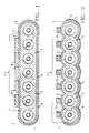
- Figure 3 shows series electrical connection between adjacent fuel cell combinations that can be used in this invention.
- the cells 1 in the vertical column shown are electrically interconnected in series, from the inner air electrode of one cell to the outer fuel electrode of the next cell through porous metal fiber felts 9. Cumulative voltage progressively increases along the cells of a column.
- air would be fed through the interior chambers 3 and gaseous fuel would be fed around the exterior of the cells and between the cells to contact the fuel electrodes 8.
- the fiber metal felts are from 80% to 97% porous, they can extend over a major portion, i.e., about 20% to 100% of the wide interconnection width 7, shown in Figures 1 and 2, fuel still being able to permeate the felts and contact the fuel electrodes.
- Figure 1 shows substantial felt coverage of the interconnection.
- the longitudinal air flow direction within channels 3 may be alternated from channel to channel within each cell combination, or be uniform within each cell combination and alternated from cell combination to cell combination. Also, alternate layers of cell combinations may be translated by 90° to permit cross-flow of the air flow channels.
- the cell stacks would be contained within an insulation package and provided with ducting for gas supplies and exhaust, and with electrical leads for power take-off.
- FIG 4 shows another variation in the electrochemical cell assembly configuration of this invention.
- air and gaseous fuel can be fed through alternate chambers, for example, gaseous fuel can be fed through additional gas feed chambers 30 formed between the plurality of cell combinations, and air through interior chambers 31 formed by the cell stack.
- air is kept contained by the dense electrolyte 5 and non-porous interconnection 6.
- Porous flexible, metal fiber felts 9 are in contact with gaseous fuel.
- the gaseous fuel is kept substantially isolated by the dense electrolyte 5 and non-porous interconnection 6.
- the wide layer of axially elongated, flexible, porous, compressible and expansible, fiber metal felt strip 9 utilized in this invention, is critical in allowing relief of thermal and mechanical stresses between ceramic portions of the cell configuration, and acts as a cushion to provide a non-monolithic structure.
Claims (7)
- Combinaison constituant une cellule électrochimique allongée axialement (1), à électrolyte oxyde solide, pour haute température, à section transversale de forme aplatie, caractérisée en ce que ladite combinaison constituant une cellule comprend une longue électrode poreuse à air (2), de section transversale aplatie, comportant une surface supérieure et de multiples chambres internes d'alimentation en gaz, parallèles à son axe longitudinal, un électrolyte oxyde solide (5) en contact avec l'électrode à air sauf sur une grande partie de la surface supérieure de l'électrode à air, une électrode externe (8) en contact avec l'électrolyte, un matériau de raccordement (6) en céramique non poreuse, conducteur d'électrons, en contact avec l'électrode à air et recouvrant de 60 à 100 % de la largeur de la section transversale de l'électrode à air non recouverte par l'électrolyte, et au moins une bande (9) de matériau collecteur de courant en fibres métalliques, poreuse, souple et conductrice d'électrons, allongée axialement, située sur le matériau de raccordement et en liaison électronique avec l'électrode à air par contact avec une grande partie du matériau de raccordement, la bande en fibres métalliques étant efficace pour relier des combinaisons supplémentaires constituant des cellules en série.
- Combinaison constituant une cellule pour haute température selon la revendication 1, caractérisée en ce que la bande souple de matériau en fibres métalliques comprend des fibres choisies parmi les fibres de nickel et les fibres de cobalt.
- Combinaison constituant une cellule pour haute température selon la revendication 1, caractérisée en ce que la combinaison constituant une cellule est une pile à combustible, les électrodes externes sont des électrodes à combustible et le matériau de la bande flexible à base de fibres métalliques est poreux à 80-97 %.
- Combinaison constituant une cellule pour haute température selon la revendication 1, caractérisée en ce que l'électrolyte est de l'oxyde de zirconium stabilisé par de l'oxyde d'yttrium, l'électrode à air est LaMnO₃ et l'électrode à combustible est choisie parmi un cermet nickel/oxyde de zirconium et un cermet cobalt/oxyde de zirconium.
- Association de plusieurs combinaisons constituant des cellules selon la revendication 1, caractérisée en ce que l'électrode externe est une électrode à combustible, le raccordement sur une structure d'électrode est relié électroniquement à une électrode à combustible d'une structure d'électrode adjacente, par la bande souple collectrice de courant en fibres métalliques, le combustible est introduit de façon à être mis en contact avec les électrodes à combustible, l'oxydant est introduit de façon à être mis en contact avec les électrodes à air, et le matériau de bande souple en fibres métalliques est efficace pour matelasser des cellules adjacentes et rendre non rigides et non fragiles les associations de cellules.
- Association de plusieurs combinaisons constituant des cellules selon la revendication 5, caractérisée en ce que l'électrode à air possède des surfaces supérieure et inférieure planes, l'air est introduit dans les chambres d'alimentation en gaz internes, et le gaz combustible est introduit autour de la partie externe des cellules de façon à être en contact avec l'électrode à combustible.
- Association de plusieurs combinaisons constituant des cellules selon la revendication 5, caractérisée en ce que des chambres d'alimentation en gaz supplémentaires sont formées entre les diverses combinaisons constituant des cellules, de l'air étant introduit dans les chambres d'alimentation en gaz internes qui sont en contact avec les électrodes à air et du gaz combustible étant introduit dans les chambres d'alimentation en gaz supplémentaires qui sont en contact avec les électrodes à combustible, et la bande en fibres métalliques forme un corps amortisseur de chocs continu entre le matériau de raccordement et des parties de l'électrode à combustible de cellules adjacentes.
Applications Claiming Priority (2)
| Application Number | Priority Date | Filing Date | Title |
|---|---|---|---|
| US07/130,927 US4874678A (en) | 1987-12-10 | 1987-12-10 | Elongated solid electrolyte cell configurations and flexible connections therefor |
| US130927 | 1987-12-10 |
Publications (2)
| Publication Number | Publication Date |
|---|---|
| EP0320087A1 EP0320087A1 (fr) | 1989-06-14 |
| EP0320087B1 true EP0320087B1 (fr) | 1992-09-09 |
Family
ID=22447026
Family Applications (1)
| Application Number | Title | Priority Date | Filing Date |
|---|---|---|---|
| EP88307054A Expired - Lifetime EP0320087B1 (fr) | 1987-12-10 | 1988-07-29 | Combinaison de cellules électrochimiques à forme allongée |
Country Status (6)
| Country | Link |
|---|---|
| US (1) | US4874678A (fr) |
| EP (1) | EP0320087B1 (fr) |
| JP (1) | JP2947557B2 (fr) |
| CA (1) | CA1318938C (fr) |
| DE (1) | DE3874498T2 (fr) |
| NO (1) | NO883432L (fr) |
Cited By (2)
| Publication number | Priority date | Publication date | Assignee | Title |
|---|---|---|---|---|
| WO2005117192A1 (fr) | 2004-05-28 | 2005-12-08 | Siemens Aktiengesellschaft | Cellule de pile a combustible a electrolyte solide a haute temperature et pile a combustible comportant ladite cellule |
| US7906250B2 (en) | 2004-09-30 | 2011-03-15 | Siemens Aktiengesellschaft | High-temperature fuel cell system and method for the production of contacting elements for such a fuel cell system |
Families Citing this family (86)
| Publication number | Priority date | Publication date | Assignee | Title |
|---|---|---|---|---|
| US5023152A (en) * | 1989-06-16 | 1991-06-11 | Osaka Gas Co., Ltd. | Fuel cell assembly |
| US5035961A (en) * | 1989-07-05 | 1991-07-30 | Combustion Engineering, Inc. | Internal cross-anchoring and reinforcing of multi-layer conductive oxides |
| EP0406523A1 (fr) * | 1989-07-07 | 1991-01-09 | Osaka Gas Co., Ltd. | Pile à combustible |
| EP0419163B1 (fr) * | 1989-09-18 | 1995-01-11 | Ngk Insulators, Ltd. | Générateur comprenant des piles à combustible |
| US5083697A (en) * | 1990-02-14 | 1992-01-28 | Difrancesco Louis | Particle-enhanced joining of metal surfaces |
| JPH03274672A (ja) * | 1990-03-26 | 1991-12-05 | Ngk Insulators Ltd | 固体電解質型燃料電池 |
| US5205990A (en) * | 1990-08-02 | 1993-04-27 | Lawless William N | Oxygen generator having honeycomb structure |
| DE59108285D1 (de) * | 1990-08-27 | 1996-11-21 | Sulzer Innotec Ag | Wärmehaushalt bei Feststoffelektrolyt-Brennstoffzellen |
| NL9002168A (nl) * | 1990-10-05 | 1992-05-06 | Blandikus Catharikus Jaspers E | Holle elektrode voor een elektrochemische cel voorzien van ten minste een toe- en een afvoeropening voor gassen, alsmede elektrochemische cel die een dergelijke elektrode omvat. |
| DE4033284A1 (de) * | 1990-10-19 | 1991-02-14 | Asea Brown Boveri | Anordnung von brennstoffzellen auf der basis eines hochtemperatur-feststoffelektrolyten |
| US5336569A (en) * | 1991-03-20 | 1994-08-09 | Ngk Insulators, Ltd. | Power generating equipment |
| US5219672A (en) * | 1991-08-12 | 1993-06-15 | Tacticon Corporation | Metal/air battery cell and assembly therefor |
| US5258240A (en) * | 1991-10-11 | 1993-11-02 | Westinghouse Electric Corp. | Solid oxide fuel cell generator |
| US5200279A (en) * | 1991-10-11 | 1993-04-06 | Westinghouse Electric Corp. | Solid oxide fuel cell generator |
| US5185220A (en) * | 1991-10-25 | 1993-02-09 | M-C Power Corporation | Fuel cell clamping force equalizer |
| US5269902A (en) * | 1992-08-20 | 1993-12-14 | Gas Research Institute, Inc. | Ion-conducting module having axially-arranged solid state electrolyte elements |
| US5366823A (en) * | 1992-12-17 | 1994-11-22 | United Technologies Corporation | Metal compression pad |
| GB9305189D0 (en) * | 1993-03-13 | 1993-04-28 | British Nuclear Fuels Plc | Fuel cells |
| JPH0737595A (ja) * | 1993-07-21 | 1995-02-07 | Fuji Electric Co Ltd | 固体電解質型燃料電池 |
| US5514296A (en) * | 1993-11-16 | 1996-05-07 | The University Of Rochester | Glassy low molar mass chiral nematic liquid crystalline compositions and optical articles formed therefrom |
| US5480738A (en) * | 1994-02-04 | 1996-01-02 | Ceramatec, Inc. | Fuel cell module |
| US5763114A (en) * | 1994-09-01 | 1998-06-09 | Gas Research Institute | Integrated reformer/CPN SOFC stack module design |
| US5612149A (en) * | 1996-01-02 | 1997-03-18 | Ceramatec, Inc. | Fuel cell column heat exchanger mated module |
| US5686198A (en) * | 1996-02-29 | 1997-11-11 | Westinghouse Electric Corporation | Low cost stable air electrode material for high temperature solid oxide electrolyte electrochemical cells |
| US5932146A (en) * | 1996-02-29 | 1999-08-03 | Siemens Westinghouse Power Corporation | Air electrode composition for solid oxide fuel cell |
| US5741605A (en) * | 1996-03-08 | 1998-04-21 | Westinghouse Electric Corporation | Solid oxide fuel cell generator with removable modular fuel cell stack configurations |
| EP0814528A3 (fr) * | 1996-06-20 | 2004-05-19 | Osaka Gas Company Limited | Empilement de piles à combustibles à électrolyte solide |
| US5756229A (en) * | 1996-12-17 | 1998-05-26 | Wilson Greatbatch Ltd. | Electrochemical cell having mechanical shock tolerance |
| AUPO724997A0 (en) * | 1997-06-10 | 1997-07-03 | Ceramic Fuel Cells Limited | A fuel cell assembly |
| US5916700A (en) * | 1998-01-23 | 1999-06-29 | Siemens Westinghouse Power Corporation | Lanthanum manganite-based air electrode for solid oxide fuel cells |
| US6326096B1 (en) | 1998-02-04 | 2001-12-04 | Gas Research Institute | Solid oxide fuel cell interconnector |
| US6217822B1 (en) | 1998-02-09 | 2001-04-17 | Siemens Westinghouse Power Corporation | Method of making straight fuel cell tubes |
| US6025083A (en) * | 1998-02-25 | 2000-02-15 | Siemens Westinghouse Power Corporation | Fuel cell generator energy dissipator |
| JP4873780B2 (ja) * | 1998-02-27 | 2012-02-08 | コーニング インコーポレイテッド | 可撓性無機電解質燃料電池構造 |
| US5993985A (en) * | 1998-04-09 | 1999-11-30 | Siemens Westinghouse Power Corporation | Fuel cell tubes and method of making same |
| US6379485B1 (en) | 1998-04-09 | 2002-04-30 | Siemens Westinghouse Power Corporation | Method of making closed end ceramic fuel cell tubes |
| US6114058A (en) * | 1998-05-26 | 2000-09-05 | Siemens Westinghouse Power Corporation | Iron aluminide alloy container for solid oxide fuel cells |
| US6054231A (en) * | 1998-07-24 | 2000-04-25 | Gas Research Institute | Solid oxide fuel cell interconnector |
| US6265095B1 (en) * | 1999-03-01 | 2001-07-24 | Sofco | Interconnect for solid oxide fuel cells |
| KR100674153B1 (ko) * | 1999-05-31 | 2007-01-24 | 자이단호징 덴료쿠추오켄큐쇼 | 평판형 고체 전해질 연료전지의 단위 셀과 이를 이용한 셀스택 |
| US6221522B1 (en) | 1999-09-10 | 2001-04-24 | Siemens Westinghouse Power Corporation | Open end protection for solid oxide fuel cells |
| US6361893B1 (en) * | 1999-11-26 | 2002-03-26 | The United States Of America As Represented By The Department Of Energy | Planar fuel cell utilizing nail current collectors for increased active surface area |
| US6423436B1 (en) * | 2000-03-30 | 2002-07-23 | The United States Of America As Represented By The United States Department Of Energy | Tubular electrochemical devices with lateral fuel aperatures for increasing active surface area |
| US6492051B1 (en) | 2000-09-01 | 2002-12-10 | Siemens Westinghouse Power Corporation | High power density solid oxide fuel cells having improved electrode-electrolyte interface modifications |
| US6416897B1 (en) | 2000-09-01 | 2002-07-09 | Siemens Westinghouse Power Corporation | Tubular screen electrical connection support for solid oxide fuel cells |
| KR20030051764A (ko) * | 2000-10-30 | 2003-06-25 | 마이클 에이. 코브 앤드 컴퍼니 | 개선된 고체 산화물 연료 셀 |
| US6953633B2 (en) * | 2002-08-06 | 2005-10-11 | General Electric Company | Fiber cooling of fuel cells |
| CA2436313A1 (fr) * | 2002-08-14 | 2004-02-14 | Hewlett-Packard Development Company, L.P. | Assemblage d'elements de pile a combustible avec elimination des tensions et methodes connexes |
| CA2414622A1 (fr) | 2002-12-17 | 2004-06-17 | Alberta Research Council Inc. | Empilement compact de piles a combustible a oxyde solide |
| DE602004030501D1 (de) * | 2003-02-28 | 2011-01-27 | Kyocera Corp | Brennstoffzelle |
| JP4021782B2 (ja) * | 2003-02-28 | 2007-12-12 | 京セラ株式会社 | 燃料電池セル |
| EP1618620A1 (fr) * | 2003-04-29 | 2006-01-25 | N.V. Bekaert S.A. | Plaque bipolaire comprenant des fibres metalliques |
| US7531261B2 (en) * | 2003-06-30 | 2009-05-12 | Corning Incorporated | Textured electrolyte sheet for solid oxide fuel cell |
| US7364812B2 (en) * | 2004-03-19 | 2008-04-29 | Pittsburgh Electric Engines, Inc. | Multi-function solid oxide fuel cell bundle and method of making the same |
| US7651801B2 (en) * | 2004-08-10 | 2010-01-26 | Siemens Energy, Inc. | Current bus and power lead assemblies for solid oxide fuel cell generators |
| DE102004047761A1 (de) * | 2004-09-30 | 2006-04-27 | Siemens Ag | Hochtemperatur-Brennstoffzellenanlage und Verfahren zur Herstellung von Kontaktierungselementen für eine derartige Brennstoffzellenanlage |
| JP4942335B2 (ja) * | 2005-11-30 | 2012-05-30 | 京セラ株式会社 | 燃料電池セルスタック並びに燃料電池 |
| KR100727684B1 (ko) * | 2005-12-08 | 2007-06-13 | 학교법인 포항공과대학교 | 고체산화물 연료전지 모듈, 이를 이용한 연료전지 및 그제작방법 |
| US20070160886A1 (en) * | 2006-01-06 | 2007-07-12 | Siemens Power Generation, Inc. | Seamless solid oxide fuel cell |
| US20070243445A1 (en) * | 2006-04-13 | 2007-10-18 | Siemens Power Generation, Inc. | High power density seal-less tubular solid oxide fuel cell by means of a wide interconnection |
| US8062798B2 (en) * | 2006-11-06 | 2011-11-22 | Siemens Energy, Inc. | Solid oxide fuel cell generator with mid-stack fuel feed |
| US8409763B2 (en) * | 2007-08-08 | 2013-04-02 | Solid Cell, Inc. | Modified planar cell (MPC) and stack based on MPC |
| US20090050680A1 (en) * | 2007-08-24 | 2009-02-26 | Protonex Technology Corporation | Method for connecting tubular solid oxide fuel cells and interconnects for same |
| US8097381B2 (en) * | 2007-09-21 | 2012-01-17 | Siemens Energy, Inc. | Solid oxide fuel cell generator including a glass sealant |
| JP5181600B2 (ja) * | 2007-09-28 | 2013-04-10 | 大日本印刷株式会社 | 固体酸化物形燃料電池、固体酸化物形燃料電池のスタック構造、及び固体酸化物形燃料電池の製造方法 |
| US20110244354A1 (en) * | 2007-09-28 | 2011-10-06 | Ines Becker | Fuel Cell System and Method for Production Thereof |
| JP2009283378A (ja) * | 2008-05-26 | 2009-12-03 | Hitachi Ltd | 固体酸化物形燃料電池管体、その成形方法およびその製造装置 |
| US8163353B2 (en) * | 2008-07-08 | 2012-04-24 | Siemens Energy, Inc. | Fabrication of copper-based anodes via atmosphoric plasma spraying techniques |
| US8097384B2 (en) * | 2008-07-08 | 2012-01-17 | Siemens Energy, Inc. | Solid oxide fuel cell with transitioned cross-section for improved anode gas management at the open end |
| DE102008049608A1 (de) * | 2008-09-30 | 2010-04-01 | Siemens Aktiengesellschaft | Verfahren zur Herstellung eines Interkonnektors für Hochtemperatur-Brennstoffzellen, zugehörige Hochtemperatur-Brennstoffzelle sowie damit aufgebaute Brennstoffzellenanlage |
| DE102008049694A1 (de) * | 2008-09-30 | 2010-04-01 | Siemens Aktiengesellschaft | Tubulare Hochtemperatur-Brennstoffzelle, damit aufgebaute Brennstoffzellenanlage und Verfahren zu deren Herstellung |
| EP2359430A1 (fr) * | 2008-12-12 | 2011-08-24 | Ezelleron GmbH | Pile à combustible à oxyde solide à géométrie de pile spéciale |
| US8173322B2 (en) | 2009-06-24 | 2012-05-08 | Siemens Energy, Inc. | Tubular solid oxide fuel cells with porous metal supports and ceramic interconnections |
| US20100325878A1 (en) * | 2009-06-24 | 2010-12-30 | Gong Zhang | Bi Containing Solid Oxide Fuel Cell System With Improved Performance and Reduced Manufacturing Costs |
| US8163433B2 (en) * | 2009-08-19 | 2012-04-24 | Siemens Energy, Inc. | Fuel cell integral bundle assembly including ceramic open end seal and vertical and horizontal thermal expansion control |
| US8460838B2 (en) * | 2009-08-19 | 2013-06-11 | Siemens Energy, Inc. | Generator module architecture for a large solid oxide fuel cell power plant |
| JP4901996B2 (ja) * | 2010-02-22 | 2012-03-21 | 日本碍子株式会社 | 燃料電池セル |
| JP4881479B2 (ja) * | 2010-03-26 | 2012-02-22 | 日本碍子株式会社 | 燃料電池セル |
| KR101188672B1 (ko) | 2010-12-28 | 2012-10-08 | 포항공과대학교 산학협력단 | 고체산화물 연료전지용 일체형 단위셀 및 단일구조체 스택과 그 제작 방법 |
| JP5116181B1 (ja) * | 2011-10-14 | 2013-01-09 | 日本碍子株式会社 | 燃料電池のスタック構造体 |
| JP4942852B2 (ja) * | 2011-10-24 | 2012-05-30 | 京セラ株式会社 | 燃料電池セルスタック並びに燃料電池 |
| JP6055243B2 (ja) * | 2012-09-04 | 2016-12-27 | 日本碍子株式会社 | グリーン接合体の製造方法 |
| JP5646779B2 (ja) * | 2013-04-19 | 2014-12-24 | 日本碍子株式会社 | 燃料電池 |
| EP3152794A4 (fr) * | 2014-06-05 | 2017-12-20 | Saint-Gobain Ceramics and Plastics, Inc. | Pile à combustible ayant une anode tubulaire plate |
| CN106299430B (zh) * | 2015-05-28 | 2018-10-02 | 清华大学 | 燃料电池的使用方法 |
| WO2018042478A1 (fr) * | 2016-08-29 | 2018-03-08 | FCO Power株式会社 | Pile à combustible à oxyde solide et son procédé de fabrication |
Family Cites Families (17)
| Publication number | Priority date | Publication date | Assignee | Title |
|---|---|---|---|---|
| US3206334A (en) * | 1965-02-15 | 1965-09-14 | Prototech Inc | Catalytic and electrochemical cell structures |
| DE1571966A1 (de) * | 1965-10-08 | 1971-04-08 | Battelle Institut E V | Aggregat galvanischer Brennstoffzellen fuer hohe Temperaturen |
| US3895960A (en) * | 1970-08-27 | 1975-07-22 | Westinghouse Electric Corp | Diffusion-bonded battery electrode plaques |
| US3702019A (en) * | 1971-04-13 | 1972-11-07 | Westinghouse Electric Corp | Method of making diffusion bonded battery plaques |
| US3835514A (en) * | 1971-05-17 | 1974-09-17 | Westinghouse Electric Corp | Method of making laminated diffusion bonded battery plaques |
| AU545997B2 (en) * | 1980-12-22 | 1985-08-08 | Westinghouse Electric Corporation | High temp solid electrolyte fuel cell |
| ZA814990B (en) * | 1980-12-22 | 1982-11-24 | Westinghouse Electric Corp | Fuel cell generator |
| US4490444A (en) * | 1980-12-22 | 1984-12-25 | Westinghouse Electric Corp. | High temperature solid electrolyte fuel cell configurations and interconnections |
| US4395468A (en) * | 1980-12-22 | 1983-07-26 | Westinghouse Electric Corp. | Fuel cell generator |
| US4431715A (en) * | 1982-03-24 | 1984-02-14 | Westinghouse Electric Corp. | Electrical contact structures for solid oxide electrolyte fuel cell |
| US4499663A (en) * | 1983-10-12 | 1985-02-19 | The United States Of America As Represented By The United States Department Of Energy | Method of fabricating a monolithic core for a solid oxide fuel cell |
| US4476198A (en) * | 1983-10-12 | 1984-10-09 | The United States Of America As Represented By The United States Department Of Energy | Solid oxide fuel cell having monolithic core |
| US4664987A (en) * | 1984-11-15 | 1987-05-12 | Westinghouse Electric Corp. | Fuel cell arrangement |
| US4748091A (en) * | 1985-03-21 | 1988-05-31 | Westinghouse Electric Corp. | Bipolar plating of metal contacts onto oxide interconnection for solid oxide electrochemical cell |
| US4725346A (en) * | 1986-07-25 | 1988-02-16 | Ceramatec, Inc. | Electrolyte assembly for oxygen generating device and electrodes therefor |
| US4751152A (en) * | 1987-04-06 | 1988-06-14 | Westinghouse Electric Corp. | High bulk self-supporting electrode with integral gas feed conduit for solid oxide fuel cells |
| CA1302486C (fr) * | 1987-04-06 | 1992-06-02 | Philip Reichner | Electrode autostable a faible gradient de tension circonferentielle pour piles a combustible oxyde solide |
-
1987
- 1987-12-10 US US07/130,927 patent/US4874678A/en not_active Expired - Lifetime
-
1988
- 1988-07-29 DE DE8888307054T patent/DE3874498T2/de not_active Expired - Lifetime
- 1988-07-29 EP EP88307054A patent/EP0320087B1/fr not_active Expired - Lifetime
- 1988-08-03 NO NO88883432A patent/NO883432L/no unknown
- 1988-08-16 CA CA000574889A patent/CA1318938C/fr not_active Expired - Lifetime
- 1988-10-06 JP JP63252879A patent/JP2947557B2/ja not_active Expired - Lifetime
Cited By (2)
| Publication number | Priority date | Publication date | Assignee | Title |
|---|---|---|---|---|
| WO2005117192A1 (fr) | 2004-05-28 | 2005-12-08 | Siemens Aktiengesellschaft | Cellule de pile a combustible a electrolyte solide a haute temperature et pile a combustible comportant ladite cellule |
| US7906250B2 (en) | 2004-09-30 | 2011-03-15 | Siemens Aktiengesellschaft | High-temperature fuel cell system and method for the production of contacting elements for such a fuel cell system |
Also Published As
| Publication number | Publication date |
|---|---|
| DE3874498T2 (de) | 1993-03-11 |
| DE3874498D1 (de) | 1992-10-15 |
| NO883432D0 (no) | 1988-08-03 |
| JPH01169878A (ja) | 1989-07-05 |
| JP2947557B2 (ja) | 1999-09-13 |
| EP0320087A1 (fr) | 1989-06-14 |
| NO883432L (no) | 1989-06-12 |
| CA1318938C (fr) | 1993-06-08 |
| US4874678A (en) | 1989-10-17 |
Similar Documents
| Publication | Publication Date | Title |
|---|---|---|
| EP0320087B1 (fr) | Combinaison de cellules électrochimiques à forme allongée | |
| US4791035A (en) | Cell and current collector felt arrangement for solid oxide electrochemical cell combinations | |
| US4888254A (en) | Low circumferential voltage gradient self supporting electrode for solid oxide fuel cells | |
| CA1301243C (fr) | Electrode autoportante a canaux d'alimentation en gaz incorpores pour piles a combustible a oxyde solide | |
| US4476196A (en) | Solid oxide fuel cell having monolithic cross flow core and manifolding | |
| EP0264688B1 (fr) | Générateur de piles à combustible comportant des cellules à combustible autoportentes à électrolyte d'oxydes solides présentant un écoulement de gaz élevé | |
| US4476197A (en) | Integral manifolding structure for fuel cell core having parallel gas flow | |
| EP1122806B1 (fr) | Pile à combustible à oxydes solides | |
| US3460991A (en) | Fuel cell with tubular electrodes and solid electrolyte | |
| US5273838A (en) | Double interconnection fuel cell array | |
| EP0285727B1 (fr) | Electrodes autoportantes pour cellules à combustible à oxydes solides | |
| US5882809A (en) | Solid oxide fuel cell with multi-unit construction and prismatic design | |
| GB2175736A (en) | Serially connected solid oxide fuel cells having a monolithic cores | |
| JPH0159705B2 (fr) | ||
| EP0505184A1 (fr) | Dispositif générateur de courant électrique comportant des piles à combustible à oxydes solides | |
| US6096451A (en) | Solid-electrolyte fuel cell | |
| US5372895A (en) | Solid oxide fuel cell and method for manufacturing the same | |
| EP0536909B1 (fr) | Générateur de cellules à combustible à oxydes solides | |
| JPH046752A (ja) | 固体電解質燃料電池 | |
| JP2933228B2 (ja) | 固体電解質型燃料電池モジュール | |
| JP2780885B2 (ja) | 固体電解質燃料電池 | |
| JPH0794191A (ja) | 高温固体酸化物電解質電気化学的電池の空気電極 | |
| JP2783926B2 (ja) | 固体電解質型燃料電池の単電池及びこれを用いた発電装置 | |
| US4873156A (en) | Solid electrolytic fuel cell and method for manufacturing same | |
| JP5300199B2 (ja) | 燃料電池 |
Legal Events
| Date | Code | Title | Description |
|---|---|---|---|
| PUAI | Public reference made under article 153(3) epc to a published international application that has entered the european phase |
Free format text: ORIGINAL CODE: 0009012 |
|
| AK | Designated contracting states |
Kind code of ref document: A1 Designated state(s): BE DE FR GB IT NL SE |
|
| 17P | Request for examination filed |
Effective date: 19891207 |
|
| 17Q | First examination report despatched |
Effective date: 19910506 |
|
| GRAA | (expected) grant |
Free format text: ORIGINAL CODE: 0009210 |
|
| AK | Designated contracting states |
Kind code of ref document: B1 Designated state(s): BE DE FR GB IT NL SE |
|
| REF | Corresponds to: |
Ref document number: 3874498 Country of ref document: DE Date of ref document: 19921015 |
|
| ITF | It: translation for a ep patent filed |
Owner name: MODIANO & ASSOCIATI S.R |
|
| ET | Fr: translation filed | ||
| PLBE | No opposition filed within time limit |
Free format text: ORIGINAL CODE: 0009261 |
|
| STAA | Information on the status of an ep patent application or granted ep patent |
Free format text: STATUS: NO OPPOSITION FILED WITHIN TIME LIMIT |
|
| 26N | No opposition filed | ||
| EAL | Se: european patent in force in sweden |
Ref document number: 88307054.2 |
|
| PGFP | Annual fee paid to national office [announced via postgrant information from national office to epo] |
Ref country code: SE Payment date: 19990708 Year of fee payment: 12 |
|
| PGFP | Annual fee paid to national office [announced via postgrant information from national office to epo] |
Ref country code: BE Payment date: 19990713 Year of fee payment: 12 |
|
| PGFP | Annual fee paid to national office [announced via postgrant information from national office to epo] |
Ref country code: NL Payment date: 19990719 Year of fee payment: 12 |
|
| PG25 | Lapsed in a contracting state [announced via postgrant information from national office to epo] |
Ref country code: SE Free format text: LAPSE BECAUSE OF NON-PAYMENT OF DUE FEES Effective date: 20000730 |
|
| PG25 | Lapsed in a contracting state [announced via postgrant information from national office to epo] |
Ref country code: BE Free format text: LAPSE BECAUSE OF NON-PAYMENT OF DUE FEES Effective date: 20000731 |
|
| BERE | Be: lapsed |
Owner name: WESTINGHOUSE ELECTRIC CORP. Effective date: 20000731 |
|
| PG25 | Lapsed in a contracting state [announced via postgrant information from national office to epo] |
Ref country code: NL Free format text: LAPSE BECAUSE OF NON-PAYMENT OF DUE FEES Effective date: 20010201 |
|
| EUG | Se: european patent has lapsed |
Ref document number: 88307054.2 |
|
| NLV4 | Nl: lapsed or anulled due to non-payment of the annual fee |
Effective date: 20010201 |
|
| REG | Reference to a national code |
Ref country code: GB Ref legal event code: IF02 |
|
| PGFP | Annual fee paid to national office [announced via postgrant information from national office to epo] |
Ref country code: DE Payment date: 20070919 Year of fee payment: 20 |
|
| PGFP | Annual fee paid to national office [announced via postgrant information from national office to epo] |
Ref country code: GB Payment date: 20070710 Year of fee payment: 20 |
|
| PGFP | Annual fee paid to national office [announced via postgrant information from national office to epo] |
Ref country code: IT Payment date: 20070726 Year of fee payment: 20 |
|
| PGFP | Annual fee paid to national office [announced via postgrant information from national office to epo] |
Ref country code: FR Payment date: 20070720 Year of fee payment: 20 |
|
| REG | Reference to a national code |
Ref country code: GB Ref legal event code: PE20 Expiry date: 20080728 |
|
| PG25 | Lapsed in a contracting state [announced via postgrant information from national office to epo] |
Ref country code: GB Free format text: LAPSE BECAUSE OF EXPIRATION OF PROTECTION Effective date: 20080728 |