EP0316849B1 - Cleaning head - Google Patents
Cleaning head Download PDFInfo
- Publication number
- EP0316849B1 EP0316849B1 EP88118966A EP88118966A EP0316849B1 EP 0316849 B1 EP0316849 B1 EP 0316849B1 EP 88118966 A EP88118966 A EP 88118966A EP 88118966 A EP88118966 A EP 88118966A EP 0316849 B1 EP0316849 B1 EP 0316849B1
- Authority
- EP
- European Patent Office
- Prior art keywords
- open mouth
- chamber
- liquid
- inner compartment
- cleaning head
- Prior art date
- Legal status (The legal status is an assumption and is not a legal conclusion. Google has not performed a legal analysis and makes no representation as to the accuracy of the status listed.)
- Expired - Lifetime
Links
- 238000004140 cleaning Methods 0.000 title claims abstract description 45
- 239000007788 liquid Substances 0.000 claims abstract description 50
- 230000002706 hydrostatic effect Effects 0.000 claims abstract description 4
- 238000003860 storage Methods 0.000 claims abstract description 3
- 238000011065 in-situ storage Methods 0.000 claims description 2
- 239000004744 fabric Substances 0.000 description 3
- 239000003599 detergent Substances 0.000 description 2
- 238000004891 communication Methods 0.000 description 1
- 238000010276 construction Methods 0.000 description 1
- 238000005187 foaming Methods 0.000 description 1
- 238000000034 method Methods 0.000 description 1
- 238000005507 spraying Methods 0.000 description 1
- 238000003809 water extraction Methods 0.000 description 1
- 238000009736 wetting Methods 0.000 description 1
Images

Classifications
-
- A—HUMAN NECESSITIES
- A47—FURNITURE; DOMESTIC ARTICLES OR APPLIANCES; COFFEE MILLS; SPICE MILLS; SUCTION CLEANERS IN GENERAL
- A47L—DOMESTIC WASHING OR CLEANING; SUCTION CLEANERS IN GENERAL
- A47L9/00—Details or accessories of suction cleaners, e.g. mechanical means for controlling the suction or for effecting pulsating action; Storing devices specially adapted to suction cleaners or parts thereof; Carrying-vehicles specially adapted for suction cleaners
- A47L9/02—Nozzles
-
- A—HUMAN NECESSITIES
- A47—FURNITURE; DOMESTIC ARTICLES OR APPLIANCES; COFFEE MILLS; SPICE MILLS; SUCTION CLEANERS IN GENERAL
- A47L—DOMESTIC WASHING OR CLEANING; SUCTION CLEANERS IN GENERAL
- A47L11/00—Machines for cleaning floors, carpets, furniture, walls, or wall coverings
- A47L11/40—Parts or details of machines not provided for in groups A47L11/02 - A47L11/38, or not restricted to one of these groups, e.g. handles, arrangements of switches, skirts, buffers, levers
- A47L11/4036—Parts or details of the surface treating tools
- A47L11/4044—Vacuuming or pick-up tools; Squeegees
-
- A—HUMAN NECESSITIES
- A47—FURNITURE; DOMESTIC ARTICLES OR APPLIANCES; COFFEE MILLS; SPICE MILLS; SUCTION CLEANERS IN GENERAL
- A47L—DOMESTIC WASHING OR CLEANING; SUCTION CLEANERS IN GENERAL
- A47L11/00—Machines for cleaning floors, carpets, furniture, walls, or wall coverings
- A47L11/29—Floor-scrubbing machines characterised by means for taking-up dirty liquid
- A47L11/30—Floor-scrubbing machines characterised by means for taking-up dirty liquid by suction
-
- A—HUMAN NECESSITIES
- A47—FURNITURE; DOMESTIC ARTICLES OR APPLIANCES; COFFEE MILLS; SPICE MILLS; SUCTION CLEANERS IN GENERAL
- A47L—DOMESTIC WASHING OR CLEANING; SUCTION CLEANERS IN GENERAL
- A47L11/00—Machines for cleaning floors, carpets, furniture, walls, or wall coverings
- A47L11/34—Machines for treating carpets in position by liquid, foam, or vapour, e.g. by steam
-
- A—HUMAN NECESSITIES
- A47—FURNITURE; DOMESTIC ARTICLES OR APPLIANCES; COFFEE MILLS; SPICE MILLS; SUCTION CLEANERS IN GENERAL
- A47L—DOMESTIC WASHING OR CLEANING; SUCTION CLEANERS IN GENERAL
- A47L11/00—Machines for cleaning floors, carpets, furniture, walls, or wall coverings
- A47L11/40—Parts or details of machines not provided for in groups A47L11/02 - A47L11/38, or not restricted to one of these groups, e.g. handles, arrangements of switches, skirts, buffers, levers
- A47L11/408—Means for supplying cleaning or surface treating agents
- A47L11/4088—Supply pumps; Spraying devices; Supply conduits
Definitions
- This invention relates to a cleaning head for use with an apparatus for cleaning floors, walls, carpets, curtains, upholstery and the like, and more particularly concerns a cleaning head for use in the process of water extraction cleaning, in which a carpet or the like is thoroughly wetted by a solution containing a suitable cleansing agent, such as a non-foaming detergent, and the carpet or the like is then dried by the uptake of that solution by means of suction.
- a cleaning head is the subject of our British Patent No. 1601455 and the present invention concerns a development of the design disclosed therein.
- GB 1601455 illustrates the basic form of cleaning head to which the present invention is applied and comprises a suction chamber having an open mouth and a centrally disposed outlet for connection to a source of suction, and an inner compartment extending medially within the suction chamber and having a side wall defining an open mouth substantially in the plane of the open mouth of the suction chamber, the inner compartment having associated therewith cleaning liquid distributing means including a plurality of closely spaced fine outlet passageways adapted to allow cleaning liquid to flow into the inner compartment at a position spaced from the mouth thereof.
- an elongate cleaning head comprising a suction chamber having an open mouth and a centrally disposed outlet for connection to a source of suction, and an inner compartment extending substantially medially within the suction chamber and having side walls defining an open mouth substantially in the plane of the open mouth of the suction chamber, the inner compartment having associated therewith a cleaning liquid distributing chamber formed with a plurality of closely spaced fine outlet passageways adapted to allow cleaning liquid to flow into the inner compartment at a position spaced from the mouth thereof, wherein the suction chamber is divided externally of the inner compartment into two laterally spaced suction zones by means of a central baffle which diverges in a direction away from the open mouth of the suction chamber towards an upper zone of the suction chamber into which upper zone said outlet opens.
- the divided suction chamber with the upwardly divergent baffle causes the air flow through the head from the open mouth to the outlet to be split into two streams which diverge away from the centre of the head in the respective suction zones and then converge towards the outlet in the upper zone of the head.
- This arrangement makes it possible to increase the transverse width of the head without reducing the efficiency of the liquid pick-up operation and without increasing the overall air flow requirement.
- the use of a cleaning head in accordance with the present invention typically makes it possible to utilise a cleaning head having a width of approximately 20cm (8 inches) without increasing the air flow requirement over that which would otherwise be required for a 12.5cm (5 inch) head whilst maintaining equivalent efficiency of operation.
- the inner compartment is formed or provided with a separating wall dividing it into an outer liquid delivery chamber adjacent to said open mouth of the inner compartment and an inner chamber which serves as said liquid distributing chamber, said outlet passageways being formed in said separating wall.
- said liquid distribution chamber is so dimensioned to serve as a storage reservoir within the cleaning head, for the cleaning liquid, which reservoir has a height sufficient to create a substantially equal hydrostatic head pressure at each of the outlet passageways.
- the height of the reservoir may be at least 10 mm.
- said liquid distribution chamber has sufficient volume such that when substantially full a substantially equal flow rate of cleaning liquid from each of the outlet passageways can be achieved during application of the open mouth to a surface.
- the volume may be approximately 1cc per linear centimetre of the head.
- the open mouth of the inner compartment is preferably of elongate configuration and said inner compartment preferably extends across the suction chamber substantially parallel to the main axis thereof.
- the open mouth of said inner compartment is preferably located substantially centrally within the open mouth of the suction chamber whereby air-flow into the suction chamber takes place on both sides of the open mouth of the inner compartment, and the upper side of the body is preferably spaced above the upper side of the inner compartment by such a distance as to allow substantially unrestricted air-flow towards the outlet from both sides of the inner compartment.
- said inner compartment may be formed as a separate unit which is removable from the suction chamber, although it may alternatively be formed integrally.
- the present invention further resides in an inner housing for assembly with a suction cleaning head of the kind comprising a suction chamber having an open mouth and a centrally disposed outlet for connection to a source of suction, the inner housing comprising an elongate body dimensioned for reception medially within said suction chamber and affording an open mouth which when the inner housing is in situ is subtantially in the plane of the open mouth of the suction chamber the housing being formed or provided with a separating wall dividing it into an outer liquid delivery chamber adjacent to said open mouth and an inner liquid distributing chamber having a liquid inlet, said separating wall being formed with a plurality of fine outlet passageways at closely spaced intervals along the length thereof to allow liquid to flow from said liquid distributing chamber into said liquid delivery chamber at a position spaced from the open mouth, characterised in that externally the inner housing is formed or provided with baffles on opposite sides thereof, each comprising a rib of shallow V-shape with two wings diverging in a direction away from the open mouth of the housing.
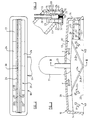
- the first embodiment of cleaning head in accordance with the invention as illustrated in Figures 1 to 3 comprises an elongate outer housing 10 with a centrally disposed tubular outlet spigot 11 for attachment to the suction hose (not shown).
- the outer housing 10 receives therein a structurally separate medially extending inner housing 20 having side walls 22 which are spaced from the side walls 12 of the outer housing and an upper wall 23 which is spaced from the upper wall 13 of the outer housing.
- the side walls 22 of the inner housing 20 each carry a shallow V-formation rib 24 including wings 24 a , 24 b which bridge the space between the side walls 22 of the inner housing and the side walls 12 of the outer housing.
- the wings 24 a , 24 b diverge upwardly away from the open mouth 15 of the outer housing and outwardly from the centre.
- the ribs 24 serve as baffles whereby the suction chamber defined by the outer housing 10 is divided into two laterally spaced suction zones 16 a , 16 b in which air drawn in through the open mouth 15 is divided into two divergent streams as indicated by the arrows A and B.
- the ribs 24 terminate at positions approximately half way between the centre line and the end walls 14 of the outer housing, so that the air flows enter an upper zone 17 of the outer housing above the inner housing 20 and converge towards the outlet spigot 11 as indicated by arrows C.
- the portion of the inner housing 20 adjacent to the open mouth 25 accommodates a T-section bar member 30 whereof the transverse web 32 is received innermost and is supported at the ends of the inner compartment 20 by engagement within recessed portions of the end walls thereof.
- the central leg 31 of the T-section bar member 30 extends downwardly from the web 32 and terminates in the plane of the open mouth 25 of the inner compartment 20.
- the lateral edges of the transverse web 32 of the T-section bar member 30 are formed with a plurality of spaced calibrated grooves 33 which extend between each face thereof.
- the transverse web 32 of the T-section bar member 30 forms a separating wall which divides the inner compartment 20 into an internal liquid distribution chamber 26 above the transverse web 32 and an outer liquid delivery chamber 29 below the transverse web 32, between which chambers communication is provided through the grooves 33.
- the chamber 26 within the inner housing above the bar 30 has a volume such that it servces as a reservoir for the reception of a cleaning solution which is supplied through a pipe (not shown) to an inlet spigot 21 which protrudes from the inner housing as shown in Figures 1 and 3, whereby when substantially full there is a substantially equal rate of delivery from each passageway 33 under equal hydrostatic pressure.
- the calibrated grooves 33 are provided at spaced intervals along substantially the entire length of the edges of the web 32 to regulate the flow of liquid so as to cause it to be delivered uniformly and continuously at an appropriate rate.
- the apertures 33 have a width of about 0.5 mm and are spaced on 10mm centres.
- the cleaning solution may be supplied by any appropriate means to the chamber 26, which may typically have a height of at least 1cm and a volume of about 1cc per centimetre of its length.
- the head illustrated in Figures 1 to 3 is designed for use with substantially non-pressurised liquid delivery systems.
- the liquid may be supplied gravitationally, or by a syphon system, in either case optionally assisted by a slight positive pressure generated for example by the application of exhaust air from the suction cleaner fan to a liquid reservoir in the manner disclosed in our British patent No. 1601456.
- the space within the inner housing below the transverse flange 32 of the bar 30 defines the liquid delivery chamber 29 which extends medially of the outer housing 10.
- the arrangement of the end faces of the side walls 22 in the same plane as the mouth of the outer housing 10 ensures that such inner compartment is substantially sealed against the fabric being treated and that there is virtually no possibility of the liquid passing through the grooves 33 being drawn away directly by virtue of the air flow established within the head. Instead, the liquid is shielded by the side walls 22 and is constrained by the side walls to flow onto the fabric being cleaned. In this way, a thorough wetting of the fabric is ensured without spraying. This in turn makes it possible for the appliance to operate with only a low pressure gradient acting on the liquid, and without the need for any pump for the delivery of cleaning liquid to the head under substantial pressure.
- the divided air flow resulting from the ribs 24 ensures that substantially uniform suction is applied over the entire length of the head, which can thus be made sigificantly greater than in the absence of such ribs without requiring an increase in the overall air flow and without employing a correspondingly more powerful motor to drive the fan of the suction cleaner.
- the space above and around the inner housing 20 is such as to provide substantially unimpeded air-flow through the suction chamber on both sides of the inner housing, and over the top thereof into the upper zone 17 of the outer housing 10 and thence to the outlet 11.
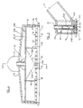
- the outer housing 10A of the second embodiment is somewhat deeper than theat of the first embodiment and the inner housing 20A is also deeper than that of the first embodiment with a flat upper wall 23A.
- the modified inner housing 20A as illustrated in Figures 6 to 10 is generally similar in construction to the inner housing 20 previously described, except in the following respects.
- the wings 24 a , 24 b of the shallow V-shape ribs 24 do not extend directly to the lower edge of the inner housing, but an additional, vertical wing 24 c extends downwardly from the point at which the wings 24 a , 24 b meet and terminates at the lower edge of the housing 20A.
- Internal ribs 22 a are formed on the side walls of the housing 20A and terminate as shown at positions spaced inwardly from the open mouth of the housing.
- the ribs 22 a serve to locate the T-section bar 30 within the housing 20A.
- the calibrated air-flow passageway in the illustrated embodiments comprises a pair of small apertures 28 which extend through the upper wall of the inner compartment and open into the upper region of the suction chamber 11, other arrangements are possible. For example there may be a single opening in the upper region of the side wall 22 of the inner compartment 20 in register with the opening afforded by the outlet 14, or a tube may extend from the inner compartment into and along the length of the outlet 14.
- the inner housing may be formed as a set of modules which can be interengaged in end-to-end relationship and to be receivable within suction heads of a variety of dimensions as required.
- a conventional suction head may be adapted for use for wet cleaning of floor surfaces.
- V-formation rib 24 is formed on each side of the inner housing in a central region thereof, it may be appropriate to provide additional V-formation ribs at positions offset from the central region towards the ends of the housing, particularly for heads of increased width.
Landscapes
- Engineering & Computer Science (AREA)
- Mechanical Engineering (AREA)
- Nozzles For Electric Vacuum Cleaners (AREA)
- Cleaning By Liquid Or Steam (AREA)
- Cleaning In General (AREA)
- Supporting Of Heads In Record-Carrier Devices (AREA)
- Treatment Of Fiber Materials (AREA)
- Valve Device For Special Equipments (AREA)
- Jet Pumps And Other Pumps (AREA)
- Cleaning Or Drying Semiconductors (AREA)
- Die Bonding (AREA)
- Supply And Installment Of Electrical Components (AREA)
- Automatic Analysis And Handling Materials Therefor (AREA)
- Cleaning Implements For Floors, Carpets, Furniture, Walls, And The Like (AREA)
- Chair Legs, Seat Parts, And Backrests (AREA)
- Window Of Vehicle (AREA)
- Detergent Compositions (AREA)
- Harvester Elements (AREA)
- Sheets, Magazines, And Separation Thereof (AREA)
- Gas Separation By Absorption (AREA)
Priority Applications (2)
| Application Number | Priority Date | Filing Date | Title |
|---|---|---|---|
| EP88118966A EP0316849B1 (en) | 1987-11-18 | 1988-11-14 | Cleaning head |
| AT88118966T ATE81956T1 (de) | 1987-11-18 | 1988-11-14 | Reinigungskopf. |
Applications Claiming Priority (5)
| Application Number | Priority Date | Filing Date | Title |
|---|---|---|---|
| AUPI549687 | 1987-11-18 | ||
| AU5496/87 | 1987-11-18 | ||
| AUPI641388 | 1988-01-22 | ||
| AU6413/88 | 1988-01-22 | ||
| EP88118966A EP0316849B1 (en) | 1987-11-18 | 1988-11-14 | Cleaning head |
Publications (3)
| Publication Number | Publication Date |
|---|---|
| EP0316849A2 EP0316849A2 (en) | 1989-05-24 |
| EP0316849A3 EP0316849A3 (en) | 1989-12-27 |
| EP0316849B1 true EP0316849B1 (en) | 1992-11-04 |
Family
ID=25643384
Family Applications (3)
| Application Number | Title | Priority Date | Filing Date |
|---|---|---|---|
| EP88118966A Expired - Lifetime EP0316849B1 (en) | 1987-11-18 | 1988-11-14 | Cleaning head |
| EP88118964A Expired - Lifetime EP0316848B1 (en) | 1987-11-18 | 1988-11-14 | Suction cleaning head |
| EP19910120401 Withdrawn EP0478007A3 (en) | 1987-11-18 | 1988-11-14 | Suction cleaning head |
Family Applications After (2)
| Application Number | Title | Priority Date | Filing Date |
|---|---|---|---|
| EP88118964A Expired - Lifetime EP0316848B1 (en) | 1987-11-18 | 1988-11-14 | Suction cleaning head |
| EP19910120401 Withdrawn EP0478007A3 (en) | 1987-11-18 | 1988-11-14 | Suction cleaning head |
Country Status (16)
| Country | Link |
|---|---|
| US (2) | US5105503A (enExample) |
| EP (3) | EP0316849B1 (enExample) |
| JP (2) | JPH03500727A (enExample) |
| KR (1) | KR960001797B1 (enExample) |
| AT (2) | ATE81956T1 (enExample) |
| BR (2) | BR8807804A (enExample) |
| CA (2) | CA1324464C (enExample) |
| DE (2) | DE3875698T2 (enExample) |
| DK (2) | DK170791B1 (enExample) |
| ES (2) | ES2035222T3 (enExample) |
| GR (2) | GR3006295T3 (enExample) |
| IE (2) | IE63287B1 (enExample) |
| MX (2) | MX170208B (enExample) |
| MY (2) | MY103472A (enExample) |
| PT (2) | PT89023B (enExample) |
| WO (2) | WO1989004627A1 (enExample) |
Families Citing this family (27)
| Publication number | Priority date | Publication date | Assignee | Title |
|---|---|---|---|---|
| GB8822391D0 (en) * | 1988-09-23 | 1988-10-26 | Vax Appliances Ltd | Cleaning head |
| DE4014085C1 (en) * | 1990-05-02 | 1991-11-21 | Alfred Kaercher Gmbh & Co, 7057 Winnenden, De | Cleaner head for high pressure cleaning of hard surface - has fluid feed and off-take to carry dirt etc. and covered area for closed area against hard surface |
| GB9020850D0 (en) * | 1990-09-25 | 1990-11-07 | Vax Appliances Ltd | Apparatus for cleaning floors,carpets and the like |
| RU2062602C1 (ru) * | 1990-10-02 | 1996-06-27 | Вэкс Эплайенсиз Лимитед | Всасывающая чистящая насадка |
| US5483726A (en) * | 1993-01-04 | 1996-01-16 | Bissell Inc. | Combination vacuum cleaner and water extractor power foot |
| BE1007489A3 (nl) * | 1993-09-10 | 1995-07-11 | Philips Electronics Nv | Zuighulpstuk, alsmede sproeiorgaan geschikt voor toepassing in een dergelijk zuighulpstuk en stofzuiger voorzien van een dergelijk zuighulpstuk. |
| US5867861A (en) * | 1995-11-13 | 1999-02-09 | Kasen; Timothy E. | Upright water extraction cleaning machine with two suction nozzles |
| US5600866A (en) * | 1995-12-12 | 1997-02-11 | Shop Vac Corporation | Cleaning fluid tank assembly |
| DE19651693C2 (de) * | 1996-12-12 | 1999-09-30 | Dornier Tech Gmbh & Co | Automatische Scheibenreinigungsanlage |
| KR101029799B1 (ko) * | 2003-08-18 | 2011-04-18 | 엘지전자 주식회사 | 물청소 겸용 진공청소기의 노즐 어셈블리 |
| US6981338B2 (en) * | 2003-12-23 | 2006-01-03 | Jensen Dale S | Device for improved removal of liquid from fabric |
| US20080184520A1 (en) * | 2006-09-14 | 2008-08-07 | Wolfe Kevin A | Self-propelled extraction systems and methods |
| US8510902B2 (en) * | 2007-12-03 | 2013-08-20 | Dri-Eaz Products, Inc. | Air induction hard surface cleaning tool with an internal baffle |
| US8365346B2 (en) * | 2008-12-15 | 2013-02-05 | Ecotech Service Co., Llc | Multi-purpose vacuum unit |
| DE102009011433A1 (de) | 2009-02-20 | 2010-09-02 | Kärcher Futuretech GmbH | Sprühextraktionsdüse zum Reinigen einer Oberfläche, insbesondere zum Dekontaminieren der Oberfläche |
| US8261407B2 (en) * | 2009-09-01 | 2012-09-11 | Techtronic Floor Care Technology Limited | Vacuum cleaner accessory tool |
| PL2329754T3 (pl) * | 2009-12-03 | 2014-01-31 | Bissell Homecare Inc | Głębokie odkurzanie piorące z małą ilością wilgoci |
| EP2385339A1 (en) * | 2010-05-05 | 2011-11-09 | Leica Geosystems AG | Surface sensing device with optical monitoring system |
| US9107557B2 (en) | 2011-03-14 | 2015-08-18 | Roy Studebaker | Rotary surface cleaning tool |
| US9402523B2 (en) | 2011-03-14 | 2016-08-02 | Roy Studebaker | Rotary surface cleaning tool |
| USD684737S1 (en) | 2011-08-31 | 2013-06-18 | Dri-Eaz Products, Inc. | Extractor housing |
| US9195238B2 (en) | 2012-06-15 | 2015-11-24 | Sapphire Scientific, Inc. | Waste water vessels with multiple valved chambers, and associated systems and methods |
| USD701661S1 (en) | 2012-09-04 | 2014-03-25 | Dri-Eaz Products, Inc. | Extractor port housing |
| US9351622B2 (en) * | 2012-09-04 | 2016-05-31 | Sapphire Scientific Inc. | Fluid extracting device with shaped head and associated systems and methods of use and manufacture |
| US10584497B2 (en) | 2014-12-05 | 2020-03-10 | Dri-Eaz Products, Inc. | Roof cleaning processes and associated systems |
| US10060641B2 (en) | 2015-02-25 | 2018-08-28 | Dri-Eaz Products, Inc. | Systems and methods for drying roofs |
| US10264939B2 (en) | 2015-08-17 | 2019-04-23 | Skagit Northwest Holdings, Inc. | Rotary surface cleaning tool |
Family Cites Families (15)
| Publication number | Priority date | Publication date | Assignee | Title |
|---|---|---|---|---|
| GB845991A (en) * | 1956-07-30 | 1960-08-24 | Atomic Energy Authority Uk | Improvements in or relating to washing devices |
| AT283655B (de) * | 1966-09-12 | 1970-08-10 | Egon Nohl | Vorrichtung zum Auftragen und Wiederabsaugen von flüssigen Reinigungs- oder Pflegemitteln in Schaumform |
| GB1121225A (en) | 1966-11-25 | 1968-07-24 | Wladyslaw Brycki | Improvements in or relating to suction cleaning apparatus |
| GB1291138A (en) | 1970-03-25 | 1972-09-27 | Wladyslaw Brycki | Improvements in or relating to suction cleaning apparatus |
| US3747155A (en) * | 1971-07-09 | 1973-07-24 | G Koellisch | Nozzle construction for portable carpet cleaning machine |
| CA1120215A (en) * | 1977-03-13 | 1982-03-23 | Alan J. Brazier | Cleaning head and method |
| GB1601455A (en) | 1977-05-13 | 1981-10-28 | Abra Investments Ltd | Cleaning head |
| SE439242B (sv) * | 1977-05-13 | 1985-06-10 | Vax Appliances Ltd | Sugrengoringsapparat |
| US4270238A (en) * | 1978-07-31 | 1981-06-02 | Service Master Industries, Inc. | Cleaning tool |
| US4521935A (en) * | 1983-08-29 | 1985-06-11 | Container Products Corp. | Vacuum spray head |
| IT8423851V0 (it) * | 1984-11-21 | 1984-11-21 | Cavalli Alfredo | Apparecchio elettrodomestico polifunzionale particolarmente per la pulitura di pavimenti, tappeti e moquettes in opera e simili. |
| DE3542631A1 (de) * | 1985-12-03 | 1987-06-04 | Kaercher Gmbh & Co Alfred | Reinigungsgeraet fuer hartflaechen |
| FR2604079A1 (fr) * | 1986-09-24 | 1988-03-25 | Labbe Jean Pierre | Aspirateur domestique a suceur a double effet |
| DE3633111C2 (de) * | 1986-09-30 | 1997-04-10 | Horst Kauffeldt | Vorrichtung zum Reinigen von großflächigen Textilauflagen, insbesondere von Teppichböden |
| GB8822391D0 (en) * | 1988-09-23 | 1988-10-26 | Vax Appliances Ltd | Cleaning head |
-
1988
- 1988-11-14 MY MYPI88001297A patent/MY103472A/en unknown
- 1988-11-14 DE DE8888118966T patent/DE3875698T2/de not_active Expired - Lifetime
- 1988-11-14 DE DE8888118964T patent/DE3875697T2/de not_active Expired - Fee Related
- 1988-11-14 AT AT88118966T patent/ATE81956T1/de not_active IP Right Cessation
- 1988-11-14 ES ES198888118964T patent/ES2035222T3/es not_active Expired - Lifetime
- 1988-11-14 EP EP88118966A patent/EP0316849B1/en not_active Expired - Lifetime
- 1988-11-14 EP EP88118964A patent/EP0316848B1/en not_active Expired - Lifetime
- 1988-11-14 ES ES198888118966T patent/ES2035223T3/es not_active Expired - Lifetime
- 1988-11-14 EP EP19910120401 patent/EP0478007A3/en not_active Withdrawn
- 1988-11-14 MY MYPI88001296A patent/MY103928A/en unknown
- 1988-11-14 AT AT88118964T patent/ATE81958T1/de not_active IP Right Cessation
- 1988-11-17 PT PT89023A patent/PT89023B/pt not_active IP Right Cessation
- 1988-11-17 US US07/499,297 patent/US5105503A/en not_active Expired - Lifetime
- 1988-11-17 WO PCT/AU1988/000447 patent/WO1989004627A1/en not_active Ceased
- 1988-11-17 BR BR888807804A patent/BR8807804A/pt not_active IP Right Cessation
- 1988-11-17 IE IE343988A patent/IE63287B1/en not_active IP Right Cessation
- 1988-11-17 IE IE343888A patent/IE63286B1/en not_active IP Right Cessation
- 1988-11-17 US US07/499,298 patent/US5103527A/en not_active Expired - Fee Related
- 1988-11-17 BR BR888807803A patent/BR8807803A/pt not_active IP Right Cessation
- 1988-11-17 PT PT89022A patent/PT89022B/pt not_active IP Right Cessation
- 1988-11-17 JP JP63509190A patent/JPH03500727A/ja active Pending
- 1988-11-17 WO PCT/AU1988/000446 patent/WO1989004626A1/en not_active Ceased
- 1988-11-17 JP JP63509191A patent/JP2608324B2/ja not_active Expired - Lifetime
- 1988-11-18 CA CA000583507A patent/CA1324464C/en not_active Expired - Fee Related
- 1988-11-18 CA CA000583506A patent/CA1320023C/en not_active Expired - Fee Related
- 1988-11-18 MX MX013852A patent/MX170208B/es unknown
- 1988-11-18 MX MX013851A patent/MX172276B/es unknown
-
1989
- 1989-07-18 KR KR89701351A patent/KR960001797B1/ko not_active Expired - Fee Related
-
1990
- 1990-05-17 DK DK122990A patent/DK170791B1/da not_active IP Right Cessation
- 1990-05-17 DK DK122890A patent/DK122890A/da not_active Application Discontinuation
-
1992
- 1992-11-19 GR GR920402656T patent/GR3006295T3/el unknown
- 1992-12-14 GR GR920402917T patent/GR3006543T3/el unknown
Also Published As
Similar Documents
| Publication | Publication Date | Title |
|---|---|---|
| EP0316849B1 (en) | Cleaning head | |
| US7523757B2 (en) | Pot and pan washing machine, components, and methods of washing items | |
| JP3035348B2 (ja) | 吸込洗浄ヘッド | |
| US5555598A (en) | Cleaning tool head with overlapping and offset fluid spray patterns | |
| RU93004508A (ru) | Всасывающая чистящая насадка | |
| JPH0779892A (ja) | 真空掃除機用の吸引具、そのような吸引具に用いる噴射部及びそのような吸引具を備える真空掃除機 | |
| US6038732A (en) | Vacuum cleaner nozzle adapter | |
| CN100502749C (zh) | 用于湿式和干式清洁的真空吸尘器的喷嘴组件 | |
| US9186031B2 (en) | Sprayless surface cleaning wand | |
| AU625435B2 (en) | Cleaning head | |
| EP1153566B1 (en) | Cleaning tool | |
| EP0435930B1 (en) | Cleaning head | |
| US20100012162A1 (en) | Pot and pan washing machine | |
| CA1120215A (en) | Cleaning head and method | |
| GB1601455A (en) | Cleaning head | |
| JP2583099Y2 (ja) | 床面洗浄機用スキージ | |
| GB2240467A (en) | Suction cleaner for wet cleaning | |
| AU646947B2 (en) | Suction cleaning head | |
| CN215959677U (zh) | 清洗盘及清洁坞 | |
| JP2002506372A (ja) | あらゆる種類のカーテンを洗濯するための装置 | |
| KR940000578Y1 (ko) | 카펫트 세척기의 세제분배구 | |
| CA2301400A1 (en) | Improved hover vacuum cleaner | |
| KR200150740Y1 (ko) | 물필터 청소기 | |
| JPH0317767U (enExample) | ||
| JPH0640079U (ja) | 小便器のスプレーダ |
Legal Events
| Date | Code | Title | Description |
|---|---|---|---|
| PUAI | Public reference made under article 153(3) epc to a published international application that has entered the european phase |
Free format text: ORIGINAL CODE: 0009012 |
|
| AK | Designated contracting states |
Kind code of ref document: A2 Designated state(s): AT BE CH DE ES FR GB GR IT LI LU NL SE |
|
| PUAL | Search report despatched |
Free format text: ORIGINAL CODE: 0009013 |
|
| AK | Designated contracting states |
Kind code of ref document: A3 Designated state(s): AT BE CH DE ES FR GB GR IT LI LU NL SE |
|
| 17P | Request for examination filed |
Effective date: 19900129 |
|
| 17Q | First examination report despatched |
Effective date: 19910613 |
|
| GRAA | (expected) grant |
Free format text: ORIGINAL CODE: 0009210 |
|
| AK | Designated contracting states |
Kind code of ref document: B1 Designated state(s): AT BE CH DE ES FR GB GR IT LI LU NL SE |
|
| REF | Corresponds to: |
Ref document number: 81956 Country of ref document: AT Date of ref document: 19921115 Kind code of ref document: T |
|
| ITF | It: translation for a ep patent filed | ||
| REF | Corresponds to: |
Ref document number: 3875698 Country of ref document: DE Date of ref document: 19921210 |
|
| ET | Fr: translation filed | ||
| REG | Reference to a national code |
Ref country code: ES Ref legal event code: FG2A Ref document number: 2035223 Country of ref document: ES Kind code of ref document: T3 |
|
| REG | Reference to a national code |
Ref country code: GR Ref legal event code: FG4A Free format text: 3006295 |
|
| PLBE | No opposition filed within time limit |
Free format text: ORIGINAL CODE: 0009261 |
|
| STAA | Information on the status of an ep patent application or granted ep patent |
Free format text: STATUS: NO OPPOSITION FILED WITHIN TIME LIMIT |
|
| 26N | No opposition filed | ||
| EPTA | Lu: last paid annual fee | ||
| EAL | Se: european patent in force in sweden |
Ref document number: 88118966.6 |
|
| REG | Reference to a national code |
Ref country code: GB Ref legal event code: IF02 |
|
| PGFP | Annual fee paid to national office [announced via postgrant information from national office to epo] |
Ref country code: LU Payment date: 20021113 Year of fee payment: 15 |
|
| PGFP | Annual fee paid to national office [announced via postgrant information from national office to epo] |
Ref country code: CH Payment date: 20021115 Year of fee payment: 15 |
|
| PGFP | Annual fee paid to national office [announced via postgrant information from national office to epo] |
Ref country code: GR Payment date: 20021128 Year of fee payment: 15 |
|
| PGFP | Annual fee paid to national office [announced via postgrant information from national office to epo] |
Ref country code: BE Payment date: 20030117 Year of fee payment: 15 |
|
| PG25 | Lapsed in a contracting state [announced via postgrant information from national office to epo] |
Ref country code: LU Free format text: LAPSE BECAUSE OF NON-PAYMENT OF DUE FEES Effective date: 20031114 |
|
| PG25 | Lapsed in a contracting state [announced via postgrant information from national office to epo] |
Ref country code: BE Free format text: LAPSE BECAUSE OF NON-PAYMENT OF DUE FEES Effective date: 20031130 Ref country code: CH Free format text: LAPSE BECAUSE OF NON-PAYMENT OF DUE FEES Effective date: 20031130 Ref country code: LI Free format text: LAPSE BECAUSE OF NON-PAYMENT OF DUE FEES Effective date: 20031130 |
|
| BERE | Be: lapsed |
Owner name: *VAX APPLIANCES (AUSTRALIA) PTY LTD Effective date: 20031130 |
|
| PG25 | Lapsed in a contracting state [announced via postgrant information from national office to epo] |
Ref country code: GR Free format text: LAPSE BECAUSE OF NON-PAYMENT OF DUE FEES Effective date: 20040603 |
|
| REG | Reference to a national code |
Ref country code: CH Ref legal event code: PL |
|
| PGFP | Annual fee paid to national office [announced via postgrant information from national office to epo] |
Ref country code: SE Payment date: 20041119 Year of fee payment: 17 |
|
| PGFP | Annual fee paid to national office [announced via postgrant information from national office to epo] |
Ref country code: NL Payment date: 20041122 Year of fee payment: 17 |
|
| PG25 | Lapsed in a contracting state [announced via postgrant information from national office to epo] |
Ref country code: SE Free format text: LAPSE BECAUSE OF NON-PAYMENT OF DUE FEES Effective date: 20051115 |
|
| PG25 | Lapsed in a contracting state [announced via postgrant information from national office to epo] |
Ref country code: NL Free format text: LAPSE BECAUSE OF NON-PAYMENT OF DUE FEES Effective date: 20060601 |
|
| EUG | Se: european patent has lapsed | ||
| NLV4 | Nl: lapsed or anulled due to non-payment of the annual fee |
Effective date: 20060601 |
|
| PGFP | Annual fee paid to national office [announced via postgrant information from national office to epo] |
Ref country code: ES Payment date: 20061002 Year of fee payment: 19 |
|
| PGFP | Annual fee paid to national office [announced via postgrant information from national office to epo] |
Ref country code: AT Payment date: 20061011 Year of fee payment: 19 |
|
| PGFP | Annual fee paid to national office [announced via postgrant information from national office to epo] |
Ref country code: IT Payment date: 20061130 Year of fee payment: 19 |
|
| PGFP | Annual fee paid to national office [announced via postgrant information from national office to epo] |
Ref country code: FR Payment date: 20071120 Year of fee payment: 20 Ref country code: GB Payment date: 20071123 Year of fee payment: 20 |
|
| PGFP | Annual fee paid to national office [announced via postgrant information from national office to epo] |
Ref country code: DE Payment date: 20080124 Year of fee payment: 20 |
|
| PG25 | Lapsed in a contracting state [announced via postgrant information from national office to epo] |
Ref country code: AT Free format text: LAPSE BECAUSE OF NON-PAYMENT OF DUE FEES Effective date: 20071114 |
|
| REG | Reference to a national code |
Ref country code: GB Ref legal event code: PE20 Expiry date: 20081113 |
|
| REG | Reference to a national code |
Ref country code: ES Ref legal event code: FD2A Effective date: 20071115 |
|
| PG25 | Lapsed in a contracting state [announced via postgrant information from national office to epo] |
Ref country code: ES Free format text: LAPSE BECAUSE OF NON-PAYMENT OF DUE FEES Effective date: 20071115 |
|
| PG25 | Lapsed in a contracting state [announced via postgrant information from national office to epo] |
Ref country code: GB Free format text: LAPSE BECAUSE OF EXPIRATION OF PROTECTION Effective date: 20081113 |
|
| PG25 | Lapsed in a contracting state [announced via postgrant information from national office to epo] |
Ref country code: IT Free format text: LAPSE BECAUSE OF NON-PAYMENT OF DUE FEES Effective date: 20071114 |