EP0313034A2 - Fahrzeug zum Kompostieren von Abfall oder Müll - Google Patents
Fahrzeug zum Kompostieren von Abfall oder Müll Download PDFInfo
- Publication number
- EP0313034A2 EP0313034A2 EP19880117428 EP88117428A EP0313034A2 EP 0313034 A2 EP0313034 A2 EP 0313034A2 EP 19880117428 EP19880117428 EP 19880117428 EP 88117428 A EP88117428 A EP 88117428A EP 0313034 A2 EP0313034 A2 EP 0313034A2
- Authority
- EP
- European Patent Office
- Prior art keywords
- waste
- vehicle
- roof
- garbage
- impact
- Prior art date
- Legal status (The legal status is an assumption and is not a legal conclusion. Google has not performed a legal analysis and makes no representation as to the accuracy of the status listed.)
- Granted
Links
Images


Classifications
-
- A—HUMAN NECESSITIES
- A01—AGRICULTURE; FORESTRY; ANIMAL HUSBANDRY; HUNTING; TRAPPING; FISHING
- A01C—PLANTING; SOWING; FERTILISING
- A01C3/00—Treating manure; Manuring
-
- C—CHEMISTRY; METALLURGY
- C05—FERTILISERS; MANUFACTURE THEREOF
- C05F—ORGANIC FERTILISERS NOT COVERED BY SUBCLASSES C05B, C05C, e.g. FERTILISERS FROM WASTE OR REFUSE
- C05F17/00—Preparation of fertilisers characterised by biological or biochemical treatment steps, e.g. composting or fermentation
- C05F17/90—Apparatus therefor
-
- Y—GENERAL TAGGING OF NEW TECHNOLOGICAL DEVELOPMENTS; GENERAL TAGGING OF CROSS-SECTIONAL TECHNOLOGIES SPANNING OVER SEVERAL SECTIONS OF THE IPC; TECHNICAL SUBJECTS COVERED BY FORMER USPC CROSS-REFERENCE ART COLLECTIONS [XRACs] AND DIGESTS
- Y02—TECHNOLOGIES OR APPLICATIONS FOR MITIGATION OR ADAPTATION AGAINST CLIMATE CHANGE
- Y02P—CLIMATE CHANGE MITIGATION TECHNOLOGIES IN THE PRODUCTION OR PROCESSING OF GOODS
- Y02P20/00—Technologies relating to chemical industry
- Y02P20/141—Feedstock
- Y02P20/145—Feedstock the feedstock being materials of biological origin
-
- Y—GENERAL TAGGING OF NEW TECHNOLOGICAL DEVELOPMENTS; GENERAL TAGGING OF CROSS-SECTIONAL TECHNOLOGIES SPANNING OVER SEVERAL SECTIONS OF THE IPC; TECHNICAL SUBJECTS COVERED BY FORMER USPC CROSS-REFERENCE ART COLLECTIONS [XRACs] AND DIGESTS
- Y02—TECHNOLOGIES OR APPLICATIONS FOR MITIGATION OR ADAPTATION AGAINST CLIMATE CHANGE
- Y02W—CLIMATE CHANGE MITIGATION TECHNOLOGIES RELATED TO WASTEWATER TREATMENT OR WASTE MANAGEMENT
- Y02W30/00—Technologies for solid waste management
- Y02W30/40—Bio-organic fraction processing; Production of fertilisers from the organic fraction of waste or refuse
Definitions
- the invention relates to a method and a device for composting waste or garbage, in particular coarse waste such as shrubs or the like.
- the waste is comminuted and fed to a storage location.
- the invention relates to a vehicle with the waste-receiving container and a rear structure, which is particularly suitable for carrying out that method.
- Such a method and a device with the roof covering the storage space for carrying out the method can be found in the inventor's AT-PS 375 909;
- the garbage is crushed in a large-scale facility and fed into a hall that spans the rotting area, which is provided with air ducts below its sole.
- the air is sucked out of the headspace of the emerging rent and then passed through the rent for cleaning.
- the inventor has set itself the goal of creating a method thanks to which a simplified treatment of waste - in particular coarse waste such as garden waste or the like. - That is created in relatively small quantities at different locations.
- a device is to be created which - in contrast to a large composting plant - can be created in a simplified manner.
- the vehicle according to the invention described below collects the coarse waste at the point of origin, transports it in an already comminuted form to the rotting device, into which it arrives directly from the vehicle.
- a design of the transport vehicle is such that a slow-running screw or cutting mill is connected downstream of an inlet funnel and is arranged above a conveying element and below an impact space, the conveying element or the like being at an opening in the container rear wall. ends up to transport the shredded garbage into the container.
- the inlet funnel is followed by a high-speed impact rotor with a correspondingly curved grating adjacent to its impact circle, which runs above the conveying element between the inlet funnel and a wall of an impact space, this conveying element also ending at the opening in the rear wall of the vehicle.
- This version in particular allows very effective shredding of undergrowth, branches and corresponding coarse waste between the impact rotor and grate - the very finely shredded particles fall through the grate onto the conveyor element, while hard materials are thrown upwards in the impact space and collected over the impact space. This makes it possible to deposit the shredded garbage immediately.
- a collecting box arranged according to the invention above the impact space for collecting the hard materials thrown up is connected to the impact space by an opening closed by a flap; the hard materials open the flap and get into the collection box, the flap then automatically falls back onto the opening.
- a moving floor is assigned as a conveying element on the one hand to the impact rotor and on the other hand to the opening in the container rear wall, the task of which is to bring small goods trickling out of the grate to the container with a pushing edge.
- the moving floor instead of the moving floor, several screw conveyors can also be provided.
- the rear attachment can be pivoted away from the rear of the vehicle about an axis provided in the container roof and then releases a discharge conveyor device - provided below the rear attachment - for the garbage to be discharged.
- This swiveling takes place before the container is unloaded - a push wall pushes into it the garbage to the discharge conveyor, which is preferably designed as a collecting screw and connected to a conveyor line.
- the discharge conveyor which is preferably designed as a collecting screw and connected to a conveyor line.
- the discharge conveyor which is preferably designed as a collecting screw and connected to a conveyor line.
- a third-party line in which - by means of a screw or compressed air - the very small waste particles are fed to a distribution device to be described.
- the vehicle carries a turntable on the roof or a corresponding element with a gripping arm, the gripping device of which can be pivoted about the vehicle.
- a gripping arm the gripping device of which can be pivoted about the vehicle.
- Such gripping devices are known per se, for example from DE-GM 84 33 929, but are of great use in the particular embodiment of the vehicle according to the invention, in particular when the gripping arm is provided with a joint and both arm parts are connected by means of a hydraulic cylinder.
- the roof is lid-like with an attached wall that runs around it in an apron-like manner - to form a distributor or impact chamber for supplied waste - and can be attached to the storage bin at different vertical distances.
- This roof preferably has the shape of a boiler bottom, the apron-like wall hangs down at a height of 800 mm, for example.
- the roof is placed on the floor with the lower edge of the wall or apron and thus a distribution chamber for the shredded garbage fed into the zenith of the roof.
- this can be driven by means of a cellular wheel or a suitable spinner against the inside of the - dimensionally stable, forming a baffle for the flung particles - wall, so that a rotting layer builds up in a simple manner, which is about the height of the Wall corresponds.
- the height of the wall has proven to be advantageous to design the height of the wall to be variable, for example by means of concentric rings, so that even smaller rotting heights can be designed.
- layer thicknesses of approximately 20 mm have been found to be particularly favorable for the rotting or composting process.
- the layered rotting is preferably built up on a base plate provided with air channels, which contains supporting columns for the roof; the latter is attached to the Support columns and the like by means of a cable.
- height adjustable This height adjustment allows the setting of several layers lying one on top of the other, and it also determines the final height of the layer rot, which is preferably five to six meters.
- the support columns are designed to carry air and are each connected to an air duct and an air tube of the base plate.
- the result is an air system with which the resulting layer rotting can be easily ventilated.
- the air collecting in the head space - as described in AT-PS 375 909 - should be fed from below to the layer rot and passed through it for cleaning.
- the support columns are integrated into it as an air supply or discharge element.
- the roof itself is relatively simple, since it consists of a stiffening tubular frame, like a boiler-floor-like contour, which carries a roof covering, preferably made of tent fabric, and that apron or wall.
- a collecting vehicle 10 has, on a platform 12 spanning pneumatic tires 11, a cuboid container structure 14, the roof 15 of which carries a turntable 19 for a gripper arm 20 near the front wall 16 bordering a driver's cab 13.
- a forearm 21 is articulated on the latter and can be controlled by means of a hydraulic cylinder 23 assigned to the joint 22.
- a gripping device 24 hangs on the free end of the forearm 21. This gripper 20 to 24 can be pivoted about the entire vehicle 10.
- a push wall 28 is movably mounted in the direction of the arrow x by means of a hydraulic cylinder 23 between the front wall 16 and an inclined storage or rear wall 17.
- a rear attachment 30 of the vehicle 10 is provided with a cantilever filling funnel 32 for coarse waste, such as bushes or the like. Mistake.
- the base 33 which is inclined at an angle w of, for example, 40 ° to the horizontal H, is at a distance a from a press plate 35 which can be pivoted by a hydraulic cylinder 23 p and which is articulated above a cutting or screw mill 36 with slow-running rollers. This is connected upstream of a retaining device 38 - a flap, a comb or pendulum teeth - which covers a foot slot 39 of the storage wall 17.
- Beneath the screw or cutting mill 36 runs parallel to it and at an angle t of approximately 45 ° to the horizontal H a push floor 40 with hydraulic cylinder 41 - hydraulic devices 42 arranged further up allow the rear attachment to be folded down about an axis 29 in the roof area.
- rubber aprons 51 hang from the ceiling 34 of the filling funnel 32 for safety reasons into the funnel space 32 a .
- an axially parallel retractable spiked roller 52 is provided and below this - via a curved grate 54 - an impact rotor 56, as described, for example, in the document DE-GM 87 04 007.
- That curved grate 54 sits between the bottom 33 of the filling funnel 32 and an inclined intermediate wall 58, which delimits an impact space 60 with an external wall 59 of the rear attachment 30.
- the external wall 59 ends at the impact rotor 56 with an impact comb 61.
- a collecting box 62 for stones 63 or the like At the impact chamber 60 closes at the top a collecting box 62 for stones 63 or the like. Hard parts, which pass through an opening 65 of a cross plate 66 which can be closed by means of a flap 64 and can be removed as desired. When throwing stones 63 or the like upwards. the flap 64 is opened upwards and then automatically falls back onto the opening 65.
- a plurality of screw conveyors are also conceivable as feed elements for the particles falling through the grate 54 to the container interior 26; the coarse waste like shrubs or the like. is fed to the impact rotor 56 by the axially parallel movable feed roller 52, thanks to which it is crushed over the curved grate 54 and falls through the latter onto the push floor 40. From this — or, as said, a corresponding conveyor — the shredded parts reach the container space 26; Hard materials are conveyed upwards through the impact chamber 58 into the collecting box 62.
- the rear attachment 30, 30 n is folded up about its axis 29 and the removal devices 44 to 48 are put into operation;
- the foreign line 49 is connected and the push wall 28 begins to push the container contents to the foot slot 39 in the rear wall 17.
- the crushed and hard material-free waste reaches a small scrap plant 70 through a trough-like intermediate station 68 with an integrated screw conveyor or via an air conveyor system 69.
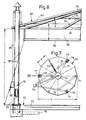
- FIG. 7 has an approximately circular polygonal base plate 72 - a diameter d of eleven meters and a polygon edge length e of slightly more than 280 cm - with a subequoral channel system; an underground air duct is shown in FIG. 7 at 73, other ducts are only indicated. They start radially from a center 74 of the building and are provided with upward-pointing slots or holes for the air supply or removal, which cannot be seen in the drawing.
- the roof 80 has a tubular ring 81 and spoke tubes 82 extending therefrom at an angle q made of sideregle 82.5 / 3.2, which form a pointed roof frame for a roof membrane 83, preferably for a tent skin.
- a vertical feed shaft 85 to the air conveyor 69 or the like.
- the roof 80 is vertically guided on its support columns 78 up to a height h of about five meters (upper position according to 80 'in Fig. 6) and additionally secured by adjustable side sails 87. In the selected exemplary embodiment, the roof 80 is adjusted by means of the crank 88 of a cable 89.
- the lower roof edge 90 is placed on the floor 72, then fine waste is fed centrally via the conduit 69 through the shaft 85 and centrifugally centrifuged off by means of a centrifugal element 84.
- the ring apron 86 forms a baffle as a boundary. If a lower rotting layer M 1 of an example height z of 200 to 400 mm is produced, the roof 80 is raised by this dimension z and another rotting layer is placed.
- layer-by-layer rotting and fungal growth can be controlled, fresh water or pumped-up broods trickling down from spray pipes 91 in the roof area and moistening the rent M.
- the ventilation of the rent M1,. M takes place through the described air channels 73 and their upward slits; the air travels from below through the rent M and is in the headspace, i.e. collected in the roof interior 79 in order to be guided downwards again into the air ducts 73 of the floor. It is also possible to transfer the air there from the roof interior 79 to a neighboring rent.
- the vertical tube 77 in the support column 78 is part of the ventilation system. It can be connected to the roof interior 79 in a manner not shown by means of sliding connections.
Abstract
Description
- Die Erfindung betrifft ein Verfahren und eine Vorrichtung zum Kompostieren von Abfall oder Müll, insbesondere von Grobmüll wie Sträucher od.dgl., wobei der Abfall zerkleinert und einem Lagerplatz zugeführt wird. Darüberhinaus erfaßt die Erfindung ein Fahrzeug, mit den Abfall aufnehmendem Behälter und einem Heckaufbau, welches vor allem zur Durchführung jenes Verfahrens besonders geeignet ist.
- Ein solches Verfahren und eine Vorrichtung mit den Lagerplatz überdeckendem Dach zur Durchführung des Verfahrens sind der AT-PS 375 909 des Erfinders zu entnehmen; hierbei wird in einer großräumigen Anlage der Müll zerkleinert und einer den Rotteplatz überspannenden Halle zugeführt, der unterhalb seiner Sohle mit Luftkanälen versehen ist. Dabei wird die Luft aus dem Kopfraum der entstehenden Miete angesaugt und dann zur Reinigung durch die Miete hindurchgeführt.
- Es ist auch bekannt, Hausmüll mit einem Fahrzeug, welches einen Container mit heckseitiger Einfülleinrichtung aufweist, aufzunehmen sowie zu einer Müllhalde od.dgl. zu transportieren.
- In Kenntnis dieses Standes der Technik hat sich der Erfinder das Ziel gesetzt, ein Verfahren zu schaffen dank dessen eine vereinfachte Behandlung von Müll -- insbesondere Grobmüll wie Gartenabfälle od.dgl. -- , der in verhältnismäßig geringen Mengen an unterschiedlichen Orten entsteht, ermöglicht wird.
- Darüberhinaus soll eine Vorrichtung geschaffen werden, die -- in Unterschied zu einem großen Kompostierwerk -- vereinfacht erstellt werden kann.
- Zur Lösung dieser Aufgabe führt, daß das Zerkleinern des Abfalles während seiner Aufnahme in ein Transportfahrzeug erfolgt und von diesem der zerkleinerte Müll unmittelbar einer Schichtrotte zugeführt wird. Es hat sich als günstig erwiesen, den zerkleinerten Müll einer rundum geschlossenen, nach unten hin offenen und vom Lagerplatz aufragenden Prallkammer od.dgl. zuzufördern und in dieser zu einer Rottenschicht -- bevorzugt durch Zentrifugalkräfte -- zu verteilen, wonach jene Prallkammer um die Höhe der Rottenschicht angehoben und auf deren Oberfläche zur Herstellung einer weiteren Schicht erneut aufgebaut wird.
- Diese Maßgaben erlauben es, verhältnismäßig kleine Schichtrotten auf einfache Weise herzustellen, welche auch nahe des Entstehungsortes des Mülls vorübergehend aufgestellt werden können. In Ergänzung dazu nimmt das nachfolgend beschriebene erfindungsgemäße Fahrzeug den Grobmüll am Ort des Entstehens auf, transportiert ihn in bereits zerkleinerter Form zur Rottevorrichtung, in die er unmittelbar vom Fahrzeug aus gelangt.
- Im Rahmen der Erfindung liegt eine Ausbildung des Transportfahrzeuges dergestalt, daß einem Einlauftrichter eine langsamlaufende Schnecken- oder Schneidmühle nachgeschaltet und über einem Förderelement sowie unterhalb eines Prallraumes angeordnet ist, wobei das Förderelement an einem Durchbruch der Containerrückwand od.dgl. endet, um den zerkleinerten Müll in den Container zu transportieren.
- Bei einer besonders bevorzugten Ausführungsform ist dem Einlauftrichter ein schnellaufender Prallrotor mit an dessen Schlagkreis angrenzendem, entsprechend gekrümmtem Rost nachgeschaltet, der oberhalb des Förderelementes zwischen dem Einlauftrichter und einer Wandung eines Prallraumes verläuft, wobei auch dieses Förderelement am Durchbruch der Heckwand des Fahrzeuges endet. Insbesondere diese Ausführung erlaubt eine sehr effektive Zerkleinerung von Gestrüpp, Geäst und entsprechenden Grobmüllteilen zwischen Prallrotor und Rost - die sehr fein zerkleinerten Partikel fallen durch das Rost auf das Förderelement, während Hartstoffe im Prallraum nach oben geschleudert und über dem Prallraum aufgefangen werden. Dadurch ist es möglich, den zerkleinerten Müll sofort zu deponieren.
- Als günstig hat es sich aus Gründen besserer Handhabung erwiesen, den Einfülltrichter oberhalb der Fahrzeugpritsche anzuordnen, was nun problemlos möglich ist, da der Prallrotor den Grob- und Gartenmüll ohne weiteres "frißt", d.h. die Gefahr eines Zurückschleuderns von Geäst od.dgl. gegen die Förderrichtung ausgeschlossen wird.
- Ein erfindungsgemäß über dem Prallraum angeordneter Sammelkasten zum Auffangen der emporgeschleuderten Hartstoffe ist mit dem Prallraum durch eine mittels einer Klappe verschlossene Oeffnung verbunden; die Hartstoffe schlagen die Klappe auf und gelangen in den Sammelkasten, die Klappe fällt daraufhin selbsttätig auf die Oeffnung zurück.
- Als Förderelement ist einerseits dem Prallrotor und andererseits dem Durchbruch in der Containerrückwand ein Schubboden zugeordnet, dessen Aufgabe es ist, aus dem Rost rieselndes Kleingut mit einer Schubkante aufwärts zum Container zu bringen. Statt des Schubbodens können auch mehrere Förderschnecken vorgesehen werden.
- Der Heckanbau ist um eine etwa im Containerdach vorgesehene Achse vom Fahrzeugheck abschwenkbar und gibt dann eine -- unterhalb des Heckanbaus vorgesehene -- Austragsfördereinrichtung für den auszutragenden Müll frei. Dieses Abschwenken erfolgt vor dem Entladevorgang des Containers - in diesem schiebt eine Schubwand den Müll der Austrags - Fördereinrichtung zu, die bevorzugt als Sammelschnecke ausgebildet und mit einer Förderleitung verbunden ist. Diese wird vor dem Austragen des zerkleinerten Mülls an eine Fremdleitung angeschlossen, in der -- durch eine Schnecke oder durch Druckluft -- die sehr kleinen Müllpartikel einer noch zu schildernden Verteileinrichtung zugeleitet werden.
- Nach einem weiteren Merkmal der Erfindung trägt das Fahrzeug dachwärts einen Drehkranz oder ein entsprechendes Element mit einem Greifarm, dessen Greifeinrichtung um das Fahrzeug schwenkbar ist. Damit wird erreicht, daß der Grobmüll rund um das Fahrzeug aufgenommen und dem Einlauftrichter zugetragen zu werden vermag. Derartige Greifeinrichtungen sind beispielsweise aus DE-GM 84 33 929 an sich bekannt, jedoch bei dem erfindungsgemäßen Fahrzeug in ihrer besonderen Ausgestaltung von großem Nutzen, insbesondere dann, wenn der Greifarm mit einem Gelenk versehen und beide Armteile mittels eines Hydraulikzylinders verbunden sind.
- Von selbständiger erfinderischer Bedeutung ist eine Vorrichtung zum Herstellen einer Schichtrotte oder Miete auf einem Lagerplatz; erfindungsgemäß ist das Dach deckelartig mit daran hängender schürzenartig umlaufender Wandung -- zur Bildung einer Verteiler- oder Prallkammer für zugeführten Müll -- ausgebildet und in unterschiedlichen vertikalen Abständen zum Lagerplatz führbar angebracht. Dieses Dach hat bevorzugt die Form eines Kesselbodens, die schürzenartige Wandung hängt davon beispielsweise in einer Höhe von 800 mm abwärts. Man stellt das Dach mit der Unterkante der Wandung oder Schürze auf den Boden auf und erhält so eine Verteilerkammer für den im Zenit des Daches zugeführten zerkleinerten Müll. Dieser kann von dort aus mittels eines Zellenrades oder eines entsprechenden Schleudergerätes gegen die Innenseite der -- formstabilen, eine Prallwand für die geschleuderten Partikel bildende -- Wandung getrieben werden, so daß sich in einfacher Weise eine Rottenschicht einer Dicke aufbaut, die etwa der Höhe der Wandung entspricht.
- Es hat sich als günstig erwiesen, die Höhe der Wandung veränderlich auszubilden, beispielsweise durch konzentrische Ringe, so daß auch geringere Rottenhöhen ausgelegt zu werden vermögen. Bekanntlich haben sich Schichtdicken von etwa 20 mm als besonders günstig für den Verrottungs- bzw. Kompostierungsvorgang gezeigt.
- Die Schichtrotte wird bevorzugt auf einer mit Luftkanälen versehenen Bodenplatte aufgebaut, welche Tragsäulen für das Dach enthält; letzteres lagert an den Tragsäulen und ist mittels eines Seilzuges od.dgl. höhenverstellbar. Diese Höhenverstellung erlaubt das beschriebene Setzen mehrerer aufeinander liegender Schichten, darüber hinaus bestimmt sie die endgültige Höhe der Schichtrotte, welche bevorzugt fünf bis sechs Meter beträgt.
- Die Tragsäulen sind erfindungsgemäß luftführend ausgebildet und jeweils an einen Luftkanal und ein Luftrohr der Bodenplatte angeschlossen. Es ergibt sich dadurch ein Luftsystem, mit dem die Be- und Entlüftung der entstehenden Schichtrotte ohne weiteres möglich ist. Bevorzugt soll die sich im Kopfraum sammelnde Luft -- wie in AT-PS 375 909 beschrieben -- von unten her der Schichtrotte zugeführt und durch diese reinigend hindurchgeleitet werden. Jedoch ist selbstverständlich auch ein Durchsaugen der Schichtrotte nach unten hin möglich. Je nach Schaltung der Luftführung sind die Tragsäulen in diese als Luftzu- oder als Abförderorgan integriert.
- Das Dach selbst ist verhältnismäßig einfach aufgebaut, besteht es doch aus einem aussteifenden Rohrgestell etwa kesselbodenartiger Kontur, das eine darauf aufgespannte Dachhaut, bevorzugt aus Zeltstoff, sowie jene Schürze oder Wandung trägt.
- Insgesamt ergibt sich eine sehr große Vereinfachung des Zerkleinerungs- und Kompostiervorganges für Grobmüll, insbesondere für an Schwerpunkten gesammelten Garten- oder Feldmüll.
- Weitere Vorteile, Merkmale und Einzelheiten der Erfindung ergeben sich aus der nachfolgenden Beschreibung bevorzugter Ausführungsbeispiele sowie anhand der Zeichnung; diese zeigt in
- Fig. 1 die Seitenansicht eines teilweise geschnittenen Fahrzeuges;
- Fig. 2 ein vergrößertes Detail aus Fig. 1, gesehen in deren Pfeilrichtung II;
- Fig. 3 ein vergrößertes Detail aus Fig. 1 zu einer anderen Ausführug;
- Fig. 4 ein Teil der Fig. 3 in Draufsicht;
- Fig. 5 das Teil der Fig. 4 in Schrägsicht;
- Fig. 6 einen schematisierten Längsschnitt durch eine Kompostierungsvorrichtung;
- Fig. 7 die Draufsicht auf einen Teil der Fig. 6:
- Fig. 8 einen vergrößerten Vertikalschnitt durch einen Teil der Fig. 6.
- Ein Sammelfahrzeug 10 weist auf einer -- Luftreifen 11 überspannenden -- Pritsche 12 einen quaderartigen Containeraufbau 14 auf, dessen Dach 15 nahe der an ein Fahrerhaus 13 grenzenden Frontwand 16 einen Drehkranz 19 für einen Greiferarm 20 trägt. An letzterem ist ein Unterarm 21 angelenkt und mittels eines dem Gelenk 22 zugeordneten Hydraulikzylinders 23 steuerbar. Am freien Ende des Unterarms 21 hängt eine Greifeinrichtung 24. Dieser Greifer 20 bis 24 ist um das gesamte Fahrzeug 10 schwenkbar.
- Im Containerinnenraum 26 ist in Pfeilrichtung x eine Schubwand 28 mittels eines Hydraulikzylinders 23 zwischen Frontwand 16 und einer geneigten Stau- oder Heckwand 17 bewegbar angebracht.
- Ein Heckanbau 30 des Fahrzeuges 10 ist mit einem abkragenden Einfülltrichter 32 für Grobmüll, wie Sträucher od.dgl. versehen. Dessen in einem Winkel w von beispielsweise 40° gegen die Horizontale H geneigtem Boden 33 steht in einem Abstand a eine -- von einem Hydraulikzylinder 23p schwenkbare Preßplatte 35 gegenüber, die oberhalb einer Schneid- oder Schneckenmühle 36 mit langsamlaufenden Walzen angelenkt ist. Diese ist einer Rückhalteeinrichtung 38 -- einer Klappe, einem Kamm oder Pendelzähnen -- vorgeschaltet, die einen Fußschlitz 39 der Stauwand 17 abdeckt.
- Unterhalb der Schnecken- oder Schneidmühle 36 verläuft parallel zu ihr und in einem Winkel t von etwa 45° zur Horizontalen H ein Schubboden 40 mit Hydraulikzylinder 41 - weiter oben angeordnete Hydraulikeinrichtungen 42 erlauben im übrigen ein Abklappen des Heckanbaus um eine Achse 29 im Dachbereich.
- Unterhalb jenes -- mit einer Schubkante 43 ausgerüsteten -- Schubbodens 40 und oberhalb eines Trichters 44 verläuft eine Förderschnecke 45. In den Trichter 44 mündet die Luftleitung 46 eines Gebläses 47 - andernends ist ein Schnellverschluß 48 für eine bei 49 angedeutete Fremdleitung zu erkennen.
- Bei dem bevorzugten Ausführungsbeispiel des Heckanbaus 30n in Figur 3 hängen von der Decke 34 des Einfülltrichters 32 aus Sicherheitsgründen Gummischürzen 51 in den Trichterraum 32a. In Einführrichtung y hinter den Gummischürzen 51 ist eine achsparallel schwenkbare Einzug-Stachelwalze 52 vorgesehen und unterhalb dieser -- über einem gekrümmten Rost 54 -- ein Prallrotor 56, wie er beispielhaft in der Schrift zum DE-GM 87 04 007 beschrieben ist. Jener gekrümmte Rost 54 sitzt zwischen dem Boden 33 des Einfülltrichters 32 und einer geneigten Zwischenwand 58, die mit einer Anbauaußenwand 59 des Heckanbaus 30 einen Prallraum 60 begrenzt. Die Anbauaußenwand 59 endet am Prallrotor 56 mit einem Prallkamm 61.
- An den Prallraum 60 schließt nach oben hin ein Sammelkasten 62 für Steine 63 od.dgl. Hartteile an, welche durch eine mittels einer Klappe 64 verschließbare Oeffnung 65 einer Querplatte 66 aufwärts gelangen und beliebig entfernt werden können. Beim Aufwärtsschleudern der Steine 63 od.dgl. wird die Klappe 64 nach oben hin geöffnet und fällt anschließend selbsttätig auf die Oeffnung 65 zurück.
- In Fig. 3 sind die zu Fig. 1 beschriebenen Teile 44 bis 49 ebenfalls vorhanden, aus Gründen besserer Uebersichtlichkeit jedoch in der Darstellung vernachlässigt.
- Statt des in Fig. 5 vergrößerten Schubbodens 40 sind als Zuführorgane für das durch das Rost 54 fallende Partikel zum Containerinnenraum 26 auch mehrere Förderschnecken denkbar; der Grobmüll wie Sträucher od.dgl. wird von der achsparallel bewegbaren Einzugswalze 52 dem Prallrotor 56 zugeführt, dank diesem über dem gekrümmten Rost 54 zerkleinert und fällt durch letzteres auf den Schubboden 40. Von diesem -- oder, wie gesagt, einem entsprechenden Förderer -- gelangen die zerkleinerten Teile in den Containerraum 26; Hartstoffe werden nach oben durch den Prallraum 58 in den Sammelkasten 62 gefördert.
- Ist das Fahrzeug 10 gemäß Fig. 6 am Entladeort angekommen, wird der Heckanbau 30, 30n um seine Achse 29 hochgeklappt und die Abfördereinrichtungen 44 bis 48 in Betrieb genommen; die Fremdleitung 49 wird angeschlossen und die Schubwand 28 beginnt, den Containerinhalt dem Fußschlitz 39 in der Heckwand 17 zuzuschieben.
- Der zerkleinerte und hartstoffreie Müll gelangt durch eine trogartige Zwischenstation 68 mit integrierter Förderschnecke oder über eine Luftförderanlage 69 zu einer Kleinrotteanlage 70.
- Die Rotte-Anlage 70 besitzt gemäß Fig. 7 eine annähernd kreisförmige polygone Bodenplatte 72 -- eines Durchmessers d von elf Metern und einer Polygonkantenlänge e von etwas mehr als 280 cm -- mit subaequoralem Kanalsystem; ein unterirdischer Luftkanal ist in Fig. 7 bei 73 dargestellt, andere Kanäle sind nur angedeutet. Sie gehen radial von einem Zentrum 74 des Bauwerkes aus und sind mit nach oben hin weisenden -- in der Zeichnung nicht erkennbaren -- Schlitzen oder Löchern für die Luftzu- oder Abfuhr versehen.
- Außerdem sind in Fig. 7, 8 Luftrohre 76 zu erkennen, die zum einen vom Zentrum 74 zu einem Knotenpunkt 75 -- mit Saug- oder Druckvorrichtung -- laufen sowie von diesem zu vertikalen Rohren 77, von denen drei in Tragsäulen 78 eines Daches 80 enthalten sind.
- Das Dach 80 weist einen Rohrring 81 und davon in einem Winkel q ausgehende Speichenrohre 82 aus Siderohr 82,5/3,2 auf, die ein Spitzdachgestell für eine Dachmembrane 83 bilden, bevorzugt für eine Zelthaut. Im Dachzenit 74z ist ein vertikaler Zuführschacht 85 an die Luftförderanlage 69 od.dgl. angeschlossen, unterhalb der Dachmembrane 83 am Dachgestell 81/82 eine formstabile Ringschürze 86 einer Höhe n von etwa 800 mm festgelegt. Letztere kann verstellt werden.
- Das Dach 80 ist an seinen Tragsäulen 78 vertikal bis zu einer Höhe h von etwa fünf Metern verfahrbar geführt (obere Lage gemäß 80′ in Fig. 6) und durch verstellbare seitliche Absegelungen 87 zusätzlich gesichert. Ein Verstellen des Daches 80 geschieht im gewählten Ausführungsbeispiel mittels der Kurbel 88 eines Seilzuges 89.
- Um eine Miete M zu errichten, wird der untere Dachrand 90 auf den Boden 72 aufgesetzt, dann wird über die Leitung 69 Feinmüll zentrisch durch den Schacht 85 zugeführt und mittels eines Schleuderorganes 84 radial abgeschleudert. Dabei bildet die Ringschürze 86 eine Prallwand als Begrenzung. Ist eine untere Rottenschicht M₁ einer beispielsweisen Höhe z von 200 bis 400 mm hergestellt, wird das Dach 80 etwa um dieses Maß z angehoben und eine weitere Rottenschicht gesetzt.
- So kann ein schichtenweises Verrotten und Verpilzen gesteuert werden, wobei aus Sprührohren 91 des Dachbereiches Frischwasser oder hinaufgepumpte Brüten herabrieseln und die Miete M befeuchten.
- Die Belüftung der Miete M₁bzw. M erfolgt durch die beschriebenen Luftkanäle 73 und deren aufwärts gerichtete Schlitze; die Luft wandert von unten her durch die Miete M und wird im Kopfraum, d.h. im Dachinnenraum 79 gesammelt, um wieder abwärts in die Luftkanäle 73 des Bodens geführt zu werden. Auch ist es möglich, aus dem Dachinnenraum 79 dort vorhandene Luft in eine Nachbarmiete zu überführen.
- Selbstverständlich liegt es im Rahmen der Erfindung, die Luftführung anders zu gestalten, d.h. die Luft aus dem Dachinnenraum 79 durch die Miete bodenwärts zu saugen und durch die Luftkanäle 73 abzuführen.
- In beiden Fällen ist das Vertikalrohr 77 in der Tragsäule 78 Teil des Be- bzw. Entlüftungssystems. Es kann in nicht dargestellter Weise mittels Gleitstutzen an den Dachinnenraum 79 angeschlossen sein.
Claims (15)
dadurch gekennzeichnet,
daß das Zerkleinern des Abfalles während seiner Aufnahme in ein Transportfahrzeug erfolgt und von diesem der zerkleinerte Müll unmittelbar einer Schüttrotte zugeführt wird.
Applications Claiming Priority (2)
| Application Number | Priority Date | Filing Date | Title |
|---|---|---|---|
| DE3735362A DE3735362C2 (de) | 1987-10-19 | 1987-10-19 | Verfahren zum Kompostieren von Abfall und Vorrichtung zum Herstellen einer Schichtrotte |
| DE3735362 | 1987-10-19 |
Publications (3)
| Publication Number | Publication Date |
|---|---|
| EP0313034A2 true EP0313034A2 (de) | 1989-04-26 |
| EP0313034A3 EP0313034A3 (en) | 1989-07-26 |
| EP0313034B1 EP0313034B1 (de) | 1994-06-29 |
Family
ID=6338649
Family Applications (1)
| Application Number | Title | Priority Date | Filing Date |
|---|---|---|---|
| EP19880117428 Expired - Lifetime EP0313034B1 (de) | 1987-10-19 | 1988-10-19 | Fahrzeug zum Kompostieren von Abfall oder Müll |
Country Status (4)
| Country | Link |
|---|---|
| US (2) | US5104805A (de) |
| EP (1) | EP0313034B1 (de) |
| AT (1) | ATE107918T1 (de) |
| DE (2) | DE3735362C2 (de) |
Cited By (1)
| Publication number | Priority date | Publication date | Assignee | Title |
|---|---|---|---|---|
| CN104370124A (zh) * | 2014-10-22 | 2015-02-25 | 鞍钢集团矿业公司 | 固定破碎站伸缩臂式抑尘装置 |
Families Citing this family (3)
| Publication number | Priority date | Publication date | Assignee | Title |
|---|---|---|---|---|
| US20040171136A1 (en) * | 2002-11-01 | 2004-09-02 | Holtzapple Mark T. | Methods and systems for pretreatment and processing of biomass |
| GB2415666B (en) * | 2004-06-29 | 2006-05-31 | Coolderry Plant Ltd | Truck |
| WO2006063289A2 (en) * | 2004-12-10 | 2006-06-15 | The Texas A & M University System | System and method for processing biomass |
Citations (6)
| Publication number | Priority date | Publication date | Assignee | Title |
|---|---|---|---|---|
| DE1083186B (de) * | 1955-03-03 | 1960-06-09 | Passavant Werke | Gaersilo fuer Kompostbereitung |
| US3356116A (en) * | 1964-03-06 | 1967-12-05 | Brundell & Jonsson Aktiebolag | Method and means for forest harvesting |
| FR2003153A1 (de) * | 1968-03-04 | 1969-11-07 | Schwarting Bernhard | |
| FR2263992A1 (en) * | 1974-03-11 | 1975-10-10 | Prat Felix | Refuse disposal for rural settlements by composting - with mobile sorting and gridning plant to serve several settlements |
| DE3104769A1 (de) * | 1981-02-11 | 1982-09-16 | Ernst 7326 Heiningen Weichel | Verfahren und vorrichtung zur gewinnung nutzbarer waerme durch schnellverrottung bzw. kompostierung, insbesondere pflanzlicher abfallstoffe sowie stallmist |
| US4397674A (en) * | 1981-11-20 | 1983-08-09 | Bancohio National Bank | Material treatment and windrowing apparatus |
Family Cites Families (11)
| Publication number | Priority date | Publication date | Assignee | Title |
|---|---|---|---|---|
| US1832179A (en) * | 1927-11-16 | 1931-11-17 | Boggiano-Pico Luigi | Plant for treating organic refuse |
| US2222651A (en) * | 1936-12-17 | 1940-11-26 | Underpinning & Foundation Comp | Fermentation cell for converting organic matter to humus |
| US3355116A (en) * | 1964-10-01 | 1967-11-28 | Celanese Corp | Yarn takeup |
| AT276274B (de) * | 1968-04-16 | 1969-11-25 | Rheinstahl Wanheim Ges Mit Bes | Anlage zur Herstellung von Grünmalz bzw. Darrmalz |
| US3954194A (en) * | 1974-10-15 | 1976-05-04 | Caterpillar Tractor Co. | Material grasping apparatus |
| DE2523709C3 (de) * | 1975-05-28 | 1978-09-21 | Christian Konrad 8251 St Wolfgang Numberger | Anlage zur Erzeugung von Grünmalz aus geweichter Gerste und/oder zur Bevorratung und kontinuierlichen Abgabe von Grunmalz |
| EP0004094B2 (de) * | 1978-03-13 | 1988-03-23 | Werner Bürklin | Vorrichtung zum Aufbereiten von kompostierfähigem Material |
| DE3117451A1 (de) * | 1981-05-02 | 1982-11-18 | Manfred 6601 Kleinblittersdorf Kany | "verrottungsanlage" |
| DE3262997D1 (en) * | 1981-09-10 | 1985-05-15 | Kloeckner Humboldt Deutz Ag | Loading vehicle for plant stalks |
| DE3444609A1 (de) * | 1984-12-07 | 1986-06-19 | Alfred Dr.-Ing. 7900 Ulm Eggenmüller | Verfahren und einrichtung zum saeubern von anlagen |
| SU1470213A1 (ru) * | 1987-08-03 | 1989-04-07 | Сибирский научно-исследовательский институт механизации и электрификации сельского хозяйства | Погрузчик навоза |
-
1987
- 1987-10-19 DE DE3735362A patent/DE3735362C2/de not_active Expired - Fee Related
-
1988
- 1988-10-18 US US07/259,175 patent/US5104805A/en not_active Expired - Fee Related
- 1988-10-19 EP EP19880117428 patent/EP0313034B1/de not_active Expired - Lifetime
- 1988-10-19 DE DE3850470T patent/DE3850470D1/de not_active Expired - Fee Related
- 1988-10-19 AT AT88117428T patent/ATE107918T1/de not_active IP Right Cessation
-
1992
- 1992-01-27 US US07/826,021 patent/US5356258A/en not_active Expired - Fee Related
Patent Citations (6)
| Publication number | Priority date | Publication date | Assignee | Title |
|---|---|---|---|---|
| DE1083186B (de) * | 1955-03-03 | 1960-06-09 | Passavant Werke | Gaersilo fuer Kompostbereitung |
| US3356116A (en) * | 1964-03-06 | 1967-12-05 | Brundell & Jonsson Aktiebolag | Method and means for forest harvesting |
| FR2003153A1 (de) * | 1968-03-04 | 1969-11-07 | Schwarting Bernhard | |
| FR2263992A1 (en) * | 1974-03-11 | 1975-10-10 | Prat Felix | Refuse disposal for rural settlements by composting - with mobile sorting and gridning plant to serve several settlements |
| DE3104769A1 (de) * | 1981-02-11 | 1982-09-16 | Ernst 7326 Heiningen Weichel | Verfahren und vorrichtung zur gewinnung nutzbarer waerme durch schnellverrottung bzw. kompostierung, insbesondere pflanzlicher abfallstoffe sowie stallmist |
| US4397674A (en) * | 1981-11-20 | 1983-08-09 | Bancohio National Bank | Material treatment and windrowing apparatus |
Cited By (2)
| Publication number | Priority date | Publication date | Assignee | Title |
|---|---|---|---|---|
| CN104370124A (zh) * | 2014-10-22 | 2015-02-25 | 鞍钢集团矿业公司 | 固定破碎站伸缩臂式抑尘装置 |
| CN104370124B (zh) * | 2014-10-22 | 2016-05-04 | 鞍钢集团矿业公司 | 固定破碎站伸缩臂式抑尘装置 |
Also Published As
| Publication number | Publication date |
|---|---|
| EP0313034A3 (en) | 1989-07-26 |
| US5104805A (en) | 1992-04-14 |
| US5356258A (en) | 1994-10-18 |
| EP0313034B1 (de) | 1994-06-29 |
| DE3735362A1 (de) | 1989-05-03 |
| ATE107918T1 (de) | 1994-07-15 |
| DE3735362C2 (de) | 1997-06-19 |
| DE3850470D1 (de) | 1994-08-04 |
Similar Documents
| Publication | Publication Date | Title |
|---|---|---|
| EP0004094B1 (de) | Vorrichtung zum Aufbereiten von kompostierfähigem Material | |
| DE202005021545U1 (de) | Vorrichtung zum Zerkleinern von Haufwerk | |
| DE2351548A1 (de) | Lufttrommel-sortierer fuer festen abfall | |
| EP0443315A1 (de) | Abfallaufbereitungsanlage | |
| DE3827282C2 (de) | ||
| EP0313034A2 (de) | Fahrzeug zum Kompostieren von Abfall oder Müll | |
| EP0339490B1 (de) | Vorrichtung zum Sortieren von Bauschutt | |
| EP0523009B1 (de) | Kompostieranlage | |
| DE4239305C2 (de) | Verfahren und Vorrichtung zum Befüllen und Entleeren eines Rottebehälters | |
| DE3606273C2 (de) | ||
| CH632227A5 (en) | Plant for composting a mixture of sewage sludge and waste material containing household rubbish | |
| DE4203720C2 (de) | Verfahren und Vorrichtung zum Herstellen eines Düngemittels aus Traubentrester | |
| EP0569919B1 (de) | Umsetzmaschine zur Aufbereitung von in offenen oder geschlossenen Mietenbehältern lagernden Stoffmengen | |
| DE3924844A1 (de) | Verfahren und zugehoerige einrichtungen zur schnellen heissverrottung organischer abfaelle | |
| DE4000510C2 (de) | Verfahren und Anlage zum Kompostieren von Müll | |
| DE3829658C1 (de) | ||
| DE19628438C2 (de) | Mobile Anlage zur Aufnahme und Vorverarbeitung von Hartschaum-Körpern | |
| DE2547134A1 (de) | Verfahren und vorrichtung zur aufbereitung und hygienisierung von muell bzw. muell-klaerschlammgemischen mittels kompostierung | |
| DE3708558C2 (de) | ||
| DE4025681A1 (de) | Rottebett-anlage | |
| AT398072B (de) | Vorrichtung zum kompostieren organischer abfälle | |
| DE2302805A1 (de) | Karussellanlage fuer die kompostierung von muell | |
| DE4201399A1 (de) | Verfahren zur kompostierung von organischen abfaellen | |
| AT519811B1 (de) | Vorrichtung und Verfahren zum Verteilen von Schüttgut | |
| DE1094275B (de) | Anlage zur kontinuierlichen Kompostierung von Stadtmuell |
Legal Events
| Date | Code | Title | Description |
|---|---|---|---|
| PUAI | Public reference made under article 153(3) epc to a published international application that has entered the european phase |
Free format text: ORIGINAL CODE: 0009012 |
|
| AK | Designated contracting states |
Kind code of ref document: A2 Designated state(s): AT BE CH DE ES FR GB GR IT LI LU NL SE |
|
| PUAL | Search report despatched |
Free format text: ORIGINAL CODE: 0009013 |
|
| AK | Designated contracting states |
Kind code of ref document: A3 Designated state(s): AT BE CH DE ES FR GB GR IT LI LU NL SE |
|
| RBV | Designated contracting states (corrected) |
Designated state(s): AT BE CH DE ES FR GB IT LI NL SE |
|
| 17P | Request for examination filed |
Effective date: 19900109 |
|
| 17Q | First examination report despatched |
Effective date: 19910701 |
|
| GRAA | (expected) grant |
Free format text: ORIGINAL CODE: 0009210 |
|
| AK | Designated contracting states |
Kind code of ref document: B1 Designated state(s): AT BE CH DE ES FR GB IT LI NL SE |
|
| PG25 | Lapsed in a contracting state [announced via postgrant information from national office to epo] |
Ref country code: NL Effective date: 19940629 Ref country code: GB Effective date: 19940629 Ref country code: ES Free format text: THE PATENT HAS BEEN ANNULLED BY A DECISION OF A NATIONAL AUTHORITY Effective date: 19940629 Ref country code: BE Effective date: 19940629 |
|
| REF | Corresponds to: |
Ref document number: 107918 Country of ref document: AT Date of ref document: 19940715 Kind code of ref document: T |
|
| REF | Corresponds to: |
Ref document number: 3850470 Country of ref document: DE Date of ref document: 19940804 |
|
| ITF | It: translation for a ep patent filed |
Owner name: DE DOMINICIS & MAYER S.R.L. |
|
| PG25 | Lapsed in a contracting state [announced via postgrant information from national office to epo] |
Ref country code: SE Effective date: 19940929 |
|
| ET | Fr: translation filed | ||
| NLV1 | Nl: lapsed or annulled due to failure to fulfill the requirements of art. 29p and 29m of the patents act | ||
| GBV | Gb: ep patent (uk) treated as always having been void in accordance with gb section 77(7)/1977 [no translation filed] |
Effective date: 19940629 |
|
| PLBE | No opposition filed within time limit |
Free format text: ORIGINAL CODE: 0009261 |
|
| STAA | Information on the status of an ep patent application or granted ep patent |
Free format text: STATUS: NO OPPOSITION FILED WITHIN TIME LIMIT |
|
| 26N | No opposition filed | ||
| PGFP | Annual fee paid to national office [announced via postgrant information from national office to epo] |
Ref country code: CH Payment date: 19960112 Year of fee payment: 8 |
|
| PGFP | Annual fee paid to national office [announced via postgrant information from national office to epo] |
Ref country code: AT Payment date: 19961009 Year of fee payment: 9 |
|
| PG25 | Lapsed in a contracting state [announced via postgrant information from national office to epo] |
Ref country code: LI Effective date: 19961031 Ref country code: CH Effective date: 19961031 |
|
| PGFP | Annual fee paid to national office [announced via postgrant information from national office to epo] |
Ref country code: DE Payment date: 19961205 Year of fee payment: 9 |
|
| REG | Reference to a national code |
Ref country code: CH Ref legal event code: PL |
|
| PG25 | Lapsed in a contracting state [announced via postgrant information from national office to epo] |
Ref country code: AT Free format text: LAPSE BECAUSE OF NON-PAYMENT OF DUE FEES Effective date: 19971019 |
|
| PGFP | Annual fee paid to national office [announced via postgrant information from national office to epo] |
Ref country code: FR Payment date: 19980420 Year of fee payment: 10 |
|
| PG25 | Lapsed in a contracting state [announced via postgrant information from national office to epo] |
Ref country code: DE Free format text: LAPSE BECAUSE OF NON-PAYMENT OF DUE FEES Effective date: 19980701 |
|
| PG25 | Lapsed in a contracting state [announced via postgrant information from national office to epo] |
Ref country code: FR Free format text: LAPSE BECAUSE OF NON-PAYMENT OF DUE FEES Effective date: 19990630 |
|
| REG | Reference to a national code |
Ref country code: FR Ref legal event code: ST |
|
| PG25 | Lapsed in a contracting state [announced via postgrant information from national office to epo] |
Ref country code: IT Free format text: LAPSE BECAUSE OF NON-PAYMENT OF DUE FEES;WARNING: LAPSES OF ITALIAN PATENTS WITH EFFECTIVE DATE BEFORE 2007 MAY HAVE OCCURRED AT ANY TIME BEFORE 2007. THE CORRECT EFFECTIVE DATE MAY BE DIFFERENT FROM THE ONE RECORDED. Effective date: 20051019 |