EP0312862A2 - Hochdruckreinigungsgerät - Google Patents
Hochdruckreinigungsgerät Download PDFInfo
- Publication number
- EP0312862A2 EP0312862A2 EP88116715A EP88116715A EP0312862A2 EP 0312862 A2 EP0312862 A2 EP 0312862A2 EP 88116715 A EP88116715 A EP 88116715A EP 88116715 A EP88116715 A EP 88116715A EP 0312862 A2 EP0312862 A2 EP 0312862A2
- Authority
- EP
- European Patent Office
- Prior art keywords
- pressure
- cleaning device
- sealing
- pressure cleaning
- housing
- Prior art date
- Legal status (The legal status is an assumption and is not a legal conclusion. Google has not performed a legal analysis and makes no representation as to the accuracy of the status listed.)
- Withdrawn
Links
Images


Classifications
-
- B—PERFORMING OPERATIONS; TRANSPORTING
- B08—CLEANING
- B08B—CLEANING IN GENERAL; PREVENTION OF FOULING IN GENERAL
- B08B3/00—Cleaning by methods involving the use or presence of liquid or steam
- B08B3/02—Cleaning by the force of jets or sprays
- B08B3/026—Cleaning by making use of hand-held spray guns; Fluid preparations therefor
-
- B—PERFORMING OPERATIONS; TRANSPORTING
- B05—SPRAYING OR ATOMISING IN GENERAL; APPLYING FLUENT MATERIALS TO SURFACES, IN GENERAL
- B05B—SPRAYING APPARATUS; ATOMISING APPARATUS; NOZZLES
- B05B9/00—Spraying apparatus for discharge of liquids or other fluent material, without essentially mixing with gas or vapour
- B05B9/03—Spraying apparatus for discharge of liquids or other fluent material, without essentially mixing with gas or vapour characterised by means for supplying liquid or other fluent material
- B05B9/04—Spraying apparatus for discharge of liquids or other fluent material, without essentially mixing with gas or vapour characterised by means for supplying liquid or other fluent material with pressurised or compressible container; with pump
- B05B9/0403—Spraying apparatus for discharge of liquids or other fluent material, without essentially mixing with gas or vapour characterised by means for supplying liquid or other fluent material with pressurised or compressible container; with pump with pumps for liquids or other fluent material
- B05B9/0413—Spraying apparatus for discharge of liquids or other fluent material, without essentially mixing with gas or vapour characterised by means for supplying liquid or other fluent material with pressurised or compressible container; with pump with pumps for liquids or other fluent material with reciprocating pumps, e.g. membrane pump, piston pump, bellow pump
-
- B—PERFORMING OPERATIONS; TRANSPORTING
- B05—SPRAYING OR ATOMISING IN GENERAL; APPLYING FLUENT MATERIALS TO SURFACES, IN GENERAL
- B05B—SPRAYING APPARATUS; ATOMISING APPARATUS; NOZZLES
- B05B9/00—Spraying apparatus for discharge of liquids or other fluent material, without essentially mixing with gas or vapour
- B05B9/03—Spraying apparatus for discharge of liquids or other fluent material, without essentially mixing with gas or vapour characterised by means for supplying liquid or other fluent material
- B05B9/04—Spraying apparatus for discharge of liquids or other fluent material, without essentially mixing with gas or vapour characterised by means for supplying liquid or other fluent material with pressurised or compressible container; with pump
- B05B9/0403—Spraying apparatus for discharge of liquids or other fluent material, without essentially mixing with gas or vapour characterised by means for supplying liquid or other fluent material with pressurised or compressible container; with pump with pumps for liquids or other fluent material
- B05B9/0426—Spraying apparatus for discharge of liquids or other fluent material, without essentially mixing with gas or vapour characterised by means for supplying liquid or other fluent material with pressurised or compressible container; with pump with pumps for liquids or other fluent material with a pump attached to the spray gun or discharge device
-
- B—PERFORMING OPERATIONS; TRANSPORTING
- B08—CLEANING
- B08B—CLEANING IN GENERAL; PREVENTION OF FOULING IN GENERAL
- B08B3/00—Cleaning by methods involving the use or presence of liquid or steam
- B08B3/02—Cleaning by the force of jets or sprays
- B08B3/026—Cleaning by making use of hand-held spray guns; Fluid preparations therefor
- B08B3/028—Spray guns
-
- F—MECHANICAL ENGINEERING; LIGHTING; HEATING; WEAPONS; BLASTING
- F04—POSITIVE - DISPLACEMENT MACHINES FOR LIQUIDS; PUMPS FOR LIQUIDS OR ELASTIC FLUIDS
- F04B—POSITIVE-DISPLACEMENT MACHINES FOR LIQUIDS; PUMPS
- F04B1/00—Multi-cylinder machines or pumps characterised by number or arrangement of cylinders
- F04B1/12—Multi-cylinder machines or pumps characterised by number or arrangement of cylinders having cylinder axes coaxial with, or parallel or inclined to, main shaft axis
- F04B1/20—Multi-cylinder machines or pumps characterised by number or arrangement of cylinders having cylinder axes coaxial with, or parallel or inclined to, main shaft axis having rotary cylinder block
- F04B1/2014—Details or component parts
- F04B1/2064—Housings
-
- F—MECHANICAL ENGINEERING; LIGHTING; HEATING; WEAPONS; BLASTING
- F04—POSITIVE - DISPLACEMENT MACHINES FOR LIQUIDS; PUMPS FOR LIQUIDS OR ELASTIC FLUIDS
- F04B—POSITIVE-DISPLACEMENT MACHINES FOR LIQUIDS; PUMPS
- F04B17/00—Pumps characterised by combination with, or adaptation to, specific driving engines or motors
- F04B17/03—Pumps characterised by combination with, or adaptation to, specific driving engines or motors driven by electric motors
-
- F—MECHANICAL ENGINEERING; LIGHTING; HEATING; WEAPONS; BLASTING
- F04—POSITIVE - DISPLACEMENT MACHINES FOR LIQUIDS; PUMPS FOR LIQUIDS OR ELASTIC FLUIDS
- F04B—POSITIVE-DISPLACEMENT MACHINES FOR LIQUIDS; PUMPS
- F04B17/00—Pumps characterised by combination with, or adaptation to, specific driving engines or motors
- F04B17/06—Mobile combinations
-
- B—PERFORMING OPERATIONS; TRANSPORTING
- B05—SPRAYING OR ATOMISING IN GENERAL; APPLYING FLUENT MATERIALS TO SURFACES, IN GENERAL
- B05B—SPRAYING APPARATUS; ATOMISING APPARATUS; NOZZLES
- B05B9/00—Spraying apparatus for discharge of liquids or other fluent material, without essentially mixing with gas or vapour
- B05B9/01—Spray pistols, discharge devices
-
- B—PERFORMING OPERATIONS; TRANSPORTING
- B08—CLEANING
- B08B—CLEANING IN GENERAL; PREVENTION OF FOULING IN GENERAL
- B08B2203/00—Details of cleaning machines or methods involving the use or presence of liquid or steam
- B08B2203/02—Details of machines or methods for cleaning by the force of jets or sprays
- B08B2203/0223—Electric motor pumps
-
- B—PERFORMING OPERATIONS; TRANSPORTING
- B08—CLEANING
- B08B—CLEANING IN GENERAL; PREVENTION OF FOULING IN GENERAL
- B08B2203/00—Details of cleaning machines or methods involving the use or presence of liquid or steam
- B08B2203/02—Details of machines or methods for cleaning by the force of jets or sprays
- B08B2203/027—Pump details
Definitions
- the invention relates to a high-pressure cleaning device, consisting of a pressure-generating unit with a spray gun.
- Such high-pressure cleaning devices are known, namely in a movable and also in a portable design.
- Piston pumps in particular axial piston pumps or in-line piston pumps, are used to generate the pressure.
- the main disadvantage is that these known devices are cumbersome to handle, in which the actual printing unit is arranged in a chassis or support frame, to which the spray gun is then connected.
- These known devices are particularly difficult to handle even when they are to be operated at different locations. The range of action is restricted due to the necessary connection of the devices to a high pressure hose.
- the known devices are expensive and a number of connections have to be made so that the devices are functional.
- the invention has for its object to design a device of the known type so that it as a simple hand-held device with the water pipe and, if necessary, connected to the power grid, is ready for use.
- the pressure unit consisting of a multi-axial piston pump and an electric motor, is included in the head of the spray gun and the pump housing is connected to the pistol grip.
- the pump has a fixed swash plate which is associated with a driven disc provided with axial pistons, the pistons being guided on the inclined surface of the swash plate and that between the driven disc and the housing with the suction and pressure connection Sealing disc is arranged.
- a further advantageous embodiment provides that the pistons on the sealing disk are connected to their pressure and suction sides with circularly arranged slots.
- the swash plate is rotatably arranged on the housing and connected to the drive shaft by means of a ball joint, and that the piston is arranged on further ball joints on the swash plate.
- a retaining washer rests on the sealing washer, with a plurality of pressure bolts in the area of the annular channel on the pressure side arranged in the sealing washer and dan the retaining washer are supported.
- the self-adjusting sealing washer is spherical on its outer circumference.
- an overpressure valve be arranged between the pressure side and the suction side.
- the invention has the advantage that the device is easy to use, and the radius of action can be extended almost as desired without a substantial reduction in performance.
- the low weight of the device is also favorable for handling.
- the compact design of the device is also favored by the special design of the pump.
- the embodiment of the invention also has the advantage that large amounts of water can be dispensed at high pressure. This design also makes it possible to dispense with suction and pressure valves, which means that the design can be significantly reduced.
- the pump according to the invention can also be used for higher outputs for other purposes, ie as an independent pump that is independent of a hand-held device.
- FIG. 1 shows such a spray gun, the pump housing 2 being arranged on the handle 1, to which a motor 3 is also attached.
- a valve housing 4 with a spray tube 5 and a spray nozzle 6 is also attached to the pump housing 2.
- a water hose 7 is connected to the valve housing 4, the electrical connection 8 for the motor 3 also being provided at a suitable point.
- FIGS. 2 and 3 show the special embodiment of the axial piston pump used, with a fixed swash plate 10 being attached to the motor 3 is flanged.
- the pump shaft 11 is mounted on this disk 10, and the pump housing 2 is also flanged to this disk 10.
- a driven disk 12 is connected to the shaft 11, in which a plurality of pistons 13, in the exemplary embodiment shown there are four pistons 13, are displaceably guided.
- the head 14 of the pistons 13 lies against the inclined surface 15 of the disk 10.
- the pressure is applied with the aid of springs 16.
- a sliding disk 17 is fastened in a sealed manner to the driven disk 12 and bears against a sealing disk 18 attached to the pump housing 2.
- the sealing disk 18 connects the cylinders of the pistons 13 to the suction channel 19 or the pressure channel 20.
- a pressure relief valve 21 is located between the two channels.
- the spray tube 5 is connected to the pressure channel 20 and the water hose 7 to the suction channel 19.
- the shaft 11 for the motor 3 is driven via
- Circular slots 23 and 24 are arranged in the sealing disk 18. These slots ensure that the cylinders of the pistons 13 are connected to the outlet 20 during their pushing movement and to the port 19 during their suction movement.
- the pump shaft 11 is guided through the driven disk 12 and connected at a ball joint 25 to the swash plate 10, which is mounted on the housing 2.
- the ends of the pump pistons 13 are arranged on further ball joints 26 on the circumference of the swash plate 10.
- a holding washer 27 is arranged on the outside of the sealing washer 18, the sealing washer 18 pressing the sealing washer 18 against the sliding washer 17.
- compression springs 28 are provided in the area of the ring channel 23 belonging to the suction channel 19 and are pressed by the housing 2 against the holding disc 27.
- individual pressure pins 29 are arranged so as to be axially displaceable, these pressure pins 29 abutting on the retaining disk 27. Due to the pressure applied to the pressure pin 29, the sealing washer 18 is pressed against the sliding washer 17.
- a tube 30 is arranged in the retaining disk for sealing the pressure channel 20 leading to the outside, which tube is sealed both in the sealing disk 18 and in the housing 2.
- the sealing disk 18 has a spherical surface 31 on its outer circumference, so that a self-adjusting setting on the sliding disk 17 is ensured.
Landscapes
- Engineering & Computer Science (AREA)
- Mechanical Engineering (AREA)
- General Engineering & Computer Science (AREA)
- Nozzles (AREA)
- Cleaning By Liquid Or Steam (AREA)
- Details Of Reciprocating Pumps (AREA)
Abstract
Das Hochdruckreinigungsgerät besteht aus einer in einem Gehäuse 2 integrierten Mehrfachachsialkolbenpumpe mit einem daran angeordneten Elektromotor 3, wobei das Pumpengehäuse 2 mit einem Pistolengriff 1 verbunden ist. Am Pumpengehäuse 2 ist weiterhin ein Ventilgehäuse 4 mit einem Spritzrohr 5 und einer Spritzdüse 6 befestigt. Am Ventilgehäuse 4 ist ein Wasserschlauch 7 angeschlossen, wobei weiterhin an geeigneter Stelle der elektrische Anschluß 8 für den Motor 3 vorgesehen ist.
Description
- Die Erfindung betrifft ein Hochdruckreinigungsgerät, bestehend aus einem druckerzeugenden Aggregat mit Spritzpistole.
- Bekannt sind derartige Hochdruckreinigungsgeräte und zwar in verfahrbarer und auch in einer tragbaren Ausführung. Zum Erzeugen des Druckes werden Kolbenpumpen und zwar insbesondere Achsial-Kolbenpumpen oder Reihen-Kolbenpumpen verwendet. Der wesentliche Nachteil besteht darin, daß diese bekannten Geräte umständlich zu handhaben sind, in dem das eigentliche Druckaggregat in einem Fahr- oder Traggestell angeordnet ist, an dem dann die Spritzpistole angeschlossen wird. Diese bekannten Geräte sind insbesondere auch dann schlecht zu handhaben, wenn sie an verschiedenen Einsatzorten betrieben werden sollen. Durch den notwendigen Anschluß der Geräte an einen Hochdruckschlauch ist der Aktionsradius eingeschränkt. Weiterhin sind die bekannten Geräte kostenaufwendig und es sind eine Reihe von Anschlüssen herzustellen, damit die Geräte funktionsfähig sind.
- Der Erfindung liegt die Aufgabe zugrunde, ein Gerät der bekannten Art so auszubilden, daß es als einfaches Handgerät mit der Wasserleitung und gegebenenfalls mit dem Stromnetz verbunden, gebrauchsfertig wird.
- Diese Aufgabe wird nach der Erfindung dadurch gelöst, daß das Druckaggregat, bestehend aus einer Mehrfachachsialkolbenpumpe und einem Elektromotor in den Kopf der Spritzpistole einbezogen und das Pumpengehäuse mit dem Pistolengriff verbunden ist.
- Es wird weiterhin vorgeschlagen, daß die Pumpe eine feststehende Taumelscheibe aufweist, der eine mit Achsialkolben versehene angetriebene Scheibe zugeordnet ist, wobei die Kolben an der schrägen Fläche der Taumelscheibe geführt sind und daß zwischen der angetriebenen Scheibe und dem Gehäuse mit dem Saug- un Druckanschluß eine Abdichtscheibe angeordnet ist.
- Eine weitere vorteilhafte Ausführungsform sieht vor, daß die Kolben an der Dichtscheibe mit kreisförmig angeordneten Schlitzen mit ihrer Druck- und Saugseite verbunden sind.
- Es ist vorteilhaft, daß die Taumelscheibe drehbar am Gehäuse angeordnet und mittels eines Kugelgelenkes mit der Antriebswelle verbunden ist und daß die Kolben an weiteren Kugelgelenken an der Taumelscheibe angeordnet ist.
- Weiterhin wird vorgeschlagen, daß an der Abdichtscheibe eine Haltescheibe anliegt, wobei im Bereich des Ringkanals der Druckseite mehrere Druckbolzen in der Abdichtscheibe angeordnet un dan der Haltescheibe abgestützt sind.
- Weiterhin geht man so vor, daß zum Abdichten des Druckkanals an der Halte- und Abdichtscheibe ein Röhrchen vorgesehen ist.
- Es ist vorteilhaft, daß die selbstjustierende Abdichtscheibe an ihrem äußeren Umfang ballig ausgebildet ist.
- Schließlich wird vorgeschlagen, daß zwischen der Druckseite und der Saugseite ein Überdruckventil angeordnet ist.
- Die Erfindung bringt den Vorteil, daß das Gerät einfach zu handhaben ist, wobei der Aktionsradius ohne wesentliche Verminderung der Leistung nahezu beliebig verlängert werden kann. Günstig für die Handhabung ist auch das niedrige Gewicht des Gerätes. Die gedrängte Bauform des Gerätes wird auch durch die besondere Konstruktion der Pumpe begünstigt. Die erfindungsgemäße Ausführungsform bringt weiterhin den Vorteil, daß hohe Wassermengen bei hohem Druck abgegeben werden können. Durch diese Ausführung ist es weiterhin möglich, auf Saug- und Druckventile zu verzichten, wodurch sich die Bauform wesentlich verkleinern läßt. Die erfindungsgemäße Pumpe ist auch für höhere Leistungen bei anderen Einsatzzwecken verwendbar, d.h. als selbständige von einem Handgerät unabhängige Pumpe.
Die Erfindung wird in der nachfolgenden Beschreibung anhand eines in den Zeichnungen dargestellten Ausführungsbeispiels näher erläutert. - Es zeigen,
- Fig. 1 eine Ausführungsform des erfindungsgemäßen Geräts im Aufriß,
- Fig. 2 eine Ansicht des Geräts mit einem Längsschnitt durch die Pumpe
- Fig. 3 eine Seitenansicht der in der Pumpe angeordneten Dichtscheibe,
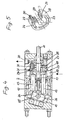
- Fig. 4 eine weitere Ausführungsform des Geräts im Längsschnitt und
- Fig. 5 eine perspektivische Ansicht der Abdichtscheibe gemäß Fig. 4.
- Die Figur 1 zeigt eine derartige Spritzpistole, wobei an dem Handgriff 1 das Pumpengehäuse 2 angeordnet ist, an dem weiterhin ein Motor 3 angebracht ist. Am Pumpengehäuse 2 ist weiterhin ein Ventilgehäuse 4 mit einem Spritzrohr 5 und einer Spritzdüse 6 befestigt. Am Ventilgehäuse 4 ist ein Wasserschlauch 7 angeschlossen, wobei weiterhin an geeigneter Stelle der elektrische Anschluß 8 für den Motor 3 vorgesehen ist. Am Handgriff 1 befindet sich weiterhin ein Handschalter 9.
- Die Figuren 2 und 3 zeigen die besondere Ausführungsform der verwendeten Achsialkolbenpumpe, wobei an den Motor 3 eine feststehende Taumelscheibe 10 ange flanscht ist. An dieser Scheibe 10 ist die Pumpenwelle 11 gelagert, wobei weiterhin an dieser Scheibe 10 das Pumpengehäuse 2 angeflanscht ist. Mit der Welle 11 ist eine angetriebene Scheibe 12 verbunden, in der mehrere Kolben 13, bei dem gezeigten Ausführungsbeispiel sind es vier Kolben 13, verschiebbar geführt sind. Der Kopf 14 der Kolben 13 liegt an der schräggestellten Fläche 15 der Scheibe 10 an. Der Andruck erfolgt mit Hilfe von Federn 16. An der angetriebenen Scheibe 12 ist abgedichtet eine Gleitscheibe 17 befestigt, die an einer am Pumpengehäuse 2 befestigten Dichtscheibe 18 anliegt. Die Dichtscheibe 18 verbindet die Zylinder der Kolben 13 mit dem Saugkanal 19, bzw. dem Druckkanal 20. Zwischen den beiden Kanälen befindet sich ein Überdruckventil 21. An den Druckkanal 20 ist das Spritzrohr 5 und an den Saugkanal 19 der Wasserschlauch 7 angeschlossen. Der Antrieb der Welle 11 für den Motor 3 erfolgt über ein Untersetzungsgetriebe 22.
- In der Dichtscheibe 18 sind kreisförmige Schlitze 23 bzw. 24 angeordnet. Diese Schlitze gewährleisten, daß die Zylinder der Kolben 13 während ihrer Schubbewegung mit dem Auslaß 20 und während ihrer saugenden Bewegung mit dem Anschluß 19 verbunden sind. Durch die Verwendung einer derartigen Dichtscheibe 18 in Verbindung mit der feststehenden Taumelscheibe 10 wird erreicht, daß Ansaug- und Druckventile entfallen können und damit auch eine besonders platzsparende Ausgestaltung der Pumpe möglich ist.
- Bei der in Fig. 4 dargestellten Ausführungsform ist die Pumpenwelle 11 durch die angetriebene Scheibe 12 hindurchgeführt und an einem Kugelgelenk 25 mit der Taumelscheibe 10 verbunden, die am Gehäuse 2 gelagert ist. Am Umfang der Taumelscheibe 10 sind an weiteren Kugelgelenken 26 die Enden der Pumpenkolben 13 angeordnet.
- Damit eine einwandfreie Abdichtung zwischen der Gleitscheibe 17 und der Dichtscheibe 18 gewährleistet ist, ist außen an der Abdichtscheibe 18 eine Haltescheibe 27 angeordnet, wobei mittels dieser Haltescheibe 27 die Abdichtscheibe 18 gegen die Gleitscheibe 17 gedrückt wird. Dazu sind im Bereich des zum Saugkanal 19 gehörenden Ringkanals 23 Druckfedern 28 vorgesehen, die vom Gehäuse 2 gegen die Haltescheibe 27 gedrückt sind. Im Bereich des zum Druckkanal 20 gehörenden Ringkanals 24 sind einzelne Druckbolzen 29 achsial verschiebbar angeordnet, wobei diese Druckbolzen 29 an der Haltescheibe 27 anliegen. Durch den an den Druckbolzen 29 anstehenden Druck wird die Dichtscheibe 18 gegen die Gleitscheibe 17 gedrückt. Weiterhin ist zum Abdichten des nach außen führenden Druckkanals 20 in der Haltescheibe ein Röhrchen 30 angeordnet, das sowohl in der Dichtscheibe 18 als auch im Gehäuse 2 abgedichtet ist. Die Abdichtscheibe 18 weist an ihrem äußeren Umfang eine ballige Fläche 31 auf, so daß eine selbstjustierende Einstellung auf die Gleitscheibe 17 gewährleistet ist.
Claims (8)
1) Hochdruckreinigungsgerät,bestehend aus einem druckerzeugenden Aggregat mit Spritzpistole, dadurch gekennzeichnet, daß das Druckaggregat, bestehend aus einer Mehrfachaxialkolbenpumpe (10, 12, 13) und einem Elektromotor (3) in den Kopf der Spritzpistole einbezogen und das Pumpengehäuse (2) mit dem Pistolengriff (1) verbunden ist.
2) Hochdruckreinigungsgerät nach Anspruch 1, dadurch gekennzeichnet, daß die Pumpe eine feststehende Taumelscheibe (10) aufweist, der eine mit Achsialkolben (13) versehene angetriebene Scheibe (12) zugeordnet ist, wobei die Kolben (13) an der schrägen Fläche (15) der Taumelscheibe (10) geführt sind und daß zwischen der angetriebenen Scheibe (12) und dem Gehäuse (2) mit dem Saug- und Druckanschluß (19, 20) eine Abdichtscheibe (18) angeordnet ist.
3) Hochdruckreinigungsgerät nach Anspruch 1 und 2, dadurch gekennzeichnet, daß die Kolben (13) an der Dichtscheibe (18) mit kreisförmig angeordneten Schlitzen (23, 24) mit ihrer Druck- und Saugseite (19, 20) verbunden sind.
4) Hochdruckreinigungsgerät nach Anspruch 1, dadurch gekennzeichnet, daß die Taumelscheibe (10) drehbar am Gehäuse (2) angeordnet und mittels eines Kugelgelenkes ( 25) mit der Antriebswelle (11) verbunden ist und daß die Kolben (13) an weiteren Kugelgelenken ( 26) an der Taumelscheibe (10) angeordnet sind.
5) Hochdruckreinigungsgerät nach Anspruch 1 bis 4, dadurch gekennzeichnet, daß an der Abdichtscheibe (18) eine Haltescheibe ( 27) anliegt, wobei im Bereich des Ringkanals ( 24) der Druckseite mehrere Druckbolzen ( 29) in der Abdichtscheibe (18) angeordnet und an der Haltescheibe (27) abgestützt sind.
6) Hochdruckreinigungsgerät nach Anspruch 5, dadurch gekennzeichnet, daß zum Abdichten des Druckkanals (20) an der Halte- und Abdichtscheibe (18, 27) ein Röhrchen (30) vorgesehen ist.
7) Hochdruckreinigungsgerät nach Anspruch 5 und 6, dadurch gekennzeichnet, daß die selbstjustierende Abdichtscheibe (18) an ihrem äußeren Umfang ballig ausgebildet ist.
8) Hochdruckreinigungsgerät nach Anspruch 1 bis 7, dadurch gekennzeichnet, daß zwischen der Druckseite (20) und der Saugseite (19) ein Überdruckventil (21) angeordnet ist.
Applications Claiming Priority (2)
| Application Number | Priority Date | Filing Date | Title |
|---|---|---|---|
| DE8713954U DE8713954U1 (de) | 1987-10-17 | 1987-10-17 | Hochdruckreinigungsgerät |
| DE8713954U | 1987-10-17 |
Publications (2)
| Publication Number | Publication Date |
|---|---|
| EP0312862A2 true EP0312862A2 (de) | 1989-04-26 |
| EP0312862A3 EP0312862A3 (de) | 1990-05-16 |
Family
ID=6813203
Family Applications (1)
| Application Number | Title | Priority Date | Filing Date |
|---|---|---|---|
| EP88116715A Withdrawn EP0312862A3 (de) | 1987-10-17 | 1988-10-08 | Hochdruckreinigungsgerät |
Country Status (3)
| Country | Link |
|---|---|
| EP (1) | EP0312862A3 (de) |
| JP (1) | JPH01148356A (de) |
| DE (1) | DE8713954U1 (de) |
Cited By (22)
| Publication number | Priority date | Publication date | Assignee | Title |
|---|---|---|---|---|
| EP0443399A2 (de) * | 1990-02-22 | 1991-08-28 | Franca Bertolini | Handbetätigter Strahlwascher |
| US5071069A (en) * | 1989-09-23 | 1991-12-10 | Black & Decker Inc. | Hand-held high-pressure cleaner |
| EP0464229A1 (de) * | 1990-06-20 | 1992-01-08 | Alfred Kärcher GmbH & Co. | Tragbares Hochdruckreinigungsgerät |
| EP0468081A1 (de) * | 1990-07-27 | 1992-01-29 | Alfred Kärcher GmbH & Co. | Spritzpistole für die Hochdruckreinigung |
| EP0468082A1 (de) * | 1990-07-27 | 1992-01-29 | Alfred Kärcher GmbH & Co. | Spritzpistole für die Hochdruckreinigung |
| GB2247161A (en) * | 1990-08-22 | 1992-02-26 | Shaun Waddingham | Electrical trigger control of water jet |
| EP0476450A1 (de) * | 1990-09-19 | 1992-03-25 | Elektra Beckum Aktiengesellschaft | Axialkolbenpumpe, insbesondere für Wasser-Hochdruckreiniger |
| DE4039926A1 (de) * | 1990-09-19 | 1992-04-09 | Elektra Beckum Lubitz & Co | Axialkolbenpumpe, insbesondere fuer wasser-hochdruckreiniger |
| US5148992A (en) * | 1991-03-19 | 1992-09-22 | Textron Inc. | Washing accessory for a string trimmer |
| EP0521520A1 (de) * | 1991-07-04 | 1993-01-07 | Josef Kränzle | Hochdruckreiniger |
| US7854398B2 (en) | 2005-10-26 | 2010-12-21 | Techtronic Outdoor Products Technology Limited | Hand held pressure washer |
| US8425203B2 (en) | 2008-04-25 | 2013-04-23 | Techtronic Outdoor Products Technology Limited | Portable pressure washer system |
| US8444068B2 (en) | 2005-10-26 | 2013-05-21 | Techtronic Outdoor Products Technology Limited | Dual flow pressure washer |
| CN104564576A (zh) * | 2015-01-15 | 2015-04-29 | 浙江沃尔液压科技有限公司 | 水润滑的高压柱塞泵及手持式高压喷射装置 |
| EP2865451A1 (de) * | 2008-10-22 | 2015-04-29 | Graco Minnesota Inc. | Tragbare luftlose Sprühvorrichtung |
| US9545643B2 (en) | 2008-10-22 | 2017-01-17 | Graco Minnesota Inc. | Portable airless sprayer |
| US10926275B1 (en) | 2020-06-25 | 2021-02-23 | Graco Minnesota Inc. | Electrostatic handheld sprayer |
| US10968899B2 (en) | 2015-11-20 | 2021-04-06 | Positec Power Tools (Suzhou) Co., Ltd. | Pump unit and handheld high pressure washer |
| US10968903B1 (en) | 2020-06-04 | 2021-04-06 | Graco Minnesota Inc. | Handheld sanitary fluid sprayer having resilient polymer pump cylinder |
| US11007545B2 (en) | 2017-01-15 | 2021-05-18 | Graco Minnesota Inc. | Handheld airless paint sprayer repair |
| US11707753B2 (en) | 2019-05-31 | 2023-07-25 | Graco Minnesota Inc. | Handheld fluid sprayer |
| US11986850B2 (en) | 2018-04-10 | 2024-05-21 | Graco Minnesota Inc. | Handheld airless sprayer for paints and other coatings |
Families Citing this family (10)
| Publication number | Priority date | Publication date | Assignee | Title |
|---|---|---|---|---|
| DE4106955A1 (de) * | 1991-03-05 | 1992-09-10 | Kaercher Gmbh & Co Alfred | Hochdruckreinigungsgeraet |
| DE4439209C2 (de) * | 1994-11-03 | 1996-05-02 | Eberhard Dipl Ing Weber | Hochruck-Reinigungspistole mit integriertem Kolbenaggregat |
| DE102008019524A1 (de) * | 2008-04-09 | 2009-10-15 | Alfred Kärcher Gmbh & Co. Kg | Hochdruckreinigungsgerät |
| US9016599B2 (en) | 2009-05-07 | 2015-04-28 | Graco Minnesota Inc. | Wobble assembly for fluid pumping mechanism |
| US8651402B2 (en) | 2009-11-17 | 2014-02-18 | Black & Decker Inc. | Adjustable nozzle tip for paint sprayer |
| CN203018246U (zh) | 2009-11-17 | 2013-06-26 | 布莱克和戴克公司 | 涂料喷涂器 |
| US8413911B2 (en) | 2009-11-17 | 2013-04-09 | Black & Decker Inc. | Paint sprayer |
| US8740111B2 (en) | 2009-11-17 | 2014-06-03 | Black & Decker Inc. | Paint sprayer |
| US8550376B2 (en) | 2009-11-17 | 2013-10-08 | Black & Decker Inc. | Paint sprayer |
| WO2011062992A1 (en) | 2009-11-17 | 2011-05-26 | Black & Decker Inc. | Quick release mechanism for paint sprayer |
Citations (7)
| Publication number | Priority date | Publication date | Assignee | Title |
|---|---|---|---|---|
| DE593597C (de) * | 1931-01-28 | 1934-09-10 | Viktor Jereczek | Fluessigkeitspumpe |
| US2195929A (en) * | 1937-01-25 | 1940-04-02 | Bosch Gmbh Robert | Hand spraying implement |
| US3208397A (en) * | 1963-06-19 | 1965-09-28 | Lehrer Alexander | Quiet hydraulic pump |
| FR1573048A (de) * | 1968-02-26 | 1969-07-04 | ||
| CH513335A (de) * | 1970-01-10 | 1971-09-30 | Bosch Gmbh Robert | Axialkolbenmaschine |
| FR2338397A1 (fr) * | 1976-01-13 | 1977-08-12 | Thoma Jean | Perfectionnements relatifs a des pompes et moteurs hydrauliques rotatifs a pistons axiaux |
| DE3248622A1 (de) * | 1982-12-30 | 1984-07-12 | Alfred Kärcher GmbH & Co, 7057 Winnenden | Hochdruckreinigungsgeraet |
Family Cites Families (7)
| Publication number | Priority date | Publication date | Assignee | Title |
|---|---|---|---|---|
| US2013639A (en) * | 1932-04-07 | 1935-09-03 | Bosch Robert | Apparatus for spraying liquids such as paints, varnishes, or the like |
| US2540357A (en) * | 1946-03-18 | 1951-02-06 | Stanley William | Spray gun |
| AT202407B (de) * | 1957-08-02 | 1959-03-10 | Vertriebs Ges Ing Wagner | Hochdruckpistole für Fett und Öl |
| DE6904669U (de) * | 1969-02-07 | 1969-07-24 | Josef Wagner | Foerderaggregat fuer farbspritzanlagen |
| DE2433841A1 (de) * | 1974-07-15 | 1976-02-05 | Kovats Peter J Dipl Volksw | Gleichstrom- und/oder druckluft-antriebssystem fuer tragbare hand-hochdruckspritzpistolen des airless-prinzips mit regulierbarer druckleistung |
| GB1576075A (en) * | 1976-04-12 | 1980-10-01 | Union Carbide Australia | Portable sprying device |
| DE2623324C2 (de) * | 1976-05-25 | 1983-01-05 | Wella Ag, 6100 Darmstadt | Handgerät zum Versprühen von Flüssigkeit |
-
1987
- 1987-10-17 DE DE8713954U patent/DE8713954U1/de not_active Expired
-
1988
- 1988-10-08 EP EP88116715A patent/EP0312862A3/de not_active Withdrawn
- 1988-10-17 JP JP63259617A patent/JPH01148356A/ja active Pending
Patent Citations (7)
| Publication number | Priority date | Publication date | Assignee | Title |
|---|---|---|---|---|
| DE593597C (de) * | 1931-01-28 | 1934-09-10 | Viktor Jereczek | Fluessigkeitspumpe |
| US2195929A (en) * | 1937-01-25 | 1940-04-02 | Bosch Gmbh Robert | Hand spraying implement |
| US3208397A (en) * | 1963-06-19 | 1965-09-28 | Lehrer Alexander | Quiet hydraulic pump |
| FR1573048A (de) * | 1968-02-26 | 1969-07-04 | ||
| CH513335A (de) * | 1970-01-10 | 1971-09-30 | Bosch Gmbh Robert | Axialkolbenmaschine |
| FR2338397A1 (fr) * | 1976-01-13 | 1977-08-12 | Thoma Jean | Perfectionnements relatifs a des pompes et moteurs hydrauliques rotatifs a pistons axiaux |
| DE3248622A1 (de) * | 1982-12-30 | 1984-07-12 | Alfred Kärcher GmbH & Co, 7057 Winnenden | Hochdruckreinigungsgeraet |
Cited By (37)
| Publication number | Priority date | Publication date | Assignee | Title |
|---|---|---|---|---|
| US5071069A (en) * | 1989-09-23 | 1991-12-10 | Black & Decker Inc. | Hand-held high-pressure cleaner |
| EP0443399A3 (en) * | 1990-02-22 | 1992-09-02 | Franca Bertolini | Hand-held jet washer |
| EP0443399A2 (de) * | 1990-02-22 | 1991-08-28 | Franca Bertolini | Handbetätigter Strahlwascher |
| EP0464229A1 (de) * | 1990-06-20 | 1992-01-08 | Alfred Kärcher GmbH & Co. | Tragbares Hochdruckreinigungsgerät |
| EP0468081A1 (de) * | 1990-07-27 | 1992-01-29 | Alfred Kärcher GmbH & Co. | Spritzpistole für die Hochdruckreinigung |
| EP0468082A1 (de) * | 1990-07-27 | 1992-01-29 | Alfred Kärcher GmbH & Co. | Spritzpistole für die Hochdruckreinigung |
| GB2247161A (en) * | 1990-08-22 | 1992-02-26 | Shaun Waddingham | Electrical trigger control of water jet |
| EP0476450A1 (de) * | 1990-09-19 | 1992-03-25 | Elektra Beckum Aktiengesellschaft | Axialkolbenpumpe, insbesondere für Wasser-Hochdruckreiniger |
| DE4039926A1 (de) * | 1990-09-19 | 1992-04-09 | Elektra Beckum Lubitz & Co | Axialkolbenpumpe, insbesondere fuer wasser-hochdruckreiniger |
| US5148992A (en) * | 1991-03-19 | 1992-09-22 | Textron Inc. | Washing accessory for a string trimmer |
| EP0521520A1 (de) * | 1991-07-04 | 1993-01-07 | Josef Kränzle | Hochdruckreiniger |
| DE4122191A1 (de) * | 1991-07-04 | 1993-01-07 | Josef Kraenzle | Hochdruckreiniger |
| US7854398B2 (en) | 2005-10-26 | 2010-12-21 | Techtronic Outdoor Products Technology Limited | Hand held pressure washer |
| US8444068B2 (en) | 2005-10-26 | 2013-05-21 | Techtronic Outdoor Products Technology Limited | Dual flow pressure washer |
| US8425203B2 (en) | 2008-04-25 | 2013-04-23 | Techtronic Outdoor Products Technology Limited | Portable pressure washer system |
| US9545643B2 (en) | 2008-10-22 | 2017-01-17 | Graco Minnesota Inc. | Portable airless sprayer |
| US9914141B2 (en) | 2008-10-22 | 2018-03-13 | Graco Minnesota, Inc. | Portable airless sprayer |
| US9517479B2 (en) | 2008-10-22 | 2016-12-13 | Graco Minnesota Inc. | Portable airless sprayer |
| US11446690B2 (en) | 2008-10-22 | 2022-09-20 | Graco Minnesota Inc. | Portable airless sprayer |
| US9604235B2 (en) | 2008-10-22 | 2017-03-28 | Graco Minnesota Inc. | Portable airless sprayer |
| US9604234B2 (en) | 2008-10-22 | 2017-03-28 | Graco Minnesota Inc. | Portable airless sprayer |
| US11623234B2 (en) | 2008-10-22 | 2023-04-11 | Graco Minnesota Inc. | Portable airless sprayer |
| US11446689B2 (en) | 2008-10-22 | 2022-09-20 | Graco Minnesota Inc. | Portable airless sprayer |
| US10919060B2 (en) | 2008-10-22 | 2021-02-16 | Graco Minnesota Inc. | Portable airless sprayer |
| US11779945B2 (en) | 2008-10-22 | 2023-10-10 | Graco Minnesota Inc. | Portable airless sprayer |
| US11759808B1 (en) | 2008-10-22 | 2023-09-19 | Graco Minnesota Inc. | Portable airless sprayer |
| EP2865451A1 (de) * | 2008-10-22 | 2015-04-29 | Graco Minnesota Inc. | Tragbare luftlose Sprühvorrichtung |
| CN104564576B (zh) * | 2015-01-15 | 2017-10-20 | 沃尔科技有限公司 | 水润滑的高压柱塞泵及手持式高压喷射装置 |
| CN104564576A (zh) * | 2015-01-15 | 2015-04-29 | 浙江沃尔液压科技有限公司 | 水润滑的高压柱塞泵及手持式高压喷射装置 |
| USRE49589E1 (en) | 2015-11-20 | 2023-07-25 | Positec Power Tools (Suzhou) Co., Ltd | Pump unit and handheld high pressure washer |
| US10968899B2 (en) | 2015-11-20 | 2021-04-06 | Positec Power Tools (Suzhou) Co., Ltd. | Pump unit and handheld high pressure washer |
| US11007545B2 (en) | 2017-01-15 | 2021-05-18 | Graco Minnesota Inc. | Handheld airless paint sprayer repair |
| US11986850B2 (en) | 2018-04-10 | 2024-05-21 | Graco Minnesota Inc. | Handheld airless sprayer for paints and other coatings |
| US11707753B2 (en) | 2019-05-31 | 2023-07-25 | Graco Minnesota Inc. | Handheld fluid sprayer |
| US10968903B1 (en) | 2020-06-04 | 2021-04-06 | Graco Minnesota Inc. | Handheld sanitary fluid sprayer having resilient polymer pump cylinder |
| US11738358B2 (en) | 2020-06-25 | 2023-08-29 | Graco Minnesota Inc. | Electrostatic handheld sprayer |
| US10926275B1 (en) | 2020-06-25 | 2021-02-23 | Graco Minnesota Inc. | Electrostatic handheld sprayer |
Also Published As
| Publication number | Publication date |
|---|---|
| DE8713954U1 (de) | 1987-12-03 |
| JPH01148356A (ja) | 1989-06-09 |
| EP0312862A3 (de) | 1990-05-16 |
Similar Documents
| Publication | Publication Date | Title |
|---|---|---|
| EP0312862A2 (de) | Hochdruckreinigungsgerät | |
| CH661451A5 (de) | Pumpe fuer zerstaeuber von fluessigkeiten. | |
| DE2751633A1 (de) | Schleifgeraet mit absaugvorrichtung | |
| DE2349717C3 (de) | Hubwagen für Fahrzeuge | |
| DE3133111A1 (de) | Druckbeschaffungseinrichtung | |
| DE2712552B1 (de) | Magnetkolbenpumpe zum Foerdern von Fluiden | |
| DE3706351A1 (de) | Durch einen druckluft-kolbenmotor angetriebene fluessigkeits-kolbenpumpe | |
| DE3042328A1 (de) | Kolbenpumpe | |
| DE1653355B2 (de) | Selbsttaetige steuerung fuer einen druckluftantrieb einer fluessigkeits- membranpumpe | |
| EP0363627A2 (de) | Einrichtung zur Förderung von Farben | |
| DE1528582A1 (de) | Pumpe | |
| DE2524017A1 (de) | Hydraulischer druckzylinder und einrichtung zur druckerzeugung | |
| EP0464229A1 (de) | Tragbares Hochdruckreinigungsgerät | |
| DE8105492U1 (de) | Pneumohydraulisches versorgungsaggregat mit einem leistung erzeugenden motor | |
| DE9416535U1 (de) | Handgerät zum Stanzen von Löchern | |
| DE10191359B4 (de) | Medienpumpe | |
| DE2934301A1 (de) | Vorrichtung zum aufladen von druckspeichern mit hochkomprimiertem gas in hydraulikanlagen. | |
| DE2652346C3 (de) | ||
| EP0892174A2 (de) | Pumpenkopf für eine Hubkolbenpumpe | |
| DE3632717A1 (de) | Aggregat mit einer membrane | |
| CH666939A5 (de) | Hochdruckfoerdervorrichtung. | |
| DE7619113U1 (de) | Kolbenpumpe zur verwendung mit einer druckoel fuehrenden hydraulikanlage | |
| DE1292004B (de) | Transportables, motorisch angetriebenes Fluessigkeitshochdruckkolbenpumpenaggregat | |
| DE331854T1 (de) | Fluessigkeitsbetaetigungseinrichtung fuer den antrieb einer drehwelle. | |
| DE607032C (de) | Fluessigkeitsgetriebe mit einer antreibenden Zahnradpumpe und einem wechselseitig angetriebenen Arbeitskolben |
Legal Events
| Date | Code | Title | Description |
|---|---|---|---|
| PUAI | Public reference made under article 153(3) epc to a published international application that has entered the european phase |
Free format text: ORIGINAL CODE: 0009012 |
|
| AK | Designated contracting states |
Kind code of ref document: A2 Designated state(s): AT BE CH DE ES FR GB GR IT LI LU NL SE |
|
| PUAL | Search report despatched |
Free format text: ORIGINAL CODE: 0009013 |
|
| AK | Designated contracting states |
Kind code of ref document: A3 Designated state(s): AT BE CH DE ES FR GB GR IT LI LU NL SE |
|
| STAA | Information on the status of an ep patent application or granted ep patent |
Free format text: STATUS: THE APPLICATION IS DEEMED TO BE WITHDRAWN |
|
| 18D | Application deemed to be withdrawn |
Effective date: 19901117 |