EP0312774A2 - Appareil de dépôt de ruban de fibres d'un carde avec un entraînement électronique - Google Patents
Appareil de dépôt de ruban de fibres d'un carde avec un entraînement électronique Download PDFInfo
- Publication number
- EP0312774A2 EP0312774A2 EP19880115167 EP88115167A EP0312774A2 EP 0312774 A2 EP0312774 A2 EP 0312774A2 EP 19880115167 EP19880115167 EP 19880115167 EP 88115167 A EP88115167 A EP 88115167A EP 0312774 A2 EP0312774 A2 EP 0312774A2
- Authority
- EP
- European Patent Office
- Prior art keywords
- sliver
- feed rollers
- rollers
- stick according
- electric motor
- Prior art date
- Legal status (The legal status is an assumption and is not a legal conclusion. Google has not performed a legal analysis and makes no representation as to the accuracy of the status listed.)
- Granted
Links
- 238000009960 carding Methods 0.000 title claims abstract description 5
- 238000011144 upstream manufacturing Methods 0.000 claims description 4
- 238000006073 displacement reaction Methods 0.000 claims 1
- 230000009467 reduction Effects 0.000 description 8
- 230000008859 change Effects 0.000 description 6
- 230000007423 decrease Effects 0.000 description 6
- 230000008878 coupling Effects 0.000 description 4
- 238000010168 coupling process Methods 0.000 description 4
- 238000005859 coupling reaction Methods 0.000 description 4
- 230000005540 biological transmission Effects 0.000 description 3
- 230000001419 dependent effect Effects 0.000 description 2
- 238000013461 design Methods 0.000 description 2
- 238000011161 development Methods 0.000 description 2
- 238000009434 installation Methods 0.000 description 2
- 238000013519 translation Methods 0.000 description 2
- 230000001133 acceleration Effects 0.000 description 1
- 230000008901 benefit Effects 0.000 description 1
- 230000033228 biological regulation Effects 0.000 description 1
- 238000010276 construction Methods 0.000 description 1
- 230000003247 decreasing effect Effects 0.000 description 1
- 238000010586 diagram Methods 0.000 description 1
- 238000003780 insertion Methods 0.000 description 1
- 230000037431 insertion Effects 0.000 description 1
- 238000012423 maintenance Methods 0.000 description 1
- 230000009347 mechanical transmission Effects 0.000 description 1
- 230000004044 response Effects 0.000 description 1
- 238000012549 training Methods 0.000 description 1
- 238000004804 winding Methods 0.000 description 1
Images


Classifications
-
- D—TEXTILES; PAPER
- D01—NATURAL OR MAN-MADE THREADS OR FIBRES; SPINNING
- D01G—PRELIMINARY TREATMENT OF FIBRES, e.g. FOR SPINNING
- D01G15/00—Carding machines or accessories; Card clothing; Burr-crushing or removing arrangements associated with carding or other preliminary-treatment machines
- D01G15/02—Carding machines
- D01G15/12—Details
- D01G15/46—Doffing or like arrangements for removing fibres from carding elements; Web-dividing apparatus; Condensers
- D01G15/64—Drafting or twisting apparatus associated with doffing arrangements or with web-dividing apparatus
-
- B—PERFORMING OPERATIONS; TRANSPORTING
- B65—CONVEYING; PACKING; STORING; HANDLING THIN OR FILAMENTARY MATERIAL
- B65H—HANDLING THIN OR FILAMENTARY MATERIAL, e.g. SHEETS, WEBS, CABLES
- B65H54/00—Winding, coiling, or depositing filamentary material
- B65H54/76—Depositing materials in cans or receptacles
- B65H54/80—Apparatus in which the depositing device or the receptacle is rotated
-
- B—PERFORMING OPERATIONS; TRANSPORTING
- B65—CONVEYING; PACKING; STORING; HANDLING THIN OR FILAMENTARY MATERIAL
- B65H—HANDLING THIN OR FILAMENTARY MATERIAL, e.g. SHEETS, WEBS, CABLES
- B65H2701/00—Handled material; Storage means
- B65H2701/30—Handled filamentary material
- B65H2701/31—Textiles threads or artificial strands of filaments
Definitions
- the invention relates to a jug (sliver insertion device) on a card, draw frame, carding machine or the like with an electromotive drive device which drives sliver feed rollers arranged in the region of a sliver inlet opening and sliver feed rollers upstream of the sliver inlet opening, as well as drive-less sliver guide rollers between sliver feed rollers and sliver delivery rollers, the drive speeds of the sliver feed rollers and of the belt feed rollers are in an adjustable relationship to each other.
- Pitcher sticks of the type mentioned are known. They are preceded by a card that feeds the sliver at a certain speed.
- the card has the above-mentioned sliver delivery rollers, between which the sliver is passed.
- the belt driven by the belt feed rollers runs via subsequent belt guide rollers to the above-mentioned sliver inlet opening, which is followed by the belt feed rollers. From there, the tape is placed in an orderly jug in the jug.
- the mounting position of the can stock is fixed relative to the card. It can only be changed in position with considerable effort. Depending on the type and installation type of the machine supplying the sliver, an adjustment of the installation position of the can stick relative to the card is desired.
- Another problem with the known solutions is the threading of the sliver into the sliver inlet opening (sliver funnel) of the can stick. This creates a belt loop, which is only gradually broken down by the translation between the belt feed rollers and the belt feed rollers. During this time of dismantling, the sliver is not properly guided, so that the card cannot work at high speed.
- the invention is therefore based on the object of providing a jug with an electromotive drive device of the type mentioned at the outset which, with a simple design, permits problem-free sliver transport.
- only relatively small drive powers are required and, after the threading phase of the sliver, it can be driven very quickly at maximum speed.
- the tape feed rollers are driven by an electric motor and that the speed of the tape feed rollers is detected by a sensor of an electrical control device which controls the speed of the electric motor depending on the sensor measured value.
- This training completely dispenses with complex mechanical gears between the tape feed rollers and the tape feed rollers. Rather, each type of roller has its own drive, so that relatively small motors are sufficient in terms of performance. Small drive powers result in relatively low investment costs.
- the speed ratio between the tape feed rollers and the tape feed rollers is controlled by the respective speed of the tape feed rollers. According to the invention, the coupling of these two drives is implemented electronically.
- the strip delivery rollers are connected to a sensor which emits an output signal in accordance with the speed in each case.
- This output signal is fed to an electrical control device which is connected to the electric motor for driving the tape feed rollers.
- the speed of the motor to be controlled can be set on the control device.
- the set speed ratio between the tape feed rollers and the tape feed rollers is maintained in every operating state in that the speed control of the electric motor carried out by the control device takes place as a function of the output signal (sensor measured value) of the sensor.
- the arrangement can be designed as a controller or as a regulator be.
- the respective actual state is determined and compared with a set target value. If there is a discrepancy between the actual and the target value, the speed of the electric motor controlled by the control device is changed until the desired target value has been reached. In the case of a control, on the other hand, occurring disturbance variables that can cause a deviation from the intended speed ratio are not taken into account.
- the solution according to the invention has the advantage that no mechanical transmission elements but only an electrical connection is required between the card and the cane. This makes it possible to place the two machine components at any desired location depending on the space available and the requirements for the belt guide.
- the components can be connected to one another via an electrical plug connection, so that assembly or disassembly is possible at any time without great effort.
- the electric motor driving the tape feed rollers rotates current motor, which is connected to a frequency converter controlled by the sensor.
- the speed of the three-phase motor can be set economically in a simple manner by means of the frequency converter, the control information for the speed setting coming from the sensor, which delivers a control signal as a function of the speed of the belt feed rollers.
- the electric motor driving the belt feed rollers can be designed, for example, as an AC motor or as a DC motor.
- the senor is designed as a tachometer generator coupled to the belt delivery rollers.
- the tachometer generator supplies an output voltage which is dependent on the speed of the strip supply rollers and is supplied as a control voltage to the frequency converter, which outputs a corresponding output frequency for operating the three-phase motor of the strip feed rollers. The speed of this three-phase motor is thus controlled via the frequency.
- the arrangement can be such that at least one of the ribbon guide rollers is displaceable depending on the ribbon tension to form a sliver loop and that the respective shift position is detected by an electrical measuring device and fed to the frequency converter as a control variable for fine-tuning the speed ratio.
- the electrical measuring device responds, which supplies a control variable to the frequency converter to eliminate the disturbance, as a result of which the output frequency of the frequency converter is increased or decreased accordingly.
- the three-phase motor controlling the strip feed rollers experiences a corresponding increase or decrease in speed, so that the loop that is formed is restored and a stable operating state is restored.
- the tape guide roller assigned to the measuring device is preferably mounted on a dancer device.
- the dancer device allows the belt guide roller to be displaced in such a way that an increase or decrease in the size of the sliver is followed.
- the tape guide roller is arranged on an end region of a dancer arm, which carries an adjustable counterweight at its other end region and is pivotably mounted between its end regions, the pivot axis being connected to a rotary angle encoder forming the measuring device.
- the rotary encoder can preferably be designed as a potentiometer. Depending on the position of the counterweight, a correspondingly large sliver loop will occur during stationary operation. As soon as a change in the loop size occurs due to certain disturbance variables, the dancer arm is shifted (swiveling), as a result of which the position of the rotary encoder is changed. If this rotary encoder is a potentiometer, its resistance value changes, which is detected by the frequency converter. In response to this change in resistance, the frequency converter makes a change in its output voltage frequency, so that a corresponding strip tension is set via the resulting change in speed of the belt feed roller motor, which restores the normal operating state.
- the measuring device is connected to the frequency converter via a PI controller.
- the control behavior of this type of controller enables particularly quick and vibration-free intervention.
- a turntable is provided for the rotation of a sliver receiving the sliver, which is driven by a belt drive gear with the electric motor of the tape feed rollers.
- the sliver inlet opening of the jug can runs on a circular path above the jug, so that the sliver entering the jug is deposited in a circle. Superimposed on this movement, the jug rotates about the axis of the turntable, so that the jug can be loaded very evenly.
- the electric motor driving the tape feed rollers preferably has a second shaft output, to which a reduction gear is preferably flanged, the drive shaft of which is connected to the belt drive gear.
- the turntable is coupled to a separate electric motor.
- This electric motor can preferably be a speed-controlled three-phase motor.
- the three-phase motor is coupled for speed control with the electric motor of the tape feed rollers via an electronic adjusting device, the speed ratio of both motors being adjustable.
- the invention is not limited to the use of three-phase motors and the use of frequency converters, since for example direct-current motors can also be used, the speed of which can be varied by means of corresponding control devices.
- direct-current motors can also be used, the speed of which can be varied by means of corresponding control devices.
- single-phase AC motors is also conceivable.
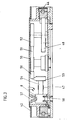
- Fig. 1 shows a can 2 on an upstream card 1 with a drive device 3, the tape feed rollers 4, tape guide rollers 5, 6 and 7 and tape feed rollers 8 and associated drives 9.
- a sliver 10 is transported and placed in an order in a can 11 of the can stick 2.
- the two sliver feed rollers 4 with shafts 12 running parallel to one another are parallel to each other at a small distance, so that a clamping gap for the sliver 10 remains between the sliver feed rollers 4.
- One of the belt feed rollers 4 is connected via the shaft 12 to an electric motor 13 of the card 1 belonging to the drive 9, while the other belt feed roller 4 is connected via its shaft 12 to a sensor 14 which is designed as a tachometer generator 15.
- the sliver 10 runs from the sliver delivery rollers 4 to a sliver guide device 16 which is fastened to the machine frame of the can 2.
- the tape guide device 16 has a foot 17 on which a support arm 18 befe is increasing. At one end of the support arm 18, the tape guide roller 5 and at the other end, the tape guide roller 7 is rotatably arranged.
- a dancer device 20 is mounted on the support arm 18.
- a support strut 21 is attached to the sleeve 19, at the end of which a dancer arm 22 is pivotally mounted.
- the dancer arm 22 has the tape guide roller 6 at one end region 23 and an adjustable counterweight 25 at its other end region 24.
- the sliver 10 runs over the sliver guide rollers 5, 6 and 7 and is fed from above to a sliver inlet opening 26 of the can 2.
- the machine frame of the jug 2 has a foot frame 25 on which a support column 28 is arranged. Furthermore, a receiving chamber 29 is formed, in which the can 11 is arranged. A reduction gear 30 is arranged on the support column 28, to which an electric motor 31 belonging to the drive 9 is flanged.
- the vertically arranged electric motor 31 is designed as a three-phase motor 32 and has two shaft outputs 33 and 34 located opposite one another.
- the lower, second shaft output 34 is connected to the reduction gear 30, the output shaft 35 of which is coupled to a shaft 36 which connects the hollow support column 28 enforced.
- the lower end of the shaft 36 is mounted in the foot frame 27 and provided with a pulley 37.
- the pulley 37 belongs to a belt drive gear 38 which is arranged in the interior of the foot frame 27.
- the belt drive gear 38 also has a further, larger diameter pulley 39 which is connected to a turntable 40 on which the can 11 is located.
- the pulleys 37 and 39 are connected to each other by means of a belt loop 41.
- the upper, first shaft output 33 of the three-phase motor 32 projects into a housing 42 which receives parts of the drive device 3 for the sliver 10.
- the housing 42 in the head of the can 2 houses a belt wheel 43 which is arranged on the first shaft output 33 of the three-phase motor 32 and is connected via a belt 44 to a plate-shaped rotary housing 45.
- a friction wheel 48 is mounted on the bottom 47 of the rotary housing 45 and, when the rotary housing 45 rotates, rolls on an annular body 49 which is arranged in a fixed manner in the head of the can stick 2.
- three pulleys 50 are rotatably installed on the bottom 7 of the rotary housing 45, which are connected to one another by means of a belt loop 51, the belt loop 51 also wrapping around a drive flange 52 of the friction wheel 48.
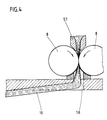
- the exact belt guide is shown in FIG. 2. Between the upper and the lower pulley 50, in the position according to FIG.
- a pulley 53 which has a horizontal axis 54.
- further pulleys 55 and 56 are provided, which also have horizontal axes of rotation.
- the belt loop 51 is rotated by 90 ° due to the arrangement of the pulley in the area of the pulley 53, so that a rotary movement of the rotary housing 45 in the direction of the arrow x results in a rotation of the friction wheel 48 in the direction y, whereby the horizontal axis 54 via the belt loop 51 the pulley 53 is rotated.
- the axis 54 leads to one of the tape feed rollers 8, which is opposite another tape feed roller 8 with the axis of rotation running parallel to the former.
- the sliver inlet opening 26 is arranged, which - as shown in FIG. 3- has a nozzle 57.
- a guide tube 58 is provided beneath the band feed rollers 8, which extends through the bottom 47 of the rotary housing 45 and guides the sliver 10 transported by the band feed rollers 8 into the interior of the can 11.
- the electric motor 13 is electronically coupled to the electric motor 31, so that a speed difference between the sliver feed rollers 4 and the sliver feed rollers 8 is set such that in particular an elongation of the sliver 10 between card 1 and sliver inlet opening 26 is compensated.
- Fig. 6 the drive principle is shown schematically. It can be seen there that the sliver 10 running between the sliver feed rollers 4 is fed to the sliver feed rollers 8 via the sliver guide rollers 5, 6 and 7.
- the tachometer generator 15 connected to one of the strip delivery rollers 4 via the shaft 12 is connected to a frequency converter 60 via a line 59.
- the frequency converter 60 has an output line 61 which is connected to the three-phase motor 32.
- the pivot axis 62 of the dancer arm 22 is connected to an electrical measuring device 63, which is designed as an angle encoder 64.
- the rotary angle transmitter 64 thus registers the angular position of the dancer arm 22.
- the rotary angle transmitter 64 preferably consists of a potentiometer 65. This potentiometer 65 (not shown in FIG. 6) is connected via an electrical line 66 to a PI controller 67 which is connected on the output side to the frequency converter 60 via a line 68.
- the reduction gear 30 and a power transmission path 69 are shown, which transmits the motor power of the three-phase motor 32 to the tape feed rollers 8.
- the power transmission link 69 is composed of the belt wheel 43, the rotary housing 45 and the friction wheel 48 and the pulleys 50, 53, 55 and 56 and the associated belts, etc.
- the arrangement is now such that a voltage dependent on the speed of the sliver delivery rollers 4 is present on the line 59 during operation due to the rotary entrainment of the tachometer generator 15 and is fed to the frequency converter 60.
- the frequency converter 60 Depending on the output voltage of the tachometer generator 15, the frequency converter 60 generates a supply voltage for the three-phase motor 32 on the line 61.
- the frequency of this supply voltage depends on the size of the output voltage of the tachometer generator 15. The greater the output voltage of the tachometer generator 15, the greater the frequency of the supply voltage of the three-phase motor 32 and thus also its speed. If the output voltage of the tachometer generator 15 decreases, the frequency of the supply voltage for the three-phase motor 32 decreases in a corresponding manner. This results in a speed reduction of the three-phase motor 32.
- the speed ratio between tape feed rollers 4 and tape feed rollers 8 can be determined by means of an adjusting device, not shown.
- the dancer arm 32 is pivoted accordingly, whereby the potentiometer 65 is adjusted.
- the change in the resistance value of the potentiometer 65 is conducted via line 66 to the PI controller 67, which is connected on the output side to the frequency converter 60 via line 68.
- the arrangement is now such that an increase in the loop of the sliver 10 between the tape guide rollers 5 and 7 leads to a potentiometer adjustment, which increases the frequency of the frequency converter, so that the supply voltage frequency of the three-phase motor 32 increases, so that its speed is increased.
- the size of the loop is reduced, as a result of which the dancer arm 22 continuously pivots and, via the potentiometer 65, the frequency converter 60 is controlled in such a way that the output frequency of the frequency converter 60 is also reduced until the normal preset speed difference between belt feed rollers 4 and tape feed rollers 8 is restored.
- the entire arrangement can be designed as a control loop, so that deviations from a predetermined setpoint of the sliver transport are corrected.
- the device according to the invention makes it possible to keep the sliver tension of the sliver 10 constant, so that an essentially trouble-free operation can be carried out.
- the turntable 40 can also have its own, separate ten electric motor are driven.
- This electric motor is preferably designed as a speed-controlled three-phase motor. It is coupled to its speed control with the electric motor of the tape feed rollers via an electronic control device, so that the speed ratio of both motors can be adjusted.
- the mechanical connection between the three-phase motor 32 and the turntable 40 described in the previous exemplary embodiment can be omitted.
- the electronically adjustable transmission ratio between the speeds of the tape feed rollers 4 and the tape feed rollers 8 can be adapted to the respective conditions.
- the gear ratio By changing the gear ratio, the distance Z of the belt layers in the can 11 can be varied.
- the can filling must therefore be optimized on site. Optimal loading of the can 11 with the sliver 10 is thus possible.
Landscapes
- Engineering & Computer Science (AREA)
- Textile Engineering (AREA)
- Preliminary Treatment Of Fibers (AREA)
- Telephone Function (AREA)
- Coupling Device And Connection With Printed Circuit (AREA)
- Spinning Or Twisting Of Yarns (AREA)
Priority Applications (1)
| Application Number | Priority Date | Filing Date | Title |
|---|---|---|---|
| AT88115167T ATE96405T1 (de) | 1987-10-12 | 1988-09-16 | Kannenstock an karde mit elektronischer antriebsvorrichtung. |
Applications Claiming Priority (2)
| Application Number | Priority Date | Filing Date | Title |
|---|---|---|---|
| DE3734425A DE3734425C2 (de) | 1987-10-12 | 1987-10-12 | Kannenstock an Karde mit elektromotorischer Antriebsvorrichtung |
| DE3734425 | 1987-10-12 |
Publications (3)
| Publication Number | Publication Date |
|---|---|
| EP0312774A2 true EP0312774A2 (fr) | 1989-04-26 |
| EP0312774A3 EP0312774A3 (fr) | 1991-07-03 |
| EP0312774B1 EP0312774B1 (fr) | 1993-10-27 |
Family
ID=6338119
Family Applications (1)
| Application Number | Title | Priority Date | Filing Date |
|---|---|---|---|
| EP88115167A Expired - Lifetime EP0312774B1 (fr) | 1987-10-12 | 1988-09-16 | Appareil de dépôt de ruban de fibres d'un carde avec un entraînement électronique |
Country Status (4)
| Country | Link |
|---|---|
| EP (1) | EP0312774B1 (fr) |
| AT (1) | ATE96405T1 (fr) |
| DE (2) | DE3734425C2 (fr) |
| ES (1) | ES2046265T3 (fr) |
Cited By (9)
| Publication number | Priority date | Publication date | Assignee | Title |
|---|---|---|---|---|
| WO1992004266A2 (fr) * | 1990-09-07 | 1992-03-19 | Officina Meccanica Mec Di G.Ramella & C. S.A.S. | Dispositif d'empilage de rubans de fibres |
| EP0671355A2 (fr) * | 1994-03-09 | 1995-09-13 | Maschinenfabrik Rieter Ag | Stockage de ruban de fibres |
| FR2723577A1 (fr) * | 1994-08-11 | 1996-02-16 | Truetzschler Gmbh & Co Kg | Procede et dispositif pour le depot d'un ruban de fibres textiles dans un pot a ruban, en particulier sur une carde ou un banc d'etirage |
| FR2725433A1 (fr) * | 1994-08-11 | 1996-04-12 | Truetzschler Gmbh & Co Kg | Procede et dispositif de depot d'un ruban de fibres textiles dans un pot a rubans, en particulier sur un banc d'etirage |
| FR2733770A1 (fr) * | 1995-05-02 | 1996-11-08 | Dumortier Peignage | Installation pour la collecte du ruban de fibres textiles a la sortie d'une machine de cardage |
| EP0768399A1 (fr) * | 1995-10-16 | 1997-04-16 | F.LLi Marzoli & C. S.p.A. | Dispositif automatique de réglage et de contrÔle de la tension d'un ruban de fibres transféré d'une unité d'étirage de la carde au dispositif d'empotage de ruban |
| WO1999058749A1 (fr) * | 1998-05-13 | 1999-11-18 | Maschinenfabrik Rieter Ag | Machine traitant une matiere textile et dotee d'un bac d'etirage |
| JP2008202211A (ja) * | 1996-06-29 | 2008-09-04 | Truetzschler Gmbh & Co Kg | カード出口にデリベリローラを有するウェブファンネルを設けたカードにおける装置 |
| CN108454082A (zh) * | 2018-04-04 | 2018-08-28 | 洛阳理工学院 | 一种弯管缠绕机防腐复合带的缠绕包覆装置 |
Families Citing this family (8)
| Publication number | Priority date | Publication date | Assignee | Title |
|---|---|---|---|---|
| DE4319631C2 (de) * | 1993-06-15 | 1996-03-28 | Wirkbau Textilmasch Gmbh | Antriebssystem an Deckelkarden mit mindestens zwei Kardiersystemen |
| DE4340643C2 (de) * | 1993-11-29 | 1996-09-05 | Chemnitzer Spinnereimaschinen | Antriebssystem für mehrsystemige Deckelkarden |
| DE10116944A1 (de) * | 2001-04-05 | 2002-10-10 | Truetzschler Gmbh & Co Kg | Vorrichtung an einer Karde zum Füllen einer Kanne mit länglichem Querschnitt |
| DE10205061A1 (de) * | 2002-02-07 | 2003-08-14 | Truetzschler Gmbh & Co Kg | Vorrichtung an einer Spinnereivorbereitungsmaschine, insbesondere Strecke oder Karde, bei der am Ausgang ein Faserband abgegeben und abgelegt wird |
| US7748658B2 (en) | 2002-02-07 | 2010-07-06 | Truetzschler Gmbh & Co. Kg | Sliver discharge device |
| DE102005037836A1 (de) * | 2005-08-08 | 2007-02-15 | Maschinenfabrik Rieter Ag | Verfahren zum Ablegen eines Faserbandes, Steuervorrichtung und Textilmaschinenkombination |
| US7748315B2 (en) | 2005-09-19 | 2010-07-06 | Truetzschler Gmbh & Co., Kg | System and method for packaging cotton sliver |
| DE102007016340A1 (de) * | 2007-04-03 | 2008-10-09 | TRüTZSCHLER GMBH & CO. KG | Vorrichtung an einer Spinnereimaschine, insbesondere Spinnereivorbereitungsmaschine, zur Ablage von Faserband |
Citations (7)
| Publication number | Priority date | Publication date | Assignee | Title |
|---|---|---|---|---|
| DE1216744B (de) * | 1961-03-17 | 1966-05-12 | Zinser Textilmaschinen Gmbh | Ablegevorrichtung fuer Faserbaender an Spinnereivorbereitungsmaschinen |
| DE1931929A1 (de) * | 1969-06-24 | 1971-02-11 | Zinser Textilmaschinen Gmbh | Vorrichtung zum Vergleichmaessigen von textilen Faserbaendern |
| DE2260131A1 (de) * | 1971-12-20 | 1973-06-28 | Eddybel Sa | Vorrichtung zur herstellung von kernlosen stapeln aus schlaufenfoermig in ringbahnen abgelegtem fadenmaterial |
| DE2643349A1 (de) * | 1975-10-02 | 1977-04-14 | Ettore Barberis & C Spa | Vorrichtung zur bildung von straengen, insbesondere zur bildung von einem faerbeverfahren zu unterziehenden fadenstraengen |
| JPS59128168A (ja) * | 1983-01-06 | 1984-07-24 | Toray Ind Inc | 繊維糸条の熱収縮率の測定方法 |
| DE3524601A1 (de) * | 1985-07-10 | 1987-01-15 | Truetzschler & Co | Vorrichtung zum antrieb einer faserbandeinlegeeinrichtung fuer eine rotierende spinnkanne, z.b. fuer karde, strecke |
| DE3702702A1 (de) * | 1986-02-27 | 1987-09-03 | Baer Maschf Josef | Regeleinrichtung fuer die fadenspannung bei wickelmaschinen, insbesondere in der faserwickeltechnik |
Family Cites Families (5)
| Publication number | Priority date | Publication date | Assignee | Title |
|---|---|---|---|---|
| CH404483A (de) * | 1963-09-20 | 1965-12-15 | Rieter Ag Maschf | Vorrichtung zur Ablage eines Faserbandes in eine stillstehende Kanne oder dergleichen |
| CH466105A (de) * | 1968-06-28 | 1968-11-30 | Zellweger Uster Ag | Verfahren und Vorrichtung zur Vergleichmässigung von Kardenbändern |
| BE768780A (fr) * | 1971-06-21 | 1971-11-03 | Texcontrol | Appareil textile destine a la regulation du titre a court, moyen et long termes des rubans de fibres en preparation de filature |
| DE2543839B1 (de) * | 1975-10-01 | 1976-11-25 | Graf & Co Ag | Vorrichtung zum erzeugen eines gleichmaessigen textilen faserbandes |
| EP0014243B1 (fr) * | 1979-02-09 | 1984-06-13 | Trützschler GmbH & Co. KG | Entraînement pour une pluralité d'éléments tournants d'une carde |
-
1987
- 1987-10-12 DE DE3734425A patent/DE3734425C2/de not_active Expired - Fee Related
-
1988
- 1988-09-16 EP EP88115167A patent/EP0312774B1/fr not_active Expired - Lifetime
- 1988-09-16 ES ES198888115167T patent/ES2046265T3/es not_active Expired - Lifetime
- 1988-09-16 AT AT88115167T patent/ATE96405T1/de not_active IP Right Cessation
- 1988-09-16 DE DE88115167T patent/DE3885229D1/de not_active Expired - Fee Related
Patent Citations (7)
| Publication number | Priority date | Publication date | Assignee | Title |
|---|---|---|---|---|
| DE1216744B (de) * | 1961-03-17 | 1966-05-12 | Zinser Textilmaschinen Gmbh | Ablegevorrichtung fuer Faserbaender an Spinnereivorbereitungsmaschinen |
| DE1931929A1 (de) * | 1969-06-24 | 1971-02-11 | Zinser Textilmaschinen Gmbh | Vorrichtung zum Vergleichmaessigen von textilen Faserbaendern |
| DE2260131A1 (de) * | 1971-12-20 | 1973-06-28 | Eddybel Sa | Vorrichtung zur herstellung von kernlosen stapeln aus schlaufenfoermig in ringbahnen abgelegtem fadenmaterial |
| DE2643349A1 (de) * | 1975-10-02 | 1977-04-14 | Ettore Barberis & C Spa | Vorrichtung zur bildung von straengen, insbesondere zur bildung von einem faerbeverfahren zu unterziehenden fadenstraengen |
| JPS59128168A (ja) * | 1983-01-06 | 1984-07-24 | Toray Ind Inc | 繊維糸条の熱収縮率の測定方法 |
| DE3524601A1 (de) * | 1985-07-10 | 1987-01-15 | Truetzschler & Co | Vorrichtung zum antrieb einer faserbandeinlegeeinrichtung fuer eine rotierende spinnkanne, z.b. fuer karde, strecke |
| DE3702702A1 (de) * | 1986-02-27 | 1987-09-03 | Baer Maschf Josef | Regeleinrichtung fuer die fadenspannung bei wickelmaschinen, insbesondere in der faserwickeltechnik |
Non-Patent Citations (2)
| Title |
|---|
| PATENT ABSTRACTS OF JAPAN, Band 2, Nr. 253 (M-339)[1690], 20. November 1984; & JP-A-59 128 168 (TORAY K.K.) 24-07-1984 * |
| TEXTILBETRIEB, Band 91, Nr. 3, M{rz 1973, Seiten 45-46, W}rzburg, DE; M. LISKA et al.: "Kontaktlose Fadenzugregler f}r Wickler mit Pendelwalze" * |
Cited By (14)
| Publication number | Priority date | Publication date | Assignee | Title |
|---|---|---|---|---|
| WO1992004266A3 (fr) * | 1990-09-07 | 1992-05-29 | Mec Mec Di G Ramella & C S A S | Dispositif d'empilage de rubans de fibres |
| WO1992004266A2 (fr) * | 1990-09-07 | 1992-03-19 | Officina Meccanica Mec Di G.Ramella & C. S.A.S. | Dispositif d'empilage de rubans de fibres |
| US5611115A (en) * | 1994-03-09 | 1997-03-18 | Rieter Machine Works, Ltd. | Sliver-delivery machine and a sliver coiler |
| EP0671355A2 (fr) * | 1994-03-09 | 1995-09-13 | Maschinenfabrik Rieter Ag | Stockage de ruban de fibres |
| EP0671355A3 (fr) * | 1994-03-09 | 1996-09-25 | Rieter Ag Maschf | Stockage de ruban de fibres. |
| FR2723577A1 (fr) * | 1994-08-11 | 1996-02-16 | Truetzschler Gmbh & Co Kg | Procede et dispositif pour le depot d'un ruban de fibres textiles dans un pot a ruban, en particulier sur une carde ou un banc d'etirage |
| FR2725433A1 (fr) * | 1994-08-11 | 1996-04-12 | Truetzschler Gmbh & Co Kg | Procede et dispositif de depot d'un ruban de fibres textiles dans un pot a rubans, en particulier sur un banc d'etirage |
| FR2733770A1 (fr) * | 1995-05-02 | 1996-11-08 | Dumortier Peignage | Installation pour la collecte du ruban de fibres textiles a la sortie d'une machine de cardage |
| EP0768399A1 (fr) * | 1995-10-16 | 1997-04-16 | F.LLi Marzoli & C. S.p.A. | Dispositif automatique de réglage et de contrÔle de la tension d'un ruban de fibres transféré d'une unité d'étirage de la carde au dispositif d'empotage de ruban |
| US5745956A (en) * | 1995-10-16 | 1998-05-05 | F.Lli Marzoli & C. S.P.A. | Automatic device for regulating and monitoring the tension of the silver transferred from the drafting unit of a card to the silver collection unit |
| JP2008202211A (ja) * | 1996-06-29 | 2008-09-04 | Truetzschler Gmbh & Co Kg | カード出口にデリベリローラを有するウェブファンネルを設けたカードにおける装置 |
| WO1999058749A1 (fr) * | 1998-05-13 | 1999-11-18 | Maschinenfabrik Rieter Ag | Machine traitant une matiere textile et dotee d'un bac d'etirage |
| US6393667B1 (en) | 1998-05-13 | 2002-05-28 | Maschinenfabrik Rieter Ag | Machine with a drafting arrangement for processing textile material |
| CN108454082A (zh) * | 2018-04-04 | 2018-08-28 | 洛阳理工学院 | 一种弯管缠绕机防腐复合带的缠绕包覆装置 |
Also Published As
| Publication number | Publication date |
|---|---|
| ATE96405T1 (de) | 1993-11-15 |
| DE3734425C1 (de) | 1989-03-30 |
| EP0312774B1 (fr) | 1993-10-27 |
| DE3734425C2 (de) | 1995-03-23 |
| EP0312774A3 (fr) | 1991-07-03 |
| ES2046265T3 (es) | 1994-02-01 |
| DE3885229D1 (de) | 1993-12-02 |
Similar Documents
| Publication | Publication Date | Title |
|---|---|---|
| EP0312774B1 (fr) | Appareil de dépôt de ruban de fibres d'un carde avec un entraînement électronique | |
| EP0799337B1 (fr) | Dispositif d'enroulement | |
| AT398988B (de) | Spannungseinstellvorrichtung für ein elastisches band | |
| EP0298267B1 (fr) | Dispositif pour enrouler ou dérouler des produits imprimés, en formation imbriquée, arrivant ou emportés par un transporteur | |
| CH691260A5 (de) | Verfahren und Vorrichtung zum Ablegen eines Textilfaserbandes in einem Faserbandbehälter, insbesondere an einer Strecke. | |
| DE19809875B4 (de) | Vorrichtung zum Zuführen von Faserbändern an Streckwerken von Spinnereimaschinen, insbesondere von Strecken | |
| EP0289009A1 (fr) | Procédé et dispositif pour la surveillance et le maintien d'une qualité de fil prédéterminée | |
| CH691475A5 (de) | Vorrichtung zum Füllen einer Kanne mit länglichem Querschnitt an einer Spinnereimaschine. | |
| CH694333A5 (de) | Streckwerk für eine Spinnereimaschine, insbesondere eine Regulierstrecke für Baumwolle oder Chemiefasern. | |
| DE10004604B4 (de) | Vorrichtung zum Zuführen von Faserbändern an einer Spinnereimaschine, insbesondere Strecke, z.B. Regulierstrecke | |
| EP0158281B1 (fr) | Machine à déposer du tissu | |
| DE19833509A1 (de) | Rundstrickmaschine mit einer Zugvorrichtung für Strickgewebe | |
| EP1826002A2 (fr) | Machine à imprimer avec une régulation de la tension d'une bande de matériaux | |
| DE69403167T2 (de) | Walzenvorrichtung zur Regelung der Ungleichmässigkeit eines Faserbandes in einer Karde | |
| EP0615181A1 (fr) | Méthode et dispositif pour l'ajustage automatique de la relation des vitesses de rotation d'un banc d'étirage | |
| DE2635200C2 (de) | Fadenzuführeinrichtung | |
| DE102007038375B3 (de) | Heatsetting-Behälter | |
| DE2632132C2 (de) | Vorrichtung zum Schraubenschneiden einer Schlauchware | |
| CH696666A5 (de) | Vorrichtung zum Dublieren und Verziehen von Faserbändern. | |
| DE10329835B4 (de) | Vorrichtung an einer Strecke mit einem Streckwerk zum Doublieren und Verziehen von Faserbändern mit einer Verstelleinrichtung | |
| DE3031312A1 (de) | Verfahren und vorrichtung zum zusammenfuehren, vereinigen, strecken und gemeinsamen ablegen einer mehrzahl textiler faserbaender | |
| DE10058299A1 (de) | Vorrichtung zum Herstellen von Wattewickeln | |
| DE3149082A1 (de) | Aggregat von gatter und wickelmaschine | |
| DE10329837B4 (de) | Vorrichtung an einer Strecke mit einem Streckwerk zum Doublieren und Verziehen von Faserbändern mit einer Verstelleinrichtung | |
| CH696743A5 (de) | Verfahren zum Einstellen des Klemmlinienabstands eines Streckwerks für Faserbänder und Vorrichtung zum Dublieren und Verziehen von Faserbändern. |
Legal Events
| Date | Code | Title | Description |
|---|---|---|---|
| PUAI | Public reference made under article 153(3) epc to a published international application that has entered the european phase |
Free format text: ORIGINAL CODE: 0009012 |
|
| AK | Designated contracting states |
Kind code of ref document: A2 Designated state(s): AT BE CH DE ES FR GB GR IT LI LU NL SE |
|
| RAP3 | Party data changed (applicant data changed or rights of an application transferred) |
Owner name: ROSINK GMBH + CO. KG |
|
| PUAL | Search report despatched |
Free format text: ORIGINAL CODE: 0009013 |
|
| AK | Designated contracting states |
Kind code of ref document: A3 Designated state(s): AT BE CH DE ES FR GB GR IT LI LU NL SE |
|
| 17P | Request for examination filed |
Effective date: 19910613 |
|
| 17Q | First examination report despatched |
Effective date: 19920611 |
|
| GRAA | (expected) grant |
Free format text: ORIGINAL CODE: 0009210 |
|
| AK | Designated contracting states |
Kind code of ref document: B1 Designated state(s): AT BE CH DE ES FR GB GR IT LI LU NL SE |
|
| PG25 | Lapsed in a contracting state [announced via postgrant information from national office to epo] |
Ref country code: NL Effective date: 19931027 Ref country code: GR Free format text: LAPSE BECAUSE OF FAILURE TO SUBMIT A TRANSLATION OF THE DESCRIPTION OR TO PAY THE FEE WITHIN THE PRESCRIBED TIME-LIMIT Effective date: 19931027 |
|
| REF | Corresponds to: |
Ref document number: 96405 Country of ref document: AT Date of ref document: 19931115 Kind code of ref document: T |
|
| ET | Fr: translation filed | ||
| REF | Corresponds to: |
Ref document number: 3885229 Country of ref document: DE Date of ref document: 19931202 |
|
| GBT | Gb: translation of ep patent filed (gb section 77(6)(a)/1977) |
Effective date: 19931109 |
|
| ITF | It: translation for a ep patent filed | ||
| REG | Reference to a national code |
Ref country code: GR Ref legal event code: FG4A Free format text: 3009724 |
|
| REG | Reference to a national code |
Ref country code: ES Ref legal event code: FG2A Ref document number: 2046265 Country of ref document: ES Kind code of ref document: T3 |
|
| NLV1 | Nl: lapsed or annulled due to failure to fulfill the requirements of art. 29p and 29m of the patents act | ||
| PLBE | No opposition filed within time limit |
Free format text: ORIGINAL CODE: 0009261 |
|
| STAA | Information on the status of an ep patent application or granted ep patent |
Free format text: STATUS: NO OPPOSITION FILED WITHIN TIME LIMIT |
|
| PG25 | Lapsed in a contracting state [announced via postgrant information from national office to epo] |
Ref country code: AT Effective date: 19940916 |
|
| PG25 | Lapsed in a contracting state [announced via postgrant information from national office to epo] |
Ref country code: SE Effective date: 19940917 Ref country code: ES Free format text: LAPSE BECAUSE OF NON-PAYMENT OF DUE FEES Effective date: 19940917 |
|
| PG25 | Lapsed in a contracting state [announced via postgrant information from national office to epo] |
Ref country code: LU Free format text: LAPSE BECAUSE OF NON-PAYMENT OF DUE FEES Effective date: 19940930 Ref country code: BE Effective date: 19940930 |
|
| 26N | No opposition filed | ||
| EAL | Se: european patent in force in sweden |
Ref document number: 88115167.4 |
|
| BERE | Be: lapsed |
Owner name: ROSINK G.M.B.H. + CO. K.G. Effective date: 19940930 |
|
| REG | Reference to a national code |
Ref country code: GR Ref legal event code: MM2A Free format text: 3009724 |
|
| EUG | Se: european patent has lapsed |
Ref document number: 88115167.4 |
|
| PGFP | Annual fee paid to national office [announced via postgrant information from national office to epo] |
Ref country code: FR Payment date: 19970717 Year of fee payment: 10 |
|
| PGFP | Annual fee paid to national office [announced via postgrant information from national office to epo] |
Ref country code: GB Payment date: 19970724 Year of fee payment: 10 |
|
| PGFP | Annual fee paid to national office [announced via postgrant information from national office to epo] |
Ref country code: CH Payment date: 19970924 Year of fee payment: 10 |
|
| PGFP | Annual fee paid to national office [announced via postgrant information from national office to epo] |
Ref country code: DE Payment date: 19971120 Year of fee payment: 10 |
|
| PG25 | Lapsed in a contracting state [announced via postgrant information from national office to epo] |
Ref country code: GB Free format text: LAPSE BECAUSE OF NON-PAYMENT OF DUE FEES Effective date: 19980916 |
|
| PG25 | Lapsed in a contracting state [announced via postgrant information from national office to epo] |
Ref country code: LI Free format text: LAPSE BECAUSE OF NON-PAYMENT OF DUE FEES Effective date: 19980930 Ref country code: CH Free format text: LAPSE BECAUSE OF NON-PAYMENT OF DUE FEES Effective date: 19980930 |
|
| GBPC | Gb: european patent ceased through non-payment of renewal fee |
Effective date: 19980916 |
|
| REG | Reference to a national code |
Ref country code: CH Ref legal event code: PL |
|
| PG25 | Lapsed in a contracting state [announced via postgrant information from national office to epo] |
Ref country code: FR Free format text: LAPSE BECAUSE OF NON-PAYMENT OF DUE FEES Effective date: 19990531 |
|
| PG25 | Lapsed in a contracting state [announced via postgrant information from national office to epo] |
Ref country code: DE Free format text: LAPSE BECAUSE OF NON-PAYMENT OF DUE FEES Effective date: 19990701 |
|
| REG | Reference to a national code |
Ref country code: FR Ref legal event code: ST |
|
| REG | Reference to a national code |
Ref country code: ES Ref legal event code: FD2A Effective date: 19951013 |
|
| PG25 | Lapsed in a contracting state [announced via postgrant information from national office to epo] |
Ref country code: IT Free format text: LAPSE BECAUSE OF NON-PAYMENT OF DUE FEES;WARNING: LAPSES OF ITALIAN PATENTS WITH EFFECTIVE DATE BEFORE 2007 MAY HAVE OCCURRED AT ANY TIME BEFORE 2007. THE CORRECT EFFECTIVE DATE MAY BE DIFFERENT FROM THE ONE RECORDED. Effective date: 20050916 |