EP0305950B1 - Bremssystem mit einem Gerät zum Steuern des in einem Speicher zu sammelnden Drucks zum Bremsen eines Kraftfahrzeugs - Google Patents
Bremssystem mit einem Gerät zum Steuern des in einem Speicher zu sammelnden Drucks zum Bremsen eines Kraftfahrzeugs Download PDFInfo
- Publication number
- EP0305950B1 EP0305950B1 EP88114055A EP88114055A EP0305950B1 EP 0305950 B1 EP0305950 B1 EP 0305950B1 EP 88114055 A EP88114055 A EP 88114055A EP 88114055 A EP88114055 A EP 88114055A EP 0305950 B1 EP0305950 B1 EP 0305950B1
- Authority
- EP
- European Patent Office
- Prior art keywords
- control
- pressure
- accumulator
- hydraulic pressure
- motor
- Prior art date
- Legal status (The legal status is an assumption and is not a legal conclusion. Google has not performed a legal analysis and makes no representation as to the accuracy of the status listed.)
- Expired - Lifetime
Links
Images


Classifications
-
- B—PERFORMING OPERATIONS; TRANSPORTING
- B60—VEHICLES IN GENERAL
- B60T—VEHICLE BRAKE CONTROL SYSTEMS OR PARTS THEREOF; BRAKE CONTROL SYSTEMS OR PARTS THEREOF, IN GENERAL; ARRANGEMENT OF BRAKING ELEMENTS ON VEHICLES IN GENERAL; PORTABLE DEVICES FOR PREVENTING UNWANTED MOVEMENT OF VEHICLES; VEHICLE MODIFICATIONS TO FACILITATE COOLING OF BRAKES
- B60T8/00—Arrangements for adjusting wheel-braking force to meet varying vehicular or ground-surface conditions, e.g. limiting or varying distribution of braking force
- B60T8/32—Arrangements for adjusting wheel-braking force to meet varying vehicular or ground-surface conditions, e.g. limiting or varying distribution of braking force responsive to a speed condition, e.g. acceleration or deceleration
- B60T8/34—Arrangements for adjusting wheel-braking force to meet varying vehicular or ground-surface conditions, e.g. limiting or varying distribution of braking force responsive to a speed condition, e.g. acceleration or deceleration having a fluid pressure regulator responsive to a speed condition
- B60T8/48—Arrangements for adjusting wheel-braking force to meet varying vehicular or ground-surface conditions, e.g. limiting or varying distribution of braking force responsive to a speed condition, e.g. acceleration or deceleration having a fluid pressure regulator responsive to a speed condition connecting the brake actuator to an alternative or additional source of fluid pressure, e.g. traction control systems
- B60T8/4809—Traction control, stability control, using both the wheel brakes and other automatic braking systems
- B60T8/4827—Traction control, stability control, using both the wheel brakes and other automatic braking systems in hydraulic brake systems
- B60T8/489—Traction control, stability control, using both the wheel brakes and other automatic braking systems in hydraulic brake systems using separate traction control modulators
-
- B—PERFORMING OPERATIONS; TRANSPORTING
- B60—VEHICLES IN GENERAL
- B60T—VEHICLE BRAKE CONTROL SYSTEMS OR PARTS THEREOF; BRAKE CONTROL SYSTEMS OR PARTS THEREOF, IN GENERAL; ARRANGEMENT OF BRAKING ELEMENTS ON VEHICLES IN GENERAL; PORTABLE DEVICES FOR PREVENTING UNWANTED MOVEMENT OF VEHICLES; VEHICLE MODIFICATIONS TO FACILITATE COOLING OF BRAKES
- B60T13/00—Transmitting braking action from initiating means to ultimate brake actuator with power assistance or drive; Brake systems incorporating such transmitting means, e.g. air-pressure brake systems
- B60T13/10—Transmitting braking action from initiating means to ultimate brake actuator with power assistance or drive; Brake systems incorporating such transmitting means, e.g. air-pressure brake systems with fluid assistance, drive, or release
- B60T13/12—Transmitting braking action from initiating means to ultimate brake actuator with power assistance or drive; Brake systems incorporating such transmitting means, e.g. air-pressure brake systems with fluid assistance, drive, or release the fluid being liquid
- B60T13/14—Transmitting braking action from initiating means to ultimate brake actuator with power assistance or drive; Brake systems incorporating such transmitting means, e.g. air-pressure brake systems with fluid assistance, drive, or release the fluid being liquid using accumulators or reservoirs fed by pumps
- B60T13/148—Arrangements for pressure supply
-
- B—PERFORMING OPERATIONS; TRANSPORTING
- B60—VEHICLES IN GENERAL
- B60T—VEHICLE BRAKE CONTROL SYSTEMS OR PARTS THEREOF; BRAKE CONTROL SYSTEMS OR PARTS THEREOF, IN GENERAL; ARRANGEMENT OF BRAKING ELEMENTS ON VEHICLES IN GENERAL; PORTABLE DEVICES FOR PREVENTING UNWANTED MOVEMENT OF VEHICLES; VEHICLE MODIFICATIONS TO FACILITATE COOLING OF BRAKES
- B60T8/00—Arrangements for adjusting wheel-braking force to meet varying vehicular or ground-surface conditions, e.g. limiting or varying distribution of braking force
- B60T8/17—Using electrical or electronic regulation means to control braking
- B60T8/175—Brake regulation specially adapted to prevent excessive wheel spin during vehicle acceleration, e.g. for traction control
-
- B—PERFORMING OPERATIONS; TRANSPORTING
- B60—VEHICLES IN GENERAL
- B60T—VEHICLE BRAKE CONTROL SYSTEMS OR PARTS THEREOF; BRAKE CONTROL SYSTEMS OR PARTS THEREOF, IN GENERAL; ARRANGEMENT OF BRAKING ELEMENTS ON VEHICLES IN GENERAL; PORTABLE DEVICES FOR PREVENTING UNWANTED MOVEMENT OF VEHICLES; VEHICLE MODIFICATIONS TO FACILITATE COOLING OF BRAKES
- B60T8/00—Arrangements for adjusting wheel-braking force to meet varying vehicular or ground-surface conditions, e.g. limiting or varying distribution of braking force
- B60T8/32—Arrangements for adjusting wheel-braking force to meet varying vehicular or ground-surface conditions, e.g. limiting or varying distribution of braking force responsive to a speed condition, e.g. acceleration or deceleration
- B60T8/34—Arrangements for adjusting wheel-braking force to meet varying vehicular or ground-surface conditions, e.g. limiting or varying distribution of braking force responsive to a speed condition, e.g. acceleration or deceleration having a fluid pressure regulator responsive to a speed condition
- B60T8/40—Arrangements for adjusting wheel-braking force to meet varying vehicular or ground-surface conditions, e.g. limiting or varying distribution of braking force responsive to a speed condition, e.g. acceleration or deceleration having a fluid pressure regulator responsive to a speed condition comprising an additional fluid circuit including fluid pressurising means for modifying the pressure of the braking fluid, e.g. including wheel driven pumps for detecting a speed condition, or pumps which are controlled by means independent of the braking system
- B60T8/404—Control of the pump unit
- B60T8/4045—Control of the pump unit involving ON/OFF switching
-
- B—PERFORMING OPERATIONS; TRANSPORTING
- B60—VEHICLES IN GENERAL
- B60T—VEHICLE BRAKE CONTROL SYSTEMS OR PARTS THEREOF; BRAKE CONTROL SYSTEMS OR PARTS THEREOF, IN GENERAL; ARRANGEMENT OF BRAKING ELEMENTS ON VEHICLES IN GENERAL; PORTABLE DEVICES FOR PREVENTING UNWANTED MOVEMENT OF VEHICLES; VEHICLE MODIFICATIONS TO FACILITATE COOLING OF BRAKES
- B60T8/00—Arrangements for adjusting wheel-braking force to meet varying vehicular or ground-surface conditions, e.g. limiting or varying distribution of braking force
- B60T8/32—Arrangements for adjusting wheel-braking force to meet varying vehicular or ground-surface conditions, e.g. limiting or varying distribution of braking force responsive to a speed condition, e.g. acceleration or deceleration
- B60T8/34—Arrangements for adjusting wheel-braking force to meet varying vehicular or ground-surface conditions, e.g. limiting or varying distribution of braking force responsive to a speed condition, e.g. acceleration or deceleration having a fluid pressure regulator responsive to a speed condition
- B60T8/44—Arrangements for adjusting wheel-braking force to meet varying vehicular or ground-surface conditions, e.g. limiting or varying distribution of braking force responsive to a speed condition, e.g. acceleration or deceleration having a fluid pressure regulator responsive to a speed condition co-operating with a power-assist booster means associated with a master cylinder for controlling the release and reapplication of brake pressure through an interaction with the power assist device, i.e. open systems
-
- B—PERFORMING OPERATIONS; TRANSPORTING
- B60—VEHICLES IN GENERAL
- B60T—VEHICLE BRAKE CONTROL SYSTEMS OR PARTS THEREOF; BRAKE CONTROL SYSTEMS OR PARTS THEREOF, IN GENERAL; ARRANGEMENT OF BRAKING ELEMENTS ON VEHICLES IN GENERAL; PORTABLE DEVICES FOR PREVENTING UNWANTED MOVEMENT OF VEHICLES; VEHICLE MODIFICATIONS TO FACILITATE COOLING OF BRAKES
- B60T8/00—Arrangements for adjusting wheel-braking force to meet varying vehicular or ground-surface conditions, e.g. limiting or varying distribution of braking force
- B60T8/32—Arrangements for adjusting wheel-braking force to meet varying vehicular or ground-surface conditions, e.g. limiting or varying distribution of braking force responsive to a speed condition, e.g. acceleration or deceleration
- B60T8/34—Arrangements for adjusting wheel-braking force to meet varying vehicular or ground-surface conditions, e.g. limiting or varying distribution of braking force responsive to a speed condition, e.g. acceleration or deceleration having a fluid pressure regulator responsive to a speed condition
- B60T8/48—Arrangements for adjusting wheel-braking force to meet varying vehicular or ground-surface conditions, e.g. limiting or varying distribution of braking force responsive to a speed condition, e.g. acceleration or deceleration having a fluid pressure regulator responsive to a speed condition connecting the brake actuator to an alternative or additional source of fluid pressure, e.g. traction control systems
- B60T8/4809—Traction control, stability control, using both the wheel brakes and other automatic braking systems
-
- B—PERFORMING OPERATIONS; TRANSPORTING
- B60—VEHICLES IN GENERAL
- B60T—VEHICLE BRAKE CONTROL SYSTEMS OR PARTS THEREOF; BRAKE CONTROL SYSTEMS OR PARTS THEREOF, IN GENERAL; ARRANGEMENT OF BRAKING ELEMENTS ON VEHICLES IN GENERAL; PORTABLE DEVICES FOR PREVENTING UNWANTED MOVEMENT OF VEHICLES; VEHICLE MODIFICATIONS TO FACILITATE COOLING OF BRAKES
- B60T2270/00—Further aspects of brake control systems not otherwise provided for
- B60T2270/20—ASR control systems
- B60T2270/203—ASR control systems hydraulic system components
-
- Y—GENERAL TAGGING OF NEW TECHNOLOGICAL DEVELOPMENTS; GENERAL TAGGING OF CROSS-SECTIONAL TECHNOLOGIES SPANNING OVER SEVERAL SECTIONS OF THE IPC; TECHNICAL SUBJECTS COVERED BY FORMER USPC CROSS-REFERENCE ART COLLECTIONS [XRACs] AND DIGESTS
- Y10—TECHNICAL SUBJECTS COVERED BY FORMER USPC
- Y10S—TECHNICAL SUBJECTS COVERED BY FORMER USPC CROSS-REFERENCE ART COLLECTIONS [XRACs] AND DIGESTS
- Y10S303/00—Fluid-pressure and analogous brake systems
- Y10S303/02—Brake control by pressure comparison
- Y10S303/03—Electrical pressure sensor
- Y10S303/04—Pressure signal used in electrical speed controlled braking circuit
Definitions
- the present invention relate generally to braking systems for use in motor vehicles, and more particularly to an apparatus for controlling the hydraulic pressure in an accumulator used in such a braking system.
- braking systems with an anti-skid control system or the like have an accumulator for accumulating hydraulic pressure to be used for the braking operation of the motor vehicle and further have an apparatus of controlling the hydraulic pressure of the accumulator.
- an accumulator pressure control apparatus is disclosed in Japanese Patent provisional Publication No. 58-133945, in which the hydraulic pressure in the accumulator is controlled by means of a motor-driven pump associated with a pressure sensor adapted to sense the accumulator pressure.
- One of problem with such an accumulator pressure control apparatus operated in connection with the pressure sensor is, however, that difficulty can be encountered to accurately keep the accumulator pressure in a predetermined range due to failures of the pressure sensor.
- the conventional accumulator pressure control apparatus is operated such that, as shown by dotted lines A1 and A2, the motor-driven pump is operated in response to the accumulator pressure being fallen down below a predetermined lower limit P2 (time T2) and deenergized when the accumulator pressure reaches a predetermined upper limit P1 by the motor-driven pump operation (time T5),
- Fig. 1 being a graphic illustration for showing the effect of an accumulator pressure control appratus according to the present invention (which will hereinafter be described in detail) by comparison with the prior art apparatus.
- Such a pump operation method causes difficulty to quickly stop the pump at the time of termination (time T4) of braking operation or slip control and causes the delay (time T5) of stop of the pump, resulting in generation of noises due to the pump operation between the times T4 and T5.
- a further accumulator pressure control apparatus similar to the one disclosed in the afore mentioned Japanese Patent provisional Publication No. 58-133945 is known from DE-A-3 347 618.
- This prior art approach is directed to a dual circuit brake system for use in vehicles.
- the described system comprises a pressure accumulator coupled to a motor driven pump for accumulating a hydraulic pressure which is supplied to a brake of the wheel of the vehicle.
- control valves are provided between the accumulator and the brake for regulating the hydraulic pressure to be applied from said accumulator to the wheel brake.
- a control circuit is utilized for controlling the control valve so as to regulate the hydraulic pressure to be applied to the wheel brake.
- a pressure sensor is provided measuring the pressure within the braking system.
- the present invention as claimed in claim 1 does no longer have the above mentioned drawbacks inherent in conventional accumulator pressure control apparatus.
- An advantage of the present invention is that it is capable of accurately controlling the hydraulic pressure in an accumulator irrespective of failures or the like of a pressure sensor.
- a braking system for use in a motor vehicle for achieving the object, comprises accumulator means coupled to motor-driven pump means for accumulating a hydraulic pressure which is supplied to a braking device to brake a wheel of the motor vehicle; control valve means provided between the accumulator means and the braking device for regulating the hydraulic pressure to be applied from the accumulator to the braking device; and control means for controlling the control valve means so as to regulate the hydraulic pressure to the braking device, the control means energizes the motor-driven pump means on the basis of the control time of the control valve means.
- control means is adapted to control the control valve means when, for example, the wheel of the motor vehicle is in a slipping condition and return the wheel to the appropriately driven state.
- the control means integrates the control time of the control valve means therefor and operates the motor-driven pump so as to increase the hydraulic pressure in the accumulator when the integrated control time of the control valve means is over a predetermined time. If the control valve means is arranged so as to assume predetermined pressure control modes in accordance with the wheel condition, it is also appropriate to operate the motor-driven pump means when the control time for one of the predetermined pressure control modes is over a predetermined time.
- the braking system further comprises pressure sensor means for sensing the hydraulic pressure in the accumulator means and generating a signal indicative of the sensed hydraulic pressure and the control means is responsive to the pressure indicating signal from the pressure sensor means for energizing the motor-drive pump means when the hydraulic pressure in the accumulator becomes below a first predetermined value and for deenergizing it when the hydraulic pressure therein reaches a second predetermined value.
- the control means energizes the motor drive-pump means when the sensed hydraulic pressure in the accumulator means is below a third predetermined value which is higher than the first predetermnined value.
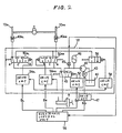
- Fig. 2 there is schematically illustrated an arrangement of an accumulator pressure control apparatus according to an embodiment of the present invention which is incorporated into a braking control system of a motor vehicle.
- the braking control system 18 is arranged so as to operate left and right side braking devices 40RL and 40RR to brake the left and right driven wheels 10RL and 10RR (illustrating only two of the wheels of the motor vehicle) in accordance with control signals So, BL, BR from an electronic control unit 16.
- the electronic control unit 16 comprises a microcomputer including a central processing unit (CPU), a read-only memory (ROM), a random access memory (RAM), an input/output port (I/O) and so on.
- CPU central processing unit
- ROM read-only memory
- RAM random access memory
- I/O input/output port
- the control signals So, BL, BR therefrom are respectively supplied to drive circuits 52, 54RL, 54RR so as to drive a hydraulic-pressure passage change-over valve 48, a left-side hydraulic pressure control valve 50RL and a right-side hydraulic pressure control valve 50RR so that the braking forces applied to the left and right driven wheels 10RL and 10RR by the braking devices 40RL and 40RR are controllable.
- the hydraulic pressure of an accumulator 46 is accumulated by means of a pump 42 driven by a motor 43, the inlet side of the pump 42 being coupled to a reservoir 44.
- the hydraulic-pressure passage change-over valve 48 is a two-position solenoid valve whereby the braking devices 40RL and 40RR are coupled through the hydraulic pressure control valves 50RL and 50RR to the accumulator 46 or a braking master cylinder 9. Normally, the change-over valve 48 takes a position so that the braking master cylinder 9 is coupled to the braking devices 40RL and 40RR, whereby the braking operations of the wheels 10RL and 10RR can be effected by depression of a braking pedal made by the vehicle driver.
- the change-over valve 48 is switched by the drive circuit 52 to take another position whereby the braking devices 40RL and 4ORR are coupled to the accumulator 46 to allow execution of the anti-skid control, for example.
- Each of the left and right side hydraulic pressure control valves 50RL and 50RR is a three-position solenoid valve which controls the braking hydraulic pressure applied to the left or right wheel by taking positions a , b , c through the drive circuit 54RL or 54RR in accordance with the control signal BL or BR from the electronic control unit 16 with the change-over vlave 48 being switched to the accumulator 46 side.
- the drive circuits 54RL and 54RR are started in response to the control signal So from the electronic control unit 16 so as to control the hydraulic pressure control valves 50RL and 50RR in accordance with the control signals BL and BR therefrom, the control of the control valves 50RL and 50RR being effected until the control signal So is stopped.
- the braking hydraulic pressure increasing and decreasing control is performed with each of the control valves 50RL and 50RR taking the positions a , b , c in accordance with the pressure increasing or decreasing duty ratio D corresponding to the control signal BL or BR.
- the electronic control unit 16 outputs the control signal So when one driven wheel 10RL or 10RR becomes in a slipping state at the time of acceleration of the motor vehicle or the like and the slipping amount exceeds a predetermined reference value.
- the braking control amount of each of the right and left wheels 10RL and 10RR is determined in accordance with the difference between the wheel slipping amount and the predetermined reference value.
- the braking control system 18 is provided with a pressure sensor 45 for sensing the hydraulic pressure of the accumulator 46 and generating a signal indicative of the sensed hydraulic pressure thereof.
- the signal therefrom is supplied to the electronic control unit 16 which in turn outputs a drive signal Ms to a motor drive circuit 47 to drive the pump 42 by means of the motor 43 when the hydraulic pressure of the accumulator 46 is fallen down below a predetermined value, whereby the hydraulic pressure of the accumulator 46 is kept to an appropriate value.
- Fig. 3 is a block diagram useful for easily understanding the arrangement of the accumulator pressure control apparatus according to the embodiment of this invention.
- reference Ml represents the accumulator 46
- M4 designates the pressure sensor 45
- M5 depicts a control valve means corresponding to the change-over valve 48 and control valves 50RL, 50RR
- M6 represents a braking means corresponding to the braking devices 40RL, 40RR
- M8 designates a valve drive circuit means corresponding to the drive circuits 52, 54RL, 54RR.
- the electronic control unit 16 is provided in function with a slip control means 16a for calculating the slip amount of the driven wheel and so on and outputting the control signals So, BL, BR to the valve drive circuit means M8, a pressure decision means 16b coupled through an input circuit means 16e to the pressure senor M4 to determine the lowering of the hydraulic pressure of the accumulator M1 in accordance with the signal indicative of the accumulator pressure from the pressure sensor M4 and coupled to a control means 16d which in turn energizes the motor drive circuit 47, and a consumption time calculating means 16c for obtaining, or integrating, the time of consumption of the accumulator M1 pressure due to the opening of the control valve means M5 on the basis of the control signals So, BL, BR.
- the input circuit means 16e is for converting the pressure-indicating signal from the pressure sensor M4 into the corresponding digital signal and the control means 16d is for outputting a drive signal to the motor drive circuit 47 when the obtained consumption time is over a predetermined time.
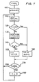
- Fig. 4 is a flow chart showing control executed in the microcomputer of the electronic control unit 16, the control being effected by the CPU in accordance with a program prestored in the ROM.
- the control in response to turning-on of an ignition switch (not shown) of the motor vehicle, the control starts with a step 100 in which the initialization is executed, for example, various counters are cleared.
- the initialization step 100 is followed by a step 110 to input a signal from the pressure sensor 45 indicative of the hydraulic pressure of the accumulator 46 and further followed by a step 120 to check whether the accumulator pressure is below a predetermined value or is in the normal pressure state. If the accumulator pressure is below the predetermined value, a step 160 follows to output a motor drive signal.
- a step 130 follows to indirectly obtain the consumption time of the accumulator pressure on the basis of the control signals So, BL and BR.
- the consumption time T is integrated at every calculation cycle.
- a step 140 is executed in order to check whether the integrated consumption time T is equal to or over a predetermined time T1.
- T ⁇ Tl indirectly indicating that the accumulator pressure becomes in a pressure-lowered state due to the consumption
- control advances to a step 150 to stop the outputting of the motor drive signal.
- a step 180 it is checked on the basis of the presence of the control signals So, BL, BR whether the motor vehicle is on the slip control. If it is not on the slip control, a step 180 follows to clear the integrated consumption time T. If so, the operational flow returns to the step 110.
- the predetermined time T1 may be determined so as to prevent the pump 42 from being driven by accident when the control valves 50RL and 50RR are opened due to a shock of the motor vehicle.
- the predetermined time T1 is determined to be over about 50 msec. Furthermore, the predetermined time T1 is determined to be sufficiently short (for example, below about 150 msec.) as compared with the time at which the accumulator pressure becomes in the pressure-lowered state, thereby resulting in quickly driving the pump 42.
- the pump 42 is operated in response to the signal from the pressure sensor 45.
- the consumption time T is calculated as the sum of the accumulator-pressure consuming times for all the wheels.
- Fig. 5 is an illustration for describing another embodiment of the present invention and shows a three-channel anti-skid control system 70 for controlling the braking hydraulic pressures to be applied to the front-left wheel 10FL, front-right wheel 10FR and the rear wheels (driven wheels) 10RL, 10RR and a slip control system 71 for preventing the slip of the rear wheels 10RL, 10RR on start of the motor vehicle and the like.
- rapid-and-slow control valves 61FL, 61FR, 61R which have the same structure with each other and increasing-and-decreasing control valves 62FL, 62FR, 62R which have the same structure with each other are respectively kept to the deenergized states and, in response to the braking of the motor vehicle by the vehicle driver, the braking hydraulic pressure from a master cylinder 9 is supplied through cut valves 60FL, 60FR, 60R, which have the same structure with each other, to braking devices (not shown) for the respective wheels 10FR, 10FR, 10RL, 10RR.
- the flow of the hydraulic pressure in each of the cut valves 60FL, 60FR, 60R advances through a chamber 60A, a chamber 60B, a chamber 60C and a chamber 60D in sequence.
- an electronic control unit 80 (corresponding to the control unit 16 in the first-mentioned embodiment) has determined that the wheel or wheels 10FL to 10RR are in the locked states due to a rapid braking operation
- the electronic control unit 80 controls the rapid-and-slow control valve or valves 61FL to 61R and the increasing-and-decreasing control valve or valves 62FL to 62R so as to results in a rapid-decreasing mode.
- the rapid-and-slow control valves 61FL to 61R are maintained as it are and only the increasing-and-decreasing control valves 62FL to 62R are energized so as to respectively take positions b (Fig. 5) from positions a taken in the normal states, i.e., deenergized state, whereby the braking pressures in wheel cylinders (illustrated by character W/C in Fig. 5) of the above-mentioned braking devices are rapidly decreased by means of the actions of the cut valves 60FL, 60FR, 60R.
- a decreasing piston 60E is fallen down so that a ball valve 60G cuts off the gamication between the chambers 60A and 60B to rapidly increase the volume of the chamber 60B, resulting in decrease in the wheel cylinder pressure by a value corresponding to the volume increase of the chamber 60B.
- the electronic control unit 80 energizes both the rapid-and-slow control valves 61FL to 61R and the increasing-and-decreasing control valves 62FL to 62R.
- the rapid-and-slow control valves 6lFL to 6lR are respectively switched from normal (deenergized) positions a to positions b ,whereby the volume of the chamber 60B of each of the cut valves 60FL to 60R is slowly increased so as to slowly decrease the braking pressure in the wheel cylinder by a value coresponding to the volume increase of the chamber 60B.
- both the rapid-and-slow control valves 61FL to 61R and the increasing-and-decreasing control valves 62FL to 62R are deenergized to take the positions a .
- the pressure of an accumulator regulated by means of a regulator 69 to be substantially equal to the pressure in the master cylinder 9 is rapidly applied to the decreasing piston 60E of each cut valve (60) which in turn rises so that the volume of the chamber 60B is rapidly decreased to cause the pressure of the wheel cylinder to increase by a value corresponding to the volume decrease.
- the above-mentioned four modes are selectively effected in accordance with the slip ratio of each wheel to prevent the wheel locking and further to assume an appropriate braking distance.
- the reference numeral 68 represents a proportioning valve.
- the electronic control unit 80 energizes a master cylinder cut valve 66, a main control valve 64 and a subcontrol valve 65 each of which in turn takes a position b in Fig. 5.
- the hydraulic pressure in the accumulator 46 is supplied into a cylinder 67 to cause a piston 67a to move to the right direction in Fig. 5 to indirectly increase the braking pressure in the braking devices applied to the driven wheel 10RL or 10RR.
- the main control valve 64 and the subcontrol valve 65 are respectively deenergized so as to take positions a , whereby the braking pressure in the braking devices are indirectly decreased.
- the main control valve 64 is deenergized to take the position a and the subcontrol valve 65 is energized to take the position b , the braking pressure in the braking devices can be kept indirectly to a constant value.
- the electronic control unit 80 integrates the time period of execution of the rapid-decreasing mode in which the increasing-and-decreasing control valve 62 is energized and the rapid-and-slow control valve 61 is deenergized, the time period of the rapid-decreasing mode execution corresponding to the consumption time of the accumulator 46 pressure. If the integrated time period exceeds a predetermined time, the electronic control unit 80 outputs a drive signal to the motor 43 to cause the pressure of the accumulator 46 to increase. Furthermore, on the slip control, the electronic control unit 80 integrates the time period of energizing the master cylinder cut valve 66, main control valve 64 and subcontrol valve 65, as the consumption time of the accumulator pressure.
- the electronic control unit 80 drives the motor 43 to increase the pressure of the accumulator 46.
- the electronic control unit 80 outputs a drive signal to drive the motor 43 to increase the pressure thereof.
- Figs. 6 and 7 are flow chars for describing the processes executed in the electronic control unit 80 on the accumulator pressure control.
- the operational flow starts with a step 200 to perform the initialization, followed by a step 201 to input a pressure signal from the pressure sensor 45 indicative of the accumulator 46 pressure. Thereafter, control goes to a step 202 to check whether the accumulator pressure measured by the pressure sensor 45 is lower than a predetermined value P2. If so, a step 203 follows to set a flag Fsw to "1". If not, a step 204 follows to set the flag Fsw to "0".
- the flag Fsw is for showing the requirement of the motor drive based upon the pressure signal from the pressure sensor 45.
- step 205 the drive signals to the control valves are inputted in order to check the energizing states of the increasing-and-decreasing control valves 62 and rapid-and-slow control valves 61.
- step 206 it is checked whether the motor vehicle is on the anti-skid control or slip control.
- the anti-skid control performing state means that, for example, the wheel speed and wheel acceleration are under predetermined conditions
- the slip control performing state means that the wheel is under a predetermined slip condition.
- the wheel speed may be obtained by means of a wheel speed sensor (not shown) and the wheel acceleration may be calculated on the basis of the obtained wheel speed and further the wheel slip condition may be obtained on the basis of the wheel speed. If the decision of the step 206 is "NO", the steps 208 and 209 are successively executed so as to reset a control timer T A and a consumption timer T B to zero, respectively.
- the control timer T A is used for counting the integrated time after the start of the anti-skid control or slip control and the consumption timer T B is used for counting the integrated consumption time during which the accumulator pressure is under the consumption condition.
- the step 207 follows to increment the control timer T A and then the step 210 follows to check whether the motor vehicle is in the consumption mode.
- the consumption mode means that, in the case of the anti-skid control, the increasing-and-decreasing control valves 62 are in the energized states and the rapid-and-slow control valves 61 are in the deenergized states and, in the case of the slip control, the master cylinder cut valve 66, main control valve 64 and subcontrol valve 65 are respectively in the energized states. If it is in the consumption mode, the step 211 follows to increment the consumption timer T B .
- the control advances to steps 212 and 213 for countermeasures against the air introduction into the accumulator 46. That is, when the pump 42 is driven under the condition that the oil level in the reservoir 44 is lowered, air tends to be introduced into the accumulator 46, and therefore it is required to prevent this air introduction thereinto.
- the electronic control unit 80 inputs a signal from the braking liquid level switch 81 which is provided in the reservoir 44, and in the step 213, it is checked whether the liquid level of the reservoir 44 is lowered below a predetermined value. If so, a step 217 follows so as to set a flag Fsol to zero to inhibit the motor drive. The flag Fsol is used for requiring the motor drive under the condition that the accumulator pressure is consumed.
- a step 214 follows in order to check whether the count value of the control timer T A is zero. If it is zero, since the anti-skid control is not executed, the control goes to the above-mentioned step 217.
- a step 215 is executed to check predetermined conditions ⁇ , that is, (i) whether the integrated consumption time counted by the consumption timer T B is over a predetermined value Ts, i.e., T B ⁇ Ts, (ii) whether the consumption timer T B is started (the accumulator pressure is started to be consumed), i.e., T B is not zero, (iii) whether the integrated elapse time after start of the anti-skid control is over the predetermined value Ts, i.e., T A ⁇ Ts.
- the predetermined value Ts may be set to about 100 ms which is relatively short.
- a step 216 follows to set the flag Fsol to "1". It is also appropriate that, irrespective of the predetermined conditions ⁇ , the step 216 is executed when the anti-skid control is started, that is, when the decision of the step 214 is "NO".
- steps 218 and 219 shown in Fig. 7.
- the steps 218 and 219 are provided to check whether the flag Fsw associated with the pressure switch is "1" and whether the flag sol associated with the accumulator pressure consumption is "1". If either of them is “1”, control is performed for the motor drive. If both are not “1", control is effected for motor stop.
- the step 220 is first executed to check whether the motor 43 is in the stopped state. If not, that is, if the motor 43 is in the driven state, the step 221 follows to check whether the count value Con of an ON-counter is over a predetermined time C1, i.e., Con ⁇ C1.
- the predetermined time C1 represents the minimum time for which the motor 43 is to be continuously driven after the motor drive. If Con ⁇ C1, the step 224 follows to set the ON-counter Con to zero and the step 225 is then executed to increment an OFF-counter Coff by one, followed by a step 226 to step the motor drive.
- step 221 is followed by a step 227 to set the OFF-counter Coff to "0" and then followed by a step 228 to increment the ON-counter Con by one and further followed by a step 229 to continue the motor drive.
- a step 222 is first executed in order to check whether the motor 43 is the ON-state. If not, a step 223 follows to check whether the OFF-counter Coff is over a predetermined time C2.
- the predetermined time C2 is the time for which the motor is to be continuously stopped after the stop of the motor 43. Until Coff becomes greater than C2, the steps 224, 225 and 226 are successively executed so as to stop the motor drive. If Coff ⁇ C2, the steps 227, 228 and 229 are successively executed so as to drive the motor 43.
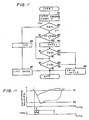
- Fig. 8 is a graphic diagram useful for understanding the effect of the above-mentioned processes described with reference to Figs. 6, 7 flow charts.
- (1) of Fig. 8 shows the variation of the accumulator pressure with respect to the time passage and a solid line represents the case of the above-mentioned embodiment of this invention and a dotted line designates the case of a conventional system effected by only the pressure sensor.
- Fig. 8 shows the variation of the accumulator pressure with respect to the time passage and a solid line represents the case of the above-mentioned embodiment of this invention and a dotted line designates the case of a conventional system effected by only the pressure sensor.
- the reference T6 represents the time at which the anti-skid control or the slip control is started
- T7 designates the time at which the consumption mode where the accumulator pressure is consumed is made
- T8 is the time at which the accumulator pressure reaches the lower limit P2 (the prior system)
- T9 and T11 are the times at which the accumulator pressure exceeds the upper limit P1 (this embodiment and the prior system)
- T10 depicts the time at which the anti-skid control is terminated.
- the control timer T A is started at the anti-skid control start time T6 and then, after the time T7 at which the consumption mode is made, the consumption timer T B successively counts the times T B1 , T B2 , T B3 of the consumption modes.
- the flag Fsol in response to the count value of the consumption timer T B exceeding a predetermined value T BS , the flag Fsol is set to "1" so as to drive the motor 43.
- (ii) and (iii) of (5) show the cases of the above-mentioned other conditions ⁇ , and (iv) represents the case that the flag Fsol is set to "1" under no condition ⁇ , i.e., when the anti-skid control is started, for example.
- the flaf Fsol is set to "0" at the time T10 and the control timer T A is reset to zero thereat so as to stop the motor 43.
- the motor 43 is driven before the time T8 at which the accumulator pressure becomes below the lower limit P2 and stopped before the time T11 at which the accumulator pressure exceeds the upper limit P1, resulting in preventing the occurrance of noises caused by the motor drive.
- a third embodiment of this invention will be described hereinbelow with reference to Figs. 9 and 10.
- the accumulator pressure is compared with the lower limit P2, upper limit P1 and a middle reference value P3 (P1 > P3 > P2). More specifically, as indicated by a solid line of Fig. 10, on the anti-skid control, when the accumulator pressure becomes below the middle reference value P3, the pump 42 is started. On the other hand, if the anti-skid control is not performed, as indicated by a dotted line in Fig. 10, the pump 42 is driven when the accumulator pressure becomes below the lower limit P2.
- FIG. 9 is a flow chart for describing the processes of the third embodiment.
- a step 301 is initially executed to input a pressure signal P indicative of the accumulator pressure from the pressure sensor 45, followed by a step 302 to check whether the accumulator pressure is over the upper limit P1, i.e., P ⁇ P1. If not, a step 303 follows to check whetehr the motor vehicle is on the anti-skid control. If so in the step 303, a step 307 is executed to check whether the pressure signal P is lower than the middle reference value P3, i.e., P ⁇ P3.
- a step 305 follows to output a motor drive signal.
- the operational flow goes to a step 304 to check whether the pressure signal P is lower than the lower limit P2. If P ⁇ P2, control goes to the step 305 to drive the motor 43. Returning back to the step 302, if P ⁇ P1, control goes to a step 306 to stop the motor 43.
- the third embodiment can quicken the completion of the accumulator pressure increase and quickly stop the noises in connection with the termination of the anti-skid control.
- a fourth embodiment of this invention will be described hereinbelow with reference to Figs. 11 and 12.
- One important feature of the fourth embodiment is that, in the normal state, the accumulator pressure is compared with the upper limit P1 and the lower limit P2 and, on the anti-skid control, when the elapse time T after the start of the anti-skid control exceeds a predetermined time Ts, the pump 42 is started.
- the operation of the fourth embodiment starts with a step 401 to input a pressure signal P from the pressure sensor 45, followed by a step 402 in which the pressure signal P is compared with the upper limit P1. If P is lower than Pl, a step 403 follows to check whether the motor vehicle is on the anti-skid control.
- step 403 If the decision of the step 403 is "YES”, the elapse time T measured by a timer is incremented in a step 404 which is in turn followed by a step 405 to check whether the elapse time T is over the predetermined time Ts. If T ⁇ Ts, a step 408 follows to drive the motor 43. On the other hand, in the case of no execution of the anti-skid control or when the decision of the step 405 is "NO", a step 406 is executed to check whether the pressure signal P is compared with the lower limit P2. If P ⁇ P2, control goes to the step 408 to drive the motor 43.
- a step 409 follows to set the timer to zero, followed by a step 407 to stop the motor drive.
- a solid line shows the variation of the accumulator pressure on the anti-skid control and a dotted line represents the variation of the accumulator pressure when the anti-skid control is not performed.
Landscapes
- Engineering & Computer Science (AREA)
- Physics & Mathematics (AREA)
- Fluid Mechanics (AREA)
- Transportation (AREA)
- Mechanical Engineering (AREA)
- Chemical & Material Sciences (AREA)
- Combustion & Propulsion (AREA)
- Regulating Braking Force (AREA)
- Valves And Accessory Devices For Braking Systems (AREA)
Claims (6)
- Drucksammler-Drucksteuereinrichtung für ein Bremssystem eines Motorfahrzeugs, mit:
einer Drucksammlereinrichtung (46; M1) zum Sammeln eines hydraulischen Drucks, der einer Bremseinrichtung (40; M6) zum Bremsen eines Rads (10) des Motorfahrzeugs zugeführt wird;
einer motorbetriebenen Pumpeneinrichtung (42, 43), die mit der Drucksammlereinrichtung (46; M1) zur Erhöhung des hydraulischen Drucks in der Drucksammlereinrichtung (46; M1) gekoppelt ist;
einer zwischen der Drucksammlereinrichtung (46; M1) und der Bremseinrichtung (40; M6) vorgesehenen Steuerventileinrichtung (48, 50, 56; M5; 60, 61, 62, 64, 65, 66, 67) zum Regeln des von der Drucksammlereinrichtung (46; M1) an die Bremseinrichtung anzulegenden hydraulischen Drucks; und
einer Steuereinrichtung (16; 80) zum Steuern der Steuerventileinrichtung (48, 50, 56; M5; 60, 61, 62, 64, 65, 66, 67) für die Regelung des an die Bremseinrichtung angelegten hydraulischen Drucks, und zum Steuern des hydraulischen Drucks in der Drucksammlereinrichtung (46; M1) unter Betätigung der motorbetriebenen Pumpeneinrichtung (42, 43), dadurch gekennzeichnet, daß
die Steuereinrichtung (16; 80) den hydraulischen Druck auf der Grundlage der Steuerungszeit der Steuerventileinrichtung (48, 50, 56; M5; 60, 61, 62, 64, 65, 66, 67) steuert. - Drucksteuereinrichtung nach Anspruch 1, dadurch gekennzeichnet, daß eine Druckfühleinrichtung (45; M4) zum Erfassen des hydraulischen Drucks in der Drucksammlereinrichtung (46; M1) und zum Erzeugen eines den erfaßten hydraulischen Druck anzeigenden Signals vorgesehen ist, und daß die Steuereinrichtung (16; 80) auf das Druckanzeigesignal der Druckfühleinrichtung (45; M4) derart anspricht, daß sie die motorbetriebene Pumpeneinrichtung (42, 43) aktiviert, wenn der hydraulische Druck in der Drucksammlereinrichtung (46; M1) unter einem ersten vorbestimmten Wert liegt, und die motorbetriebene Pumpeneinrichtung (42, 43) abschaltet, wenn der hydraulische Druck in der Drucksammlereinrichtung einen zweiten vorbestimmten Wert erreicht.
- Drucksteuereinrichtung nach Anspruch 1, dadurch gekennzeichnet, daß die Steuereinrichtung (16; 80) die Steuerungszeit der Steuerventileinrichtung ((48, 50, 56; M5; 60, 61, 62, 64, 65, 66, 67) integriert und die motorbetriebene Pumpeneinrichtung (42, 43) aktiviert, wenn die integrierte Steuerungszeit oberhalb einer vorbestimmten Zeitdauer liegt.
- Drucksteuereinrichtung nach Anspruch 1, dadurch gekennzeichnet, daß eine Einrichtung (16; 80) zum Erfassen eines Zustands des Rads (10) vorhanden ist, und daß die Steuereinrichtung (16; 80) die Steuerventileinrichtung (48, 50, 56; M5; 60, 61, 62, 64, 65, 66, 67) in Abhängigkeit von der Erfassung des Radzustands steuert.
- Drucksteuereinrichtung nach Anspruch 4, dadurch gekennzeichnet, daß die Steuerventileinrichtung (48, 50, 56; M5; 60, 61, 62, 64, 65, 66, 67) derart ausgelegt ist, daß sie in Abhängigkeit vom erfaßten Radzustand vorbestimmte Drucksteuer-Betriebsarten für die hydraulische Drucksteuerung einnimmt, und daß die Steuereinrichtung (16; 80) die motorbetriebene Pumpeneinrichtung (42, 43) aktiviert, wenn die Ausführungszeitdauer einer der vorbestimmten Betriebsarten oberhalb einer vorbestimmten Zeitdauer liegt.
- Drucksteuereinrichtung nach Anspruch 2, dadurch gekennzeichnet, daß eine Einrichtung (16; 80) zum Erfassen eines Zustands des Rads (10) und zum Erzeugen eines den Radzustand anzeigenden Signals vorgesehen ist, und daß die Steuereinrichtung (16; 80) auf das Radzustand-Anzeigesignal anspricht, um die motorbetriebene Pumpeneinrichtung (42; 43) zu aktivieren, wenn der erfaßte hydraulische Druck in der Drucksammlereinrichtung (46; M1) unterhalb eines dritten vorbestimmten Werts liegt, der höher als der erste vorbestimmte Wert ist.
Applications Claiming Priority (4)
| Application Number | Priority Date | Filing Date | Title |
|---|---|---|---|
| JP217719/87 | 1987-08-30 | ||
| JP21771987 | 1987-08-30 | ||
| JP63135984A JP2677377B2 (ja) | 1987-08-30 | 1988-06-02 | ブレーキ装置用アキュムレータの圧力制御装置 |
| JP135984/88 | 1988-06-02 |
Publications (2)
| Publication Number | Publication Date |
|---|---|
| EP0305950A1 EP0305950A1 (de) | 1989-03-08 |
| EP0305950B1 true EP0305950B1 (de) | 1992-04-01 |
Family
ID=26469691
Family Applications (1)
| Application Number | Title | Priority Date | Filing Date |
|---|---|---|---|
| EP88114055A Expired - Lifetime EP0305950B1 (de) | 1987-08-30 | 1988-08-29 | Bremssystem mit einem Gerät zum Steuern des in einem Speicher zu sammelnden Drucks zum Bremsen eines Kraftfahrzeugs |
Country Status (4)
| Country | Link |
|---|---|
| US (1) | US4880282A (de) |
| EP (1) | EP0305950B1 (de) |
| JP (1) | JP2677377B2 (de) |
| DE (1) | DE3869702D1 (de) |
Families Citing this family (30)
| Publication number | Priority date | Publication date | Assignee | Title |
|---|---|---|---|---|
| DE3920608A1 (de) * | 1989-06-23 | 1991-01-03 | Audi Ag | Vorrichtung zur verhinderung des einseitigen durchdrehens eines rades an einer antriebsachse mit differentialgetriebe eines kraftfahrzeuges |
| DE4003579C1 (en) * | 1990-02-07 | 1991-06-27 | Mercedes-Benz Aktiengesellschaft, 7000 Stuttgart, De | Anti-lock brake circuit for motor vehicle - has variable volume pressure modulation chamber coupled to brakes by control valves |
| DE4015866C2 (de) * | 1990-05-17 | 2003-06-12 | Continental Teves Ag & Co Ohg | Schaltungsanordnung für eine blockiergeschützte Bremsanlage |
| GB2245038B (en) * | 1990-06-07 | 1994-03-23 | Toyota Motor Co Ltd | Device for detecting accumulator fluid leakage through control valve and restoring proper valve seating |
| JP2885903B2 (ja) * | 1990-08-03 | 1999-04-26 | 本田技研工業株式会社 | 車両用流体圧供給装置 |
| JP2762171B2 (ja) * | 1991-01-09 | 1998-06-04 | 本田技研工業株式会社 | 圧力機器用圧力源 |
| US5373454A (en) * | 1991-01-16 | 1994-12-13 | Honda Giken Kogyo Kabushiki Kaisha | Problem diagnosis system in pressure device control apparatus |
| US5324103A (en) * | 1991-08-20 | 1994-06-28 | Nissan Motor Co., Ltd. | Automotive brake control system |
| DE4135062A1 (de) * | 1991-10-24 | 1993-04-29 | Bosch Gmbh Robert | Verfahren zum beschleunigen des bremseneingriffs im antriebsschlupfregelbetrieb und hydraulische bremsanlage zur durchfuehrung des verfahrens |
| US5253982A (en) * | 1992-11-23 | 1993-10-19 | Vickers, Incorporated | Electrohydraulic pump load control system |
| JP2849972B2 (ja) * | 1993-04-14 | 1999-01-27 | 本田技研工業株式会社 | 流体圧倍力式ブレーキ装置 |
| US5388894A (en) * | 1993-07-08 | 1995-02-14 | Itt Corporation | Pump on demand |
| US5941608A (en) | 1996-03-07 | 1999-08-24 | Kelsey-Hayes Company | Electronic brake management system with manual fail safe |
| EP0891275B1 (de) | 1996-04-25 | 2002-06-26 | Lucas Industries Limited | Elektrohydraulische bremssysteme |
| JPH10148183A (ja) * | 1996-11-20 | 1998-06-02 | Aisin Seiki Co Ltd | 流体圧源装置 |
| US5951260A (en) * | 1997-05-01 | 1999-09-14 | Cummins Engine Company, Inc. | System and method for electronic air compressor control |
| JP3726462B2 (ja) * | 1997-11-21 | 2005-12-14 | アイシン精機株式会社 | 車両の制動制御装置 |
| DE19818174C2 (de) * | 1998-04-23 | 2000-03-02 | Bosch Gmbh Robert | Verfahren und Vorrichtungen zur Ansteuerung einer Pumpe zur Hilfsdruckversorgung einer Fahrzeugbremsanlage |
| DE19828553C1 (de) * | 1998-06-26 | 2000-02-03 | Bosch Gmbh Robert | Verfahren und Vorrichtungen zur Durchführung eines Verfahrens zur Bildung oder Anpassung eines Ansteuersignals zur Ansteuerung eines ein Druckmedium fördernden Mittels eines Fahrzeugbremssystems |
| DE19828552C1 (de) * | 1998-06-26 | 2000-02-03 | Bosch Gmbh Robert | Verfahren und Vorrichtung zur Bildung eines Ansteuersignals zur Ansteuerung einer Pumpe zur Förderung eines Druckmediums in einem Fahrzeugbremssystem |
| GB2344142B (en) | 1998-11-27 | 2003-01-22 | Lucas Ind Plc | Pump motor control in electro-hydraulic braking systems |
| US6170921B1 (en) | 1999-01-21 | 2001-01-09 | Meritor Heavy Vehicle Systems, Llc | Magnetostrictive brake actuation mechanism |
| US6217128B1 (en) | 1999-02-12 | 2001-04-17 | Mico, Inc. | Dual brake valve for a steering assist system |
| US6679564B2 (en) * | 2000-12-22 | 2004-01-20 | Aisin Seiki Kabushiki Kaisha | Auxiliary hydraulic pressure source device for a vehicle |
| US6860569B1 (en) | 2002-05-23 | 2005-03-01 | Kelsey-Hayes Company | Electro-hydraulic brake system with four wheel push through |
| DE102004019511A1 (de) | 2004-04-22 | 2005-11-10 | Zf Friedrichshafen Ag | Verfahren zur Steuerung einer Druckmittelpumpe in einem Kraftfahrzeug |
| JP4507772B2 (ja) * | 2004-09-08 | 2010-07-21 | トヨタ自動車株式会社 | 液圧制御装置 |
| US8370041B2 (en) * | 2008-10-31 | 2013-02-05 | Ford Global Technologies, Llc | Reduced energy vacuum pump control |
| DE102010023865B4 (de) * | 2010-06-15 | 2024-03-28 | Zf Active Safety Gmbh | Hydraulikdruckerzeuger für eine Fahrzeug-Bremsanlage |
| US20150260247A1 (en) * | 2014-03-11 | 2015-09-17 | Caterpillar Inc. | Braking system |
Family Cites Families (14)
| Publication number | Priority date | Publication date | Assignee | Title |
|---|---|---|---|---|
| DE2142552C2 (de) * | 1971-08-25 | 1984-06-07 | Alfred Teves Gmbh, 6000 Frankfurt | Drucksteuerventil für eine Antiblockierregelanlage |
| JPS4833277A (de) * | 1971-08-30 | 1973-05-08 | ||
| DE2701866C2 (de) * | 1976-01-29 | 1986-04-30 | Honda Giken Kogyo K.K., Tokio/Tokyo | Steuereinrichtung für eine blockiergeschützte Fahrzeugbremsanlage |
| DE2822143A1 (de) * | 1978-05-20 | 1979-11-22 | Bosch Gmbh Robert | Antiblockierregelsystem |
| US4428620A (en) * | 1982-03-26 | 1984-01-31 | General Motors Corporation | Vehicle brake control system |
| JPS58133945A (ja) * | 1983-01-19 | 1983-08-09 | Honda Motor Co Ltd | アンチロツクブレ−キ装置の制御装置 |
| ATE65058T1 (de) * | 1983-12-07 | 1991-07-15 | Bosch Gmbh Robert | Ueberwachungseinrichtung in einem mit einem antiblockierregelsystem versehenen fahrzeugbremssystem. |
| DE3347618A1 (de) * | 1983-12-30 | 1985-07-18 | Daimler-Benz Ag, 7000 Stuttgart | Hydraulische zweikreis-bremsanlage fuer strassenfahrzeuge |
| JPS60209354A (ja) * | 1984-04-04 | 1985-10-21 | Aisin Seiki Co Ltd | アンチスキッド制御装置 |
| DE3418042A1 (de) * | 1984-05-15 | 1985-11-21 | Alfred Teves Gmbh, 6000 Frankfurt | Vorrichtung zur ueberwachung des hilfsenergie-druckes einer schlupfgeregelten bremsanlage |
| JPS61244648A (ja) * | 1985-04-24 | 1986-10-30 | Nippon Denso Co Ltd | アンチスキツド制御装置 |
| JPS62137262A (ja) * | 1985-12-09 | 1987-06-20 | Toyota Motor Corp | 電動式負圧ポンプの駆動制御装置 |
| JPH05316466A (ja) * | 1992-05-08 | 1993-11-26 | Olympus Optical Co Ltd | 画像記録再生装置 |
| JP2803496B2 (ja) * | 1992-10-30 | 1998-09-24 | 日産自動車株式会社 | 差動制限トルク制御装置 |
-
1988
- 1988-06-02 JP JP63135984A patent/JP2677377B2/ja not_active Expired - Lifetime
- 1988-08-29 EP EP88114055A patent/EP0305950B1/de not_active Expired - Lifetime
- 1988-08-29 DE DE8888114055T patent/DE3869702D1/de not_active Expired - Lifetime
-
1989
- 1989-04-12 US US07/344,480 patent/US4880282A/en not_active Expired - Lifetime
Non-Patent Citations (3)
| Title |
|---|
| ATZ - AUTOMOBILTECHNISCHE ZEITSCHRIFT volume 89, no. 6, June 1987, Stuttgart; pages 325-328; M. Kahrs * |
| PATENT ABSTRACTS OF JAPAN, volume 10, no. 200(M-498) (2256) 12th July 1986 * |
| PATENT ABSTRACTS OF JAPAN, volume 7, no. 246(M-253) (1391) 2nd November 1983 * |
Also Published As
| Publication number | Publication date |
|---|---|
| JPH01257662A (ja) | 1989-10-13 |
| US4880282A (en) | 1989-11-14 |
| EP0305950A1 (de) | 1989-03-08 |
| DE3869702D1 (de) | 1992-05-07 |
| JP2677377B2 (ja) | 1997-11-17 |
Similar Documents
| Publication | Publication Date | Title |
|---|---|---|
| EP0305950B1 (de) | Bremssystem mit einem Gerät zum Steuern des in einem Speicher zu sammelnden Drucks zum Bremsen eines Kraftfahrzeugs | |
| US5547264A (en) | Braking force distribution control system | |
| US6456920B1 (en) | Apparatus for estimating a vehicle side slip angle | |
| US7020551B2 (en) | Roll stability control system | |
| EP0276818B2 (de) | Blockierschutz-Steuerverfahren für Fahrzeuge | |
| EP1721796B1 (de) | Druckerhöhung für Hinterradbremskreise von Fahrzeugen | |
| EP0658462B1 (de) | Anti-Blockier Regler | |
| EP0325291B1 (de) | Verfahren und Vorrichtung zur Traktionssteuerung für Kraftfahrzeuge | |
| US6089682A (en) | Antilock brake control system for vehicle | |
| US6309032B1 (en) | Brake control apparatus with a stroke simulator | |
| EP0259884B1 (de) | Vorrichtung zur Regelung des Radschlupfs | |
| US4955671A (en) | Antiskid control device | |
| US6012782A (en) | Apparatus for controlling differences in braking torque between left and right wheels of vehicle | |
| US6290311B1 (en) | Brake system of vehicle for simultaneous execution of driver's braking and automatic behavior control | |
| US4769758A (en) | Antiskid control system responsive to road surface reaction | |
| EP0182374B1 (de) | Anfahrhilfe | |
| US5369585A (en) | Anti-lock control system for motor vehicles | |
| US5176430A (en) | Anti-skid control system for an automotive vehicle | |
| JPH0995228A (ja) | 車両の制動力制御装置 | |
| EP0616580B1 (de) | Vereinfachtes abs-system für eine achse | |
| US5116109A (en) | Anti-skid control system for an automotive vehicle | |
| US5364175A (en) | Anti-skid brake system for wheeled vehicle | |
| US5461565A (en) | Anti-skid apparatus for automotive vehicle | |
| US6161906A (en) | Anti-skid control system | |
| US5064253A (en) | Anti-skid controlling apparatus |
Legal Events
| Date | Code | Title | Description |
|---|---|---|---|
| PUAI | Public reference made under article 153(3) epc to a published international application that has entered the european phase |
Free format text: ORIGINAL CODE: 0009012 |
|
| AK | Designated contracting states |
Kind code of ref document: A1 Designated state(s): DE FR GB |
|
| 17P | Request for examination filed |
Effective date: 19890323 |
|
| 17Q | First examination report despatched |
Effective date: 19900913 |
|
| GRAA | (expected) grant |
Free format text: ORIGINAL CODE: 0009210 |
|
| AK | Designated contracting states |
Kind code of ref document: B1 Designated state(s): DE FR GB |
|
| REF | Corresponds to: |
Ref document number: 3869702 Country of ref document: DE Date of ref document: 19920507 |
|
| ET | Fr: translation filed | ||
| REG | Reference to a national code |
Ref country code: GB Ref legal event code: 746 |
|
| PLBE | No opposition filed within time limit |
Free format text: ORIGINAL CODE: 0009261 |
|
| STAA | Information on the status of an ep patent application or granted ep patent |
Free format text: STATUS: NO OPPOSITION FILED WITHIN TIME LIMIT |
|
| 26N | No opposition filed | ||
| REG | Reference to a national code |
Ref country code: FR Ref legal event code: DL |
|
| REG | Reference to a national code |
Ref country code: GB Ref legal event code: IF02 |
|
| PGFP | Annual fee paid to national office [announced via postgrant information from national office to epo] |
Ref country code: FR Payment date: 20040810 Year of fee payment: 17 |
|
| PGFP | Annual fee paid to national office [announced via postgrant information from national office to epo] |
Ref country code: GB Payment date: 20040825 Year of fee payment: 17 |
|
| PGFP | Annual fee paid to national office [announced via postgrant information from national office to epo] |
Ref country code: DE Payment date: 20040902 Year of fee payment: 17 |
|
| PG25 | Lapsed in a contracting state [announced via postgrant information from national office to epo] |
Ref country code: GB Free format text: LAPSE BECAUSE OF NON-PAYMENT OF DUE FEES Effective date: 20050829 |
|
| PG25 | Lapsed in a contracting state [announced via postgrant information from national office to epo] |
Ref country code: DE Free format text: LAPSE BECAUSE OF NON-PAYMENT OF DUE FEES Effective date: 20060301 |
|
| GBPC | Gb: european patent ceased through non-payment of renewal fee |
Effective date: 20050829 |
|
| PG25 | Lapsed in a contracting state [announced via postgrant information from national office to epo] |
Ref country code: FR Free format text: LAPSE BECAUSE OF NON-PAYMENT OF DUE FEES Effective date: 20060428 |
|
| REG | Reference to a national code |
Ref country code: FR Ref legal event code: ST Effective date: 20060428 |