EP0891275B1 - Elektrohydraulische bremssysteme - Google Patents
Elektrohydraulische bremssysteme Download PDFInfo
- Publication number
- EP0891275B1 EP0891275B1 EP97920809A EP97920809A EP0891275B1 EP 0891275 B1 EP0891275 B1 EP 0891275B1 EP 97920809 A EP97920809 A EP 97920809A EP 97920809 A EP97920809 A EP 97920809A EP 0891275 B1 EP0891275 B1 EP 0891275B1
- Authority
- EP
- European Patent Office
- Prior art keywords
- pressure
- braking
- accumulator
- brake
- level
- Prior art date
- Legal status (The legal status is an assumption and is not a legal conclusion. Google has not performed a legal analysis and makes no representation as to the accuracy of the status listed.)
- Expired - Lifetime
Links
Images


Classifications
-
- B—PERFORMING OPERATIONS; TRANSPORTING
- B60—VEHICLES IN GENERAL
- B60T—VEHICLE BRAKE CONTROL SYSTEMS OR PARTS THEREOF; BRAKE CONTROL SYSTEMS OR PARTS THEREOF, IN GENERAL; ARRANGEMENT OF BRAKING ELEMENTS ON VEHICLES IN GENERAL; PORTABLE DEVICES FOR PREVENTING UNWANTED MOVEMENT OF VEHICLES; VEHICLE MODIFICATIONS TO FACILITATE COOLING OF BRAKES
- B60T8/00—Arrangements for adjusting wheel-braking force to meet varying vehicular or ground-surface conditions, e.g. limiting or varying distribution of braking force
- B60T8/32—Arrangements for adjusting wheel-braking force to meet varying vehicular or ground-surface conditions, e.g. limiting or varying distribution of braking force responsive to a speed condition, e.g. acceleration or deceleration
- B60T8/34—Arrangements for adjusting wheel-braking force to meet varying vehicular or ground-surface conditions, e.g. limiting or varying distribution of braking force responsive to a speed condition, e.g. acceleration or deceleration having a fluid pressure regulator responsive to a speed condition
- B60T8/40—Arrangements for adjusting wheel-braking force to meet varying vehicular or ground-surface conditions, e.g. limiting or varying distribution of braking force responsive to a speed condition, e.g. acceleration or deceleration having a fluid pressure regulator responsive to a speed condition comprising an additional fluid circuit including fluid pressurising means for modifying the pressure of the braking fluid, e.g. including wheel driven pumps for detecting a speed condition, or pumps which are controlled by means independent of the braking system
- B60T8/4072—Systems in which a driver input signal is used as a control signal for the additional fluid circuit which is normally used for braking
-
- B—PERFORMING OPERATIONS; TRANSPORTING
- B60—VEHICLES IN GENERAL
- B60T—VEHICLE BRAKE CONTROL SYSTEMS OR PARTS THEREOF; BRAKE CONTROL SYSTEMS OR PARTS THEREOF, IN GENERAL; ARRANGEMENT OF BRAKING ELEMENTS ON VEHICLES IN GENERAL; PORTABLE DEVICES FOR PREVENTING UNWANTED MOVEMENT OF VEHICLES; VEHICLE MODIFICATIONS TO FACILITATE COOLING OF BRAKES
- B60T13/00—Transmitting braking action from initiating means to ultimate brake actuator with power assistance or drive; Brake systems incorporating such transmitting means, e.g. air-pressure brake systems
- B60T13/10—Transmitting braking action from initiating means to ultimate brake actuator with power assistance or drive; Brake systems incorporating such transmitting means, e.g. air-pressure brake systems with fluid assistance, drive, or release
- B60T13/12—Transmitting braking action from initiating means to ultimate brake actuator with power assistance or drive; Brake systems incorporating such transmitting means, e.g. air-pressure brake systems with fluid assistance, drive, or release the fluid being liquid
- B60T13/14—Transmitting braking action from initiating means to ultimate brake actuator with power assistance or drive; Brake systems incorporating such transmitting means, e.g. air-pressure brake systems with fluid assistance, drive, or release the fluid being liquid using accumulators or reservoirs fed by pumps
- B60T13/148—Arrangements for pressure supply
-
- B—PERFORMING OPERATIONS; TRANSPORTING
- B60—VEHICLES IN GENERAL
- B60T—VEHICLE BRAKE CONTROL SYSTEMS OR PARTS THEREOF; BRAKE CONTROL SYSTEMS OR PARTS THEREOF, IN GENERAL; ARRANGEMENT OF BRAKING ELEMENTS ON VEHICLES IN GENERAL; PORTABLE DEVICES FOR PREVENTING UNWANTED MOVEMENT OF VEHICLES; VEHICLE MODIFICATIONS TO FACILITATE COOLING OF BRAKES
- B60T13/00—Transmitting braking action from initiating means to ultimate brake actuator with power assistance or drive; Brake systems incorporating such transmitting means, e.g. air-pressure brake systems
- B60T13/10—Transmitting braking action from initiating means to ultimate brake actuator with power assistance or drive; Brake systems incorporating such transmitting means, e.g. air-pressure brake systems with fluid assistance, drive, or release
- B60T13/66—Electrical control in fluid-pressure brake systems
- B60T13/68—Electrical control in fluid-pressure brake systems by electrically-controlled valves
- B60T13/686—Electrical control in fluid-pressure brake systems by electrically-controlled valves in hydraulic systems or parts thereof
-
- B—PERFORMING OPERATIONS; TRANSPORTING
- B60—VEHICLES IN GENERAL
- B60T—VEHICLE BRAKE CONTROL SYSTEMS OR PARTS THEREOF; BRAKE CONTROL SYSTEMS OR PARTS THEREOF, IN GENERAL; ARRANGEMENT OF BRAKING ELEMENTS ON VEHICLES IN GENERAL; PORTABLE DEVICES FOR PREVENTING UNWANTED MOVEMENT OF VEHICLES; VEHICLE MODIFICATIONS TO FACILITATE COOLING OF BRAKES
- B60T7/00—Brake-action initiating means
- B60T7/02—Brake-action initiating means for personal initiation
- B60T7/04—Brake-action initiating means for personal initiation foot actuated
- B60T7/042—Brake-action initiating means for personal initiation foot actuated by electrical means, e.g. using travel or force sensors
-
- B—PERFORMING OPERATIONS; TRANSPORTING
- B60—VEHICLES IN GENERAL
- B60T—VEHICLE BRAKE CONTROL SYSTEMS OR PARTS THEREOF; BRAKE CONTROL SYSTEMS OR PARTS THEREOF, IN GENERAL; ARRANGEMENT OF BRAKING ELEMENTS ON VEHICLES IN GENERAL; PORTABLE DEVICES FOR PREVENTING UNWANTED MOVEMENT OF VEHICLES; VEHICLE MODIFICATIONS TO FACILITATE COOLING OF BRAKES
- B60T8/00—Arrangements for adjusting wheel-braking force to meet varying vehicular or ground-surface conditions, e.g. limiting or varying distribution of braking force
- B60T8/26—Arrangements for adjusting wheel-braking force to meet varying vehicular or ground-surface conditions, e.g. limiting or varying distribution of braking force characterised by producing differential braking between front and rear wheels
- B60T8/266—Arrangements for adjusting wheel-braking force to meet varying vehicular or ground-surface conditions, e.g. limiting or varying distribution of braking force characterised by producing differential braking between front and rear wheels using valves or actuators with external control means
- B60T8/267—Arrangements for adjusting wheel-braking force to meet varying vehicular or ground-surface conditions, e.g. limiting or varying distribution of braking force characterised by producing differential braking between front and rear wheels using valves or actuators with external control means for hybrid systems with different kind of brakes on different axles
-
- B—PERFORMING OPERATIONS; TRANSPORTING
- B60—VEHICLES IN GENERAL
- B60T—VEHICLE BRAKE CONTROL SYSTEMS OR PARTS THEREOF; BRAKE CONTROL SYSTEMS OR PARTS THEREOF, IN GENERAL; ARRANGEMENT OF BRAKING ELEMENTS ON VEHICLES IN GENERAL; PORTABLE DEVICES FOR PREVENTING UNWANTED MOVEMENT OF VEHICLES; VEHICLE MODIFICATIONS TO FACILITATE COOLING OF BRAKES
- B60T8/00—Arrangements for adjusting wheel-braking force to meet varying vehicular or ground-surface conditions, e.g. limiting or varying distribution of braking force
- B60T8/32—Arrangements for adjusting wheel-braking force to meet varying vehicular or ground-surface conditions, e.g. limiting or varying distribution of braking force responsive to a speed condition, e.g. acceleration or deceleration
- B60T8/321—Arrangements for adjusting wheel-braking force to meet varying vehicular or ground-surface conditions, e.g. limiting or varying distribution of braking force responsive to a speed condition, e.g. acceleration or deceleration deceleration
- B60T8/3255—Systems in which the braking action is dependent on brake pedal data
-
- B—PERFORMING OPERATIONS; TRANSPORTING
- B60—VEHICLES IN GENERAL
- B60T—VEHICLE BRAKE CONTROL SYSTEMS OR PARTS THEREOF; BRAKE CONTROL SYSTEMS OR PARTS THEREOF, IN GENERAL; ARRANGEMENT OF BRAKING ELEMENTS ON VEHICLES IN GENERAL; PORTABLE DEVICES FOR PREVENTING UNWANTED MOVEMENT OF VEHICLES; VEHICLE MODIFICATIONS TO FACILITATE COOLING OF BRAKES
- B60T8/00—Arrangements for adjusting wheel-braking force to meet varying vehicular or ground-surface conditions, e.g. limiting or varying distribution of braking force
- B60T8/32—Arrangements for adjusting wheel-braking force to meet varying vehicular or ground-surface conditions, e.g. limiting or varying distribution of braking force responsive to a speed condition, e.g. acceleration or deceleration
- B60T8/34—Arrangements for adjusting wheel-braking force to meet varying vehicular or ground-surface conditions, e.g. limiting or varying distribution of braking force responsive to a speed condition, e.g. acceleration or deceleration having a fluid pressure regulator responsive to a speed condition
- B60T8/343—Systems characterised by their lay-out
- B60T8/344—Hydraulic systems
- B60T8/348—4 Channel systems
-
- B—PERFORMING OPERATIONS; TRANSPORTING
- B60—VEHICLES IN GENERAL
- B60T—VEHICLE BRAKE CONTROL SYSTEMS OR PARTS THEREOF; BRAKE CONTROL SYSTEMS OR PARTS THEREOF, IN GENERAL; ARRANGEMENT OF BRAKING ELEMENTS ON VEHICLES IN GENERAL; PORTABLE DEVICES FOR PREVENTING UNWANTED MOVEMENT OF VEHICLES; VEHICLE MODIFICATIONS TO FACILITATE COOLING OF BRAKES
- B60T8/00—Arrangements for adjusting wheel-braking force to meet varying vehicular or ground-surface conditions, e.g. limiting or varying distribution of braking force
- B60T8/32—Arrangements for adjusting wheel-braking force to meet varying vehicular or ground-surface conditions, e.g. limiting or varying distribution of braking force responsive to a speed condition, e.g. acceleration or deceleration
- B60T8/34—Arrangements for adjusting wheel-braking force to meet varying vehicular or ground-surface conditions, e.g. limiting or varying distribution of braking force responsive to a speed condition, e.g. acceleration or deceleration having a fluid pressure regulator responsive to a speed condition
- B60T8/40—Arrangements for adjusting wheel-braking force to meet varying vehicular or ground-surface conditions, e.g. limiting or varying distribution of braking force responsive to a speed condition, e.g. acceleration or deceleration having a fluid pressure regulator responsive to a speed condition comprising an additional fluid circuit including fluid pressurising means for modifying the pressure of the braking fluid, e.g. including wheel driven pumps for detecting a speed condition, or pumps which are controlled by means independent of the braking system
- B60T8/404—Control of the pump unit
-
- B—PERFORMING OPERATIONS; TRANSPORTING
- B60—VEHICLES IN GENERAL
- B60T—VEHICLE BRAKE CONTROL SYSTEMS OR PARTS THEREOF; BRAKE CONTROL SYSTEMS OR PARTS THEREOF, IN GENERAL; ARRANGEMENT OF BRAKING ELEMENTS ON VEHICLES IN GENERAL; PORTABLE DEVICES FOR PREVENTING UNWANTED MOVEMENT OF VEHICLES; VEHICLE MODIFICATIONS TO FACILITATE COOLING OF BRAKES
- B60T8/00—Arrangements for adjusting wheel-braking force to meet varying vehicular or ground-surface conditions, e.g. limiting or varying distribution of braking force
- B60T8/32—Arrangements for adjusting wheel-braking force to meet varying vehicular or ground-surface conditions, e.g. limiting or varying distribution of braking force responsive to a speed condition, e.g. acceleration or deceleration
- B60T8/34—Arrangements for adjusting wheel-braking force to meet varying vehicular or ground-surface conditions, e.g. limiting or varying distribution of braking force responsive to a speed condition, e.g. acceleration or deceleration having a fluid pressure regulator responsive to a speed condition
- B60T8/40—Arrangements for adjusting wheel-braking force to meet varying vehicular or ground-surface conditions, e.g. limiting or varying distribution of braking force responsive to a speed condition, e.g. acceleration or deceleration having a fluid pressure regulator responsive to a speed condition comprising an additional fluid circuit including fluid pressurising means for modifying the pressure of the braking fluid, e.g. including wheel driven pumps for detecting a speed condition, or pumps which are controlled by means independent of the braking system
- B60T8/4072—Systems in which a driver input signal is used as a control signal for the additional fluid circuit which is normally used for braking
- B60T8/4081—Systems with stroke simulating devices for driver input
- B60T8/4086—Systems with stroke simulating devices for driver input the stroke simulating device being connected to, or integrated in the driver input device
-
- B—PERFORMING OPERATIONS; TRANSPORTING
- B60—VEHICLES IN GENERAL
- B60T—VEHICLE BRAKE CONTROL SYSTEMS OR PARTS THEREOF; BRAKE CONTROL SYSTEMS OR PARTS THEREOF, IN GENERAL; ARRANGEMENT OF BRAKING ELEMENTS ON VEHICLES IN GENERAL; PORTABLE DEVICES FOR PREVENTING UNWANTED MOVEMENT OF VEHICLES; VEHICLE MODIFICATIONS TO FACILITATE COOLING OF BRAKES
- B60T8/00—Arrangements for adjusting wheel-braking force to meet varying vehicular or ground-surface conditions, e.g. limiting or varying distribution of braking force
- B60T8/32—Arrangements for adjusting wheel-braking force to meet varying vehicular or ground-surface conditions, e.g. limiting or varying distribution of braking force responsive to a speed condition, e.g. acceleration or deceleration
- B60T8/34—Arrangements for adjusting wheel-braking force to meet varying vehicular or ground-surface conditions, e.g. limiting or varying distribution of braking force responsive to a speed condition, e.g. acceleration or deceleration having a fluid pressure regulator responsive to a speed condition
- B60T8/48—Arrangements for adjusting wheel-braking force to meet varying vehicular or ground-surface conditions, e.g. limiting or varying distribution of braking force responsive to a speed condition, e.g. acceleration or deceleration having a fluid pressure regulator responsive to a speed condition connecting the brake actuator to an alternative or additional source of fluid pressure, e.g. traction control systems
- B60T8/4809—Traction control, stability control, using both the wheel brakes and other automatic braking systems
- B60T8/4827—Traction control, stability control, using both the wheel brakes and other automatic braking systems in hydraulic brake systems
Definitions
- the present invention relates to electro-hydraulic braking EHB systems for motor vehicles.
- Electro-hydraulic braking systems for motor vehicles which comprise a brake pedal, a braking device connected to at least one vehicle wheel, which is capable of being brought into communication with an electronically controlled valve arrangement, in order to apply hydraulic fluid under pressure to the braking device, a hydraulic pump, and a hydraulic pressure reservoir fed by said pump for the provision of hydraulic fluid under pressure which can be passed to the braking device via the electronically controlled valve arrangement, in order to apply hydraulic fluid under pressure, in proportion to the driver's braking demand as sensed at the brake pedal, to the braking device in so called 'brake by wire' mode.
- the braking energy required for braking the vehicle is provided in normal use by the electrically-actuated braking system ("brake-by-wire" mode).
- the braking system can also feature an ancillary hydraulic braking system for the immediate actuation of the brakes ("push-through" mode).
- the area of application of an electro-hydraulic braking system of this form encompasses anti-locking brake system control, anti-slip control, electronic brake force distribution, and Car Dynamic Control, or "CDC".
- EBS electronic braking systems
- a direct connection can be established between the brake pedal and the brakes, in a conventional manner, by means of switch over valves and hydraulic lines, which is referred to as "push-through".
- This system requires a switching device by which, under normal operating conditions, the brake pressure which is produced in the electrical system, and, in the event of a defect in or the failure of the electrical system, the brake pressure produced in the hydraulic ancillary system, is transferred to the brakes.
- the control valve arrangement is usually designed as a slide valve, with the result that leakages and lack of fluid tightness are inevitable. Consequently, a drop in the pressure of the hydraulic fluid contained in the hydraulic pressure reservoir cannot be avoided, in particular if the vehicle remains out of operation for extended periods.
- the components associated with the hydraulic pressure reservoir are constantly subjected to sustained high, and cyclically varying pressure levels which prevail in the hydraulic fluid supply system. This can lead to premature material fatigue, leaks, and similar problems.
- an electrohydraulic braking system wherein a main pressure accumulator supplies the pressure for operating the brakes under the majority of operating conditions but whose maximum value is less than the maximum possible braking demand pressure which may be required to be met in use of the associated vehicle.
- a second, supplementary accumulator is arranged to be switched in.
- this system can supply at higher than normal pressures only the volume stored in the supplementary accumulator. Once the latter volume has been consumed, the pump will re-pressurise the brakes at the same time as it is re-pressurising the main and supplementary accumulators, ie. relatively slowly.
- a vehicle having an arrangement for braking the vehicle automatically when a collision with another vehicle running ahead is predicted.
- the system has an oil pump and a single pressure accumulator. Under normal braking, fluid is supplied to the brake lines via a pair of depressurizing solenoid valves.
- the depressurising valves are closed, a pair of pressurizing solenoid valves are opened, and the pump is energized so that a relatively low pressure is supplied to the brake lines from the pump via the open depressurizing valves.
- the repressurizing valves When a collision is predicted and the vehicle is running at a high speed, the repressurizing valves are closed, the pump is energised and the depressurizing valves are repeatedly opened and closed so that a higher pressure is supplied step-wise to the brake lines from the accumulator via the depressurizing valves.
- the maximum pressure that can be supplied is limited to the low pump pressure at low vehicle speeds and to the (higher) accumulator brake pressure at medium or high vehicle speeds.
- a first aim of the present invention is accordingly to develop an electro-hydraulic braking system capable of "push-through” operation which avoids the disadvantages outlined above, and is capable of meeting the high demand for safety.
- a fluid pressure accumulator (pressurised reservoir) is used to store fluid under pressure, charged by use of a fluid pump or compressor driven either by an electric motor or directly from the engine via a belt and pulley arrangement, for supply to a valve system which is adapted to supply the brake or brakes of a vehicle with fluid pressure in accordance with the level of driver's braking demand.
- the pressure at which the fluid is stored within the accumulator is set at a relatively high level, which is set so as to be sufficient to actuate the brakes of the vehicle over the complete braking range of the vehicle.
- a high pressure accumulator and pump system In order to achieve this relatively high pressure storage, a high pressure accumulator and pump system has to be employed with sufficient volume to supply several low pressure demands as well as sufficient pressure and volume to supply the infrequent high pressure brake applications. Frequent motor starts in such systems are disadvantages and to be avoided if possible.
- an electro-hydraulic braking system for motor vehicles which comprises a brake pedal, a braking device which is associated with at least one vehicle wheel and is capable of being brought into communication with an electronically controlled valve arrangement in order to apply hydraulic fluid under pressure to the braking device, a hydraulic pump, and a fluid pressure accumulator fed by the pump for the provision of pressurised hydraulic fluid which can be passed to the braking device via the electronically controlled valve arrangement, in order to apply hydraulic fluid under pressure, in proportion to the driver's braking demand as sensed at the brake pedal, to the braking device in a 'brake by wire' mode, a first means which provides a level of fluid pressure supply within the electro-hydraulic system whose highest value is less than that sufficient for the maximum possible braking demand level which may be required to be met in use of the vehicle, and a second means which, upon recognition of a braking demand level or of a potential braking demand level which exceeds or will exceed that which can be achieved by said highest value of
- an electro-hydraulic braking system for motor vehicles which comprises a brake pedal, braking device which is associated with at least one vehicle wheel and is capable of being brought into communication with an electronically controlled valve arrangement in order to apply hydraulic fluid under pressure to the braking device, a hydraulic pump, and a fluid pressure accumulator fed by the pump, for the provision of pressurised hydraulic fluid which can be passed to the braking device via the electronically valve arrangement, in order to apply hydraulic fluid under pressure, in proportion to the driver's braking demand as sensed at the brake pedal, to the braking device in a 'brake by wire' mode a first means which provides a level of fluid pressure supply within the electro-hydraulic system whose highest value is less than that sufficient for the maximum possible braking demand level which may be required to be met in use of the vehicle, and a second means which, upon recognition of a braking demand level or of a potential braking demand level which exceeds or will exceed that which can be achieved by said highest value of fluid pressure supply available
- the second means can be adapted to charge the accumulator to a higher pressure level, in advance of a high demand condition, in accordance with a detected or predicted level of brake fade, or lining fade change.
- the detected or predicted brake fade is measured over several vehicle stops and said detected level of lining fade is measured over a single stop.
- the increase in stiffness can be achieved by arranging a controllable shut-off valve between the hydraulic pump and the accumulator (hydraulic pressure reservoir) in order to enable a connection between the hydraulic pump and the accumulator to be selectively created or removed.
- control valve arrangements are designed preferably as slide valves, which incur leakages as an inherent result of the design, the presence of the shut-of valve prevents any seepage of the brake fluid stored in the hydraulic pressure reservoir, or a drop in the operating pressure in the hydraulic pressure reservoir itself. This is of particular significance if the vehicle remains out of operation for an extended period.
- the shut-off valve is designed as an electro-magnetically actuatable ball valve. Ball valves are free of leaks as an inherent result of their operational principle, with the result that the concept on which this aspect of the invention is based can be achieved particularly easily.
- the shut-off valve can be a spool (slide) valve. Leakage will be low if a long overlap is used; both operating current and size can be reduced significantly if a spool valve of this type is used.
- an electronic control unit (ECU) is provided, which is connected with a first sensor for the acquisition of the static and dynamic conditions prevailing in the braking system and, in particular, at the brake pedal, and the signals issued from the latter sensor are used for the generation of control signals for the shut-off valve.
- ECU electronice control unit
- the hydraulic pressure reservoir is preferably designed as a gas-pressure reservoir, and the electronic control device is designed in such a way as to actuate the hydraulic pump, as a function of a signal from a second sensor, in order to charge the hydraulic pressure reservoir.
- the ideal operating pressure of the hydraulic pressure reservoir/accumulator is of the order of between 130 bar and 160 bar. If a gas-pressure reservoir is used as the hydraulic pressure reservoir, the gas filling pressure is dependent on the gas temperature and the ambient temperature respectively. This means that if the gas pressure reservoir is preloaded at a temperature of 20°C to a gas filling pressure of 90 bar, and the temperature drops to -40°C, the gas filling pressure will drop to about 16 bar.
- the pressure in the hydraulic pressure reservoir is monitored by a sensor. If the pressure falls to a value below Pmin e.g. 110 bar, the shut-off valve will be opened and the hydraulic pump set in operation, in order to recharge the pressure reservoir. If brake actuation is necessary during the recharging operation, the shut-off valve provides the possibility of the hydraulic pressure reservoir being blocked off, with the result that the filling of the wheel brakes with brake fluid can take place directly by means of the hydraulic pump. In view of the fact that the hydraulic pressure reservoir is blocked of, the pump does not deliver any brake fluid into the hydraulic pressure reservoir during the brake actuation period, with the result that a more rapid pressure build-up can take place in the wheel brakes.
- Pmin e.g. 110 bar
- the electronic control unit can be designed, as a function of a signal initiated by the actuation of the brake pedal from said the first sensor, as well as a signal generated as a result of a hydraulic pressure in the hydraulic pressure reservoir which is below a predetermined value, deriving from the second sensor, to actuate the shut-off valve in the sense of supplanting the connection between the hydraulic pump and the hydraulic pressure reservoir.
- the electronic control unit can be designed to actuate the shut-off valve in the sense of supplanting the connection between the hydraulic pump and the hydraulic pressure reservoir, and to impose actuation signals on the hydraulic pump in such a way that the hydraulic pump generates a predetermined pressure profile, which is acquired by the sensors present in the braking system, and is conducted in the form of corresponding sensor signals to the electronic control unit (ECU), for the purpose of effecting a comparison between the predetermined pressure profile and the pressure curve acquired by the sensors.
- monitoring can be provided for the pressure sensors by means of a specific pressure curve being predetermined for the pump, this curve being compared with the pressure curve acquired by means of the pressure sensors.
- the electronic control unit can be designed so as to acruate the shut-off valve in the sense of establishing the connection between the hydraulic pump and the hydraulic pressure reservoir, and to impose actuation signals on the hydraulic pump, in such a way that the hydraulic pump creates a hydraulic pressure which is above the maximum operating pressure of the hydraulic pressure reservoir.
- a pressure reservoir with smaller volume can also be used, as a result of which installation space can be saved, since the desired pressure curves can be achieved by means of an appropriate hydraulic pump.
- the initially stated problem is solved by arranging for the pump to be started immediately if brake-pressure demand cannot be fulfilled, the accumulator pressure-based cut-in level being set to be less than the maximum brake-pressure requirement.
- the conventional arrangement is to have the cut-in pressure equal to or higher than the maximum braking requirement.
- This has the disadvantages of high motor, accumulator and pump cost if the cut-out pressure is set at normal range above cut-in pressure.
- higher energy consumption is incurred due to the high pressures. If the range is reduced, then the motor starts more often, leading to poor durability, especially of brushgear.
- the initially stated problem is solved by arranging for the pump to charge the accumulator in accordance with the detected or calculated brake condition, such as brake fade over several stops, or lining fade change during a single stop.
- brake temperatures may be so high that future brake applications will need to be at an elevated pressure and accumulator pressure can be increased in advance in anticipation.
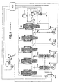
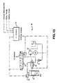
- the braking system shown in Figure 1 includes, for the purpose of the emergency actuation, a "push through" brake circuit 100, which is fed from a brake cylinder 102, actuated by means of the brake pedal 101.
- the brake pedal 101 has an associated sensor 101a for the acquisition of the drivers braking demand.
- the driver's demand is transferred to an electronic control unit (ECU), evaluated there, and used as the source for the generation of electrical control signals for actuating valves, described in greater detail hereinafter, and a hydraulic pump 110.
- ECU electronice control unit
- Switch-over valves 104a, 104b are arranged between the "push-through” brake circuit 100 and the wheel brakes of a vehicle axle 103a, 103b, in order to apply brake fluid to the wheel brakes 103a, 103b, either via the "push-through” brake circuit 100, or via electrically-actuated brake channels 105a, 105b (brake-by-wire).
- the switch over valves 104a, 104b in the electrically non-actuated state, i.e. their preferred position, connect the "push-through" brake circuit 100 with the wheel brakes 103a, 103b, in which situation the connection to the electrically actuated brake channels 105a, 105b is blocked.
- the switch-over valves 104a, 104b connect the wheel brakes 103a, 103b, with the electrically-actuated brake channels 105a, 105b, allocated to them, in which context, the connections to the "push-through” brake circuit 100 are blocked.
- the switch-over valves 104a, 104b are each capable of being moved into the preferred position corresponding to the "push-through" actuation, by means of pressure control lines 106a, 106b.
- de-coupling or separation cylinders 108a, 108b are connected in the electrically-actuated brake channels 105a, 105b, upstream of the switch-over valves 104a, 104b.
- cylinders 108a, 108b hydraulic separation between the "push-through" brake circuit 100 and the electrically-actuated brake channels 105a, 105b is ensured.
- 105d which are allocated to the wheel brakes of the other vehicle axle 103c, 103d, is effected in a known manner by means of control valves 109a, 109b, 109c, 109d, the brake pressure being provided by a pump 110 operated by an electric motor, and from a pressure reservoir 111 consisting of a modular unit.
- shut-off valves 112 and 113 are arranged between the electrically-actuated brake channels of a vehicle axle 105a, 105b and 105c, 105d respectively. These shut-off valves 112 and 113, in the non-actuated state, respectively connect the brake channels 105a, 105b and 105c, 105d to one another, while the brake channels 105a, 105b and 105c, 105d are mutually blocked in the actuated state. As a result of this, the possibility arises of the brake channels of a vehicle axle 105a, 105b and 105c, 105d being hydraulically connected.
- the system as described thus far is conventional and operates in accordance with well-known techniques.
- the system of Figure 1 differs from conventional systems in that a shut-off valve 120 is arranged between the hydraulic pump 110 and the hydraulic pressure reservoir 111, and is designed as a ball valve.
- this shut-off valve 120 By means of this shut-off valve 120, it is possible for leakage problems at the slide valves 109a-109d to be circumvented.
- the motor pump unit can be used for pressure modulation (instead of the pressure reservoir 111 or in support of this).
- the hydraulic pressure chamber 111 can be isolated from the remainder of the brake system by the shut-off valve 120. This accordingly stiffens the system and makes a more dynamic pressure build-up possible.
- the pressure in the pressure reservoir 111 is monitored by a sensor 122. If the pressure falls to a value below, for example 110 bar, then the shut-off valve 120 is opened and the pump 110 goes into operation, in order to recharge the pressure reservoir. In the event of brake actuation being necessary during the recharging process, the shut-off valve 120 provides the possibility of the pressure reservoir 111 being blocked off, with the result that the wheel brakes 103a, 103b, 103c, 103d can be pressurised directly by the pump 110.
- the pump does not deliver any brake fluid into the pressure reservoir 111 during brake actuation, with the result that a more rapid pressure build-up can take place in the wheel brakes 103a, 103b, 103c, 103d.
- the present system of Fig. 1 also enables higher pressures required to accommodate brake fade conditions to be met using an accumulator with a lower maximum working pressure.
- the maximum pressures demanded by the system lie below 120 bar so that an accumulator charged to 120 bar can satisfactorily meet virtually all demand pressures.
- the accumulator is run continuously at 200 bar+ to accommodate these conditions, then accumulator life is short due, inter alia, to increased gas diffusion.
- the accumulator volume in the system results in an unacceptably slow pressure rise rate.
- the accumulator 111 can be operated at a relatively low pressure, eg 120 bar and, if then higher pressures are required at the brakes, the pump output flow can be diverted by the shut-off valve 120 into the brakes without going into the accumulator at all.
- the pressure can be controlled by switching off the pump (and on again if necessary) or by leaving the pump running continuously and controlling its delivery pressure by using a valve to spill excess fluid to the storage tank.
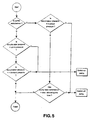
- FIG. 2 is a flow diagram showing one possible arrangement for controlling the pump 110 and shut-off valve 120 (accumulator isolation) in accordance with the detection of "fade" conditions.
- the entry point for the accumulator pressure control algorithm starts at (1). For normal, low braking demands where not previous supercharging or fade detection has occurred, a flag is tested at (2) to determine whether the cut-in and cut-out thresholds should be reset. For normal braking, the cut-in and cut-out threshold are set to a 'normal' low pressure level (3). A test is now made to check if the pump is currently running (4). Normally, where there is sufficient pressure stored within the accumulator to supply the brake demand, the pump would not be running at this point but this would be monitored by checking the actual brake pressure against the level of pressure stored within the accumulator (6).
- the pump would be allowed to run for at least a prescribed maximum period (18) designed so as to prevent the motor from overrunning in a fault condition. This period is monitored (19) and should it be exceeded the pump would be switched off (16). This cycle would continue until the cut-out threshold was reached.
- Supercharging by definition is the direct use of the pump to supply the brake control system with sufficient fluid pressure supply having first reduced the level of compliance within the fluid pressure supply system by preferably isolating the fluid pressure accumulator.
- This control method is used when the demand pressure level is greater than the stored accumulator pressure (5).
- the pump is energized (20) and whilst the brake pressure demand is higher than the accumulator pressure (21) and the vehicle is moving (22) the supercharging process starts.
- the isolation valve can then be re-opened when either the brake pressure drops below the stored accumulator pressure (21) or the vehicle stops moving (22). If the isolation valve is closed, i.e. the accumulator is isolated (7), the pressure control mode is then re-set to normal operation (30) and the isolation valve is then opened (31) to re-connect the accumulator to the brake system (10),
- FIG. 1 The same basic system shown in Fig. 1 is used but without the shut-off valve 120 and its associated control logic.
- a simplified version of the hydraulic circuit of a conventional system is shown in Fig. 3, but giving more details of the control valves. Equivalent parts in Figures 1 and 3 are given the same reference numbers.
- the system of Fig. 3 includes an accumulator 111 for the storage of hydraulic fluid under pressure. As brake demands are serviced, fluid is drawn from the accumulator, and its pressure falls.
- the accumulator is provided with a charging system comprising an electrically-driven pump 110. sensing and control means to start and stop the pump motor, a relief valve 130 and a reservoir 132 from which charging fluid is supplied and to which fluid is returned from the braking circuits at the completion of each brake application.
- This group of components comprise the system's power source.
- the sensing and control means conventionally include an accumulator-pressure sensor, but the elimination of this would be an attractive cost-reduction measure.
- the accumulator 111 provides an instantly-available source of pressurised fluid, enabling rapid application of the vehicle's brakes without the need for a correspondingly large motor and pump. Because motor deterioration is related to the number of times it is started, the fluid volume stored in the accumulator 111 between the cut-out and cut-in pressures is normally arranged to be sufficient for several normal (i.e. low-deceleration) brake applications.
- the objective of the charging system in this arrangement is to maintain the accumulator pressure (and therefore available fluid volume) within a given range, by switching the motor M on when the pressure has decayed to the lower limit of the range, and switching it off when the upper range limit has been re-established.
- switching is controlled by pressure-actuated devices, and so the lower range-limit, henceforth called the cut-in pressure, must be set at or above the maximum pressure required by the system's function. It cannot be set any lower because it would then be possible to achieve a stable situation in which the system failed to fulfill the highest demand pressures.
- 180 bar would be a typical maximum requirement, with normal pressures varying between, say, 10 bar (gentle braking) and 110 bar (laden, high decel.)
- cut-out pressure The upper range-limit, henceforth called the cut-out pressure, is normally determined by any legal obligations and the economics of component design. One of these factors is the durability of the motor and its switching components. A wide range between cut-in and cut-out pressures minimises the number of times the motor must start from rest; but higher cut-out pressures cause increased size, weight and cost of the pump, accumulator and motor. Energy consumption is also increased by pumping to higher pressures. Prior-art cut-out and cut-in pressures are shown on the attached Figs. 4 and 5, for which detailed descriptions are given hereinafter.
- prior-art arrangements ensure that the power source will always be able to fulfill the system's pressure requirements because the pump will cut-in as soon as the accumulator pressure falls below the highest legitimate demand level.
- they are also relatively expensive and wasteful of energy because maximum system pressures are needed only rarely, e.g. arduous fade conditions, but the accumulator is repeatedly charged to a level in excess of this extreme value. It is also known that high operating pressures reduce the life of gas-charged accumulators.
- the alternative system proposed in accordance with the present invention is adapted to start the pump 110 if it is detected that the braking demand cannot be fulfilled. This enables cost and energy savings by reducing cut-in pressure to a level less than the maximum required brake pressure whilst still ensuring that the specified pressure levels can be met.
- the pump 110 is started whenever the accumulator pressure is less than either the cut-in pressure or the highest wheel-demand-pressure signal (derived e.g. from the pedal/master cylinder sensors or from an ABS, CDC. TC algorithm).
- the cut-in pressure or the highest wheel-demand-pressure signal derived e.g. from the pedal/master cylinder sensors or from an ABS, CDC. TC algorithm.
- the pump 110 is started whenever the accumulator pressure is less than the cut-out pressure, i.e. as above, or whenever brake pressure (derived from the brake pressure sensor(s)) is constant and has remained less than the demand signal for that wheel for more than a predetermined time period.
- brake pressure derived from the brake pressure sensor(s)
- the pump 110 will run until the cut-out pressure is reached, or until a predetermined run-time has been exceeded.
- the cut-out pressure may also be reduced, but must still be set at or above the maximum required brake pressure.
- the present arrangement enables a new and more attractive compromise between cost, bulk, energy-consumption and life on one side versus response-time-under-extreme-conditions on the other.
- Prior-art systems being unable to compare demand either with resources or with results, are unable to operate in this optimised fashion.
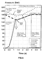
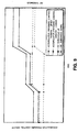
- a graph of pressure against time which illustrates the operation of a demand-signal-based version, contrasted with a prior-art system.
- Prior-art cut-out and cut-in pressures are marked at 220 bar and 180 bar respectively.
- Typical plots of brake-pressure, accumulator pressure and driver's demand are shown for both the prior-art and the new arrangements. In each case a sustained application to the maximum required brake-pressure of 180 bar is assumed. It will be noted that the brake pressure lags fractionally behind the demand signal, although the extent has been exaggerated for clarity.
- the accumulator pressure of the prior-art system is shown having an initial pressure in the middle of its range, with the pump switched off. This is in order to illustrate that the progressive pressurisation of the brakes can cause the accumulator pressure to fall below the cut-in value, and that the pump is too small to prevent the resulting delay in achieving the required pressure of 180 bar. A higher initial pressure may enable settlement to take place above the cut-in pressure, but any initial value between cut-out and cut-in could apply in practice.
- the pump is switched-off (not marked) when the cut-out pressure of 220 bar is reached in the accumulator. It will be noted that, provided the driver is pressing hard enough, the brakes will be pumped-up to the cut-out pressure together with the accumulator, representing further unnecessary energy consumption. The pump started as soon as the accumulator pressure fell below the cut-in pressure of 180 bar.
- the accumulator pressure of the BBW (brake-by-wire) system is shown starting from a fully-charged state, i.e. at a pressure of 180 bar. This is in order to illustrate that the pump can start before the cut-in pressure is reached.
- the settlement pressure is lower than in the prior-art case because of the lower initial pressure (similar accumulator characteristics assumed) and so it takes longer to reach the 180 bar target (similar pumps assumed).
- the initial accumulator pressure could be anywhere between 140 and 180 bar. A low initial value would cause the pump to start on the basis of the accumulator pressure falling below the cut-in value. However, as shown, the pump starts when the demand signal exceeds the accumulator pressure.
- the demand signal may be a signal representing the driver's effort exerted on the pedal.
- it could be the result of a direct measurement of effort, or of pressure in a master-cylinder actuated by the pedal, or of the change-in-length of a spring actuated by the pedal (i.e. of pedal travel).
- the demand signal might be generated in response to automatic braking requirements, such as AICC, CDC, TC etc.
- the pump is switched-off when the accumulator pressure reaches the cut-out pressure, which in this case is the same as the target pressure. However, had the cut-out value been set above the target pressure, only the accumulator would have been pumped-up to the cut-out level. The brakes would then have been pressure-limited by the BBW control valves at the target level.
- Fig. 6 gives more detail of the operation of a response-based version.
- This embodiment does not rely upon the availability of a signal representing accumulator pressure, provided that accumulator pressure can be controlled by other means. It still assumes a knowledge of driver demand, and also needs brake pressure, preferably in the form of a direct measurement from sensors as in Fig. 3, but possibly inferred from other parameters e.g. wheel slip, solenoid energisation history etc.
- brake pressure preferably in the form of a direct measurement from sensors as in Fig. 3, but possibly inferred from other parameters e.g. wheel slip, solenoid energisation history etc.
- the prior art curves are the same as those shown in Fig. 4.
- the BBW cut-out and cut-in characteristics are also the same as those in Fig. 4, but in this case the pump starts because a time "t" has elapsed during which the brake pressure has not risen any further and is still below the target level.
- the delay before fulfilling the target pressure is a little longer than for the Fig. 4 version, by an amount corresponding to the demand-signal lead-time plus "t", but the cost advantage is attractive at prevailing pressure-transducer prices.
- the aforegoing system therefore provides the advantages of enabling the achievement of the maximum brake pressure specification at reduced cost without restricting the pressure difference between pump cut-out and cut-in.
- a further alternative system is now described based on charging the accumulator in accordance with the detected or calculated brake condition, such as brake fade, over several stops or lining mu change during a single stop.
- This system therefore monitors brake usage. When, for example, usage has been sufficiently high in a short time it can be inferred that brake temperatures may be so high that future brake applications will be at elevated pressures. The accumulator pressure can then be increased in anticipation of such applications.
- Brake-by-wire systems are well equipped with sensing elements, including individual wheel brake pressures and individual wheel speeds.
- This data allows a good assessment of brake friction to be made from wheel deceleration divided by brake pressure, being proportional to brake torque divided by brake normal force.
- a useful index can be provided in this connection by using the inverse of the latter function, i.e. brake pressure divided by deceleration, with engineering units of "bar per g", and referred to here as the Brake Pressure Index for Fade, or Brake PIF.
- Typical values might be 100 bar/g for normal braking, going up to 160 or even 220 bar/g for extreme fade.
- the units can thus be thought of as the brake pressure required to achieve a 1g ( ⁇ 10 m.s -2 ) deceleration, with high values being "bad” and low values "good”.
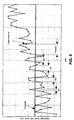
- this index is monitored continuously, its rise over a predetermined threshold is monitored, action then being taken to raise the pressure control window for the accumulator.
- the calculated index should preferably be filtered, for example as shown in Figure 8.
- a time window value is established (Twindow) to ensure that brief excursions over the threshold do not trigger the action.
- Twindow A time window value is established (Twindow) to ensure that brief excursions over the threshold do not trigger the action.
- the first four measurements in Figure 8 have excursions over the threshold of durations dt1 to dt4 respectively, all less than Twindow. The action is not therefore triggered. The fifth excursion lasts much longer, and the action is therefore triggered at the time Twindow after the last crossing over the threshold.
- braking at very low pressures can sometimes give rise to large values of the PIF, due partly to numerical errors in dividing small numbers, and due to the physical behaviour of the friction materials. It is therefore sometimes necessary to inhibit the triggering action at low pressures, i.e. below some predetermined pressure threshold.
- the brake pressure used in calculating the PIF for the vehicle can be a weighted average from all four wheels.
- the deceleration used will normally be that from the vehicle accelerometer, or from wheel speeds with the necessary corrections for gradient. It is also possible to calculate a PIF for each wheel, and take a weighted average of all four for the vehicle, or take a weighted average of pressures and calculate the PIF for the vehicle.
- the wheel brake pressures can vary over a wide range whilst vehicle deceleration may not vary so much. In this case, a more consistent measure of the relevant brake pressure is the peak pressures during each ABS cycle. In most cases it will be somewhat higher than the steady brake pressure required to achieve the same deceleration, and will therefore err somewhat on the cautious side for assessing fade.
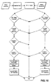
- Fig. 10 is a flow diagram illustrating one possible decision process for accomplishing the further aspect of this invention wherein the accumulator is charged in accordance with a detected or calculated brake condition, such as brake fade.
- a detected or calculated brake condition such as brake fade.
- a similar process can be used to decide when to return to lower or normal pressures.
- the supply pressures may be increased and decreased in more than one step.
- the control of the pressure in the accumulator in prior an systems has been maintained at the maximum pressure needed to meet all braking conditions, P max .
- the maximum pressure has been calculated for the maximum hill. the minimum available frictional coefficient for the brake linings, and maximum vehicle loading.
- Maximum pressure in the accumulator will typically be in the range of 100 bar to 150 bar. Under normal driving conditions, the maximum pressure in the accumulator is in excess of what is needed to safely operate the vehicle. Having the maximum pressure present in the accumulator presents that pressure to the inlet of the proportional control valve(s) 109a, 109b every time the brakes are applied. Such high pressures applied to the inlet of the proportional control valve(s) 54 makes control of the pressure applied to the brakes more difficult than if the pressure were lower.
- a lower pressure presented to the inlet of the proportional control valve(s) would allow the proportional control valve(s) greater time to position themselves, and would effectively raise the accuracy of the control. Furthermore, charging the accumulator to the maximum pressure and volume at all times puts more strain on the pumping components, and contributes to system noise levels.
- the pressure in the accumulator is maintained at the minimum necessary to safely operate the vehicle according to an algorithm computed by the controlling ECU.
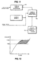
- the ECU receives as inputs to the algorithm, shown schematically in Fig. 13 as f(model), the following parameters:
- FIG. 11 A flow chart of the basic algorithm is shown in Fig. 11.
- step 700 the vehicle deceleration is computed using stored and current values of vehicle speed.
- step 701 the coefficient of friction of the brake linings, ⁇ , is computed using a predetermined program or stored parameter matrix, together with information about the last brake operating cycles, including the brake force used and the resultant vehicle deceleration.
- the computed coefficient of friction ⁇ and the desired vehicle deceleration are then used, in step 702, to compute the necessary braking force to be applied to the brake calipers of the vehicle brakes.
- the amount of pressure and volume of brake fluid necessary to have in the accumulator 46 (see Fig. 13) to effect the required braking force under conditions of high road surface friction is computed, and a signal sent to the accumulator valve 48.
- the accumulator 46 is then pressurized to the required pressure and volume in step 703.
- the ECU 34 of Fig. 13 can be programmed to retrieve and store the vehicle operating parameters over a number of brake operating cycles, or over a predetermined period of time, or both. For example, if the vehicle is operated on a road without use of the brake system for an extended period of time, collecting data based on elapsed time might lead to erroneously low pressure in the accumulator 46. It would therefore be more advantageous in this case to store the data from the last braking applications to determine the correct pressure in the accumulator 46. As a further example, if the vehicle were being operated on a steep downhill with continuous application of the brake system, determining the accumulator 46 pressure base upon a predetermined number of past operating cycles may also lead to an erroneously low pressure in the accumulator 46. In this case, it would be better to base the necessary pressure in the accumulator 46 upon current vehicle operating parameters.
- the controlling ECU 34 is suitably programmed to recognize and adapt the program to the current road and vehicle conditions.
- accumulator 46 has been kept charged to the maximum pressure P max and volume.
- accumulator 46 pressure will be normally kept at a pressure P 90% that will achieve 90% of the design maximum braking effort.
- the f(model) algorithm will be used to determine if the pressure in the accumulator 46 will need to be increased. Only in situations where the extra braking effort is needed such as in the above example, will the accumulator 46 be charged to its maximum pressure.
- Fig. 12 is a graph representative of the pressure and volume curves for accumulator 46, for P max and P 90% . The shaded area between the curves is proportional to the work effort saved by using the reduced pressure and volume in situations where full braking force is unlikely to be needed.
- the advantages of using the reduced pressure in the accumulator 46 are: reduction of noise increased component life cycle; increased control of the proportional control valves and improved control pressure profile characteristics.
- the accumulator 46 will be pressurized to a low pressure or range of pressures.
- the frictional coefficient of the road surface can be estimated by an onboard ECU monitoring vehicle operating parameter based on recent braking cycles. Using a low pressure in the accumulator 46 during times of low friction between the road and the tires allows the brake system to more finely control the amount of pressure applied to the vehicle brakes and better avoid lockup conditions.
- the accumulator 46 should normally be charged to the pressure required to ensure wheel lock on a high friction surface. This pressure can be calculated based on brake layout data, an estimate of the brake pad frictional value (calculated from comparisons of brake pressure and resultant vehicle deceleration during driving) and a temperature model of the brakes to allow for fading problems, etc. However, to ensure a minimum level of braking, a predetermined minimum pressure should be kept in the accumulator 46.
- the charge pressure in the accumulator 46 can be continuously adapted to fit the changing drive and vehicle conditions, and can be measured using either a pressure sensor or digital switches.
- the accumulator 46 can be constructed and operated to have a pressure-volume curve such that most volume of fluid in the accumulator will be stored around the normal maximum brake operating pressure for wheel lock up, not the maximum pressure for wheel lock up under worst case conditions. If P max were required, based on an estimation that the worst case conditions exists, a small additional amount of pressurized fluid would be pumped into the accumulator 46, raising the pressure to P max .
- the accumulator 111 can be arranged to be charged in dependence upon the vehicle speed so that as the vehicle goes faster, the level of stored pressure in the accumulator 111 is also increased, between appropriate cut-in and cut-out limits.
- the philosophy behind this embodiment is that as the driver increases the vehicle speed, from say 48 km/h to 112 km/h (30mph to 70mp) or motorway cruising speed, the more likely he is to demand a high deceleration braking response, and therefore the pressure stored within the accumulator should be appropriately raised in proportion to the vehicle speed as sensed by the vehicle's wheel speed sensors. A simple illustration of this is shown in the attached Figure 14.
- the system according to this embodiment can measure the vehicle speed through use of the vehicle wheel speed sensor.
- This information is used by a system map or look-up table which determines the appropriate cut-in and cut-out pressures for a given vehicle speed.
- This map starts with a substantially low initial threshold setting for a zero speed or vehicle at standstill up to a maximum, relatively high level as the vehicle speed reaches a maximum.
- the pressure level can be limited at a given pressure or speed should that pressure be sufficient to cope with the predicted maximum braking demand.
Claims (9)
- Elektrohydraulisches Bremssystem für Kraftfahrzeuge, das ein Bremspedal (101), eine Bremseinrichtung (103), die mit wenigstens einem Fahrzeugrad verknüpft ist und in Kommunikation mit einer elektronisch gesteuerten Ventilanordnung (109) gebracht werden kann, um Hydraulikfluid unter Druck an die Bremseinrichtung anzulegen, eine Hydraulikpumpe (110) und einen durch die Pumpe (110) gespeisten Flüssigkeitsdruckspeicher (111) zum Liefern von unter Druck stehendem Hydraulikfluid, das über die elektronisch gesteuerte Ventilanordnung (109) zu der Bremseinrichtung (103) geleitet werden kann, um Hydraulikfluid unter Druck im Verhältnis zu der Bremsanforderungen des Fahrers wie am Bremspedal (101) erfasst an die Bremseinrichtung (103) in einer Betriebsart "Bremsen über Elektrokabel" [Brake by Wire-Technik] anzulegen, ein erstes Mittel, das ein Niveau von Flüssigkeitsdruckzufuhr innerhalb des elektrohydraulischen Systems liefert, dessen höchster Wert niedriger als der ist, welcher für das maximal mögliche Bremsanforderungsniveau ausreicht, das bei Gebrauch des Fahrzeugs möglicherweise erreicht werden muss, und ein zweites Mittel umfasst, das bei Erkennen eines Bremsanforderungsniveaus oder eines potentiellen Bremsanforderungsniveaus, das den Wert überschreitet oder überschreiten wird, der erreicht werden kann durch den über das genannte erste Mittel verfügbaren genannten höchsten Wert von Flüssigkeitsdruckzufuhr, ein höheres Niveau von Flüssigkeitsdruckzufuhr innerhalb des Systems zum Steuern der Bremsen in Übereinstimmung mit dem vom Fahrer angeforderten Bremsniveau erzeugt, dadurch gekennzeichnet, dass das genannte zweite Mittel eine Steueranordnung aufweist, die eine Erhöhung der Systemsteifheit bei Erkennen der höheren Bremsanforderung oder der potentiell höheren Anforderung verursacht, die den Wert übersteigt oder übersteigen wird, der durch den über das genannte erste Mittel verfügbaren genannten höchsten Wert der Flüssigkeitsdruckzufuhr erreicht werden kann, durch Isolieren des Flüssigkeitsdruckspeichers (111) von dem Bremssystem, wodurch das Bremssystem dann wirksam direkt von einer motorbetriebenen Pumpe (110) auf ein höheres Flüssigkeitsdruckzufuhrniveau geladen wird, das wenigstens dem vom Fahrer angeforderten Druck entspricht.
- System nach Anspruch 1, bei dem die genannte Steueranordnung eine Ventileinrichtung (120) angeordnet zwischen der Pumpe (110) und dem Flüssigkeitsdruckspeicher (111) aufweist.
- System nach Anspruch 1 oder 2, bei dem der Druck in dem Flüssigkeitsdruckspeicher (111) durch einen Drucksensor (122) kontrolliert wird.
- Elektrohydraulisches Bremssystem für Kraftfahrzeuge, das ein Bremspedal (101), eine Bremseinrichtung (103), die mit wenigstens einem Fahrzeugrad verknüpft ist und in Kommunikation mit einer elektronisch gesteuerten Ventilanordnung (109) gebracht werden kann, um Hydraulikfluid unter Druck an die Bremseinrichtung anzulegen, eine Hydraulikpumpe (110), und einen durch die Pumpe (110) gespeisten Flüssigkeitsdruckspeicher (111) zum Liefern von unter Druck stehendem Hydraulikfluid, das über die elektronische Ventilanordnung (109) zu der Bremseinrichtung (103) geleitet werden kann, um Hydraulikfluid unter Druck im Verhältnis zu der Bremsanforderung des Fahrers wie erfasst am Bremspedal (101) an die Bremseinrichtung (103) in einer Betriebsart "Bremsen über Elektrokabel" [Brake by Wire-Technik] anzulegen, ein erstes Mittel, das ein Niveau von Flüssigkeitsdruckzufuhr innerhalb des elektrohydraulischen Systems liefert, dessen höchster Wert niedriger als der ist, welcher für das maximal mögliche Bremsanforderungsniveau ausreicht, das im Gebrauch des Fahrzeugs möglicherweise erreicht werden muss, und ein zweites Mittel umfasst, das bei Erkennen eines Bremsanforderungsniveaus oder eines potentiellen Bremsanforderungsniveaus, welches den Wert übersteigt oder übersteigen wird, der erreicht werden kann durch den über das genannte erste Mittel verfügbaren genannten höchsten Wert von Flüssigkeitsdruckzufuhr, ein höheres Niveau von Flüssigkeitsdruckzufuhr innerhalb des Systems zum Steuern der Bremsen in Übereinstimmung mit dem vom Fahrer angeforderten Bremsniveau erzeugt, dadurch gekennzeichnet, dass das genannte zweite Mittel ausgelegt ist, um die Pumpe (110) zum Aufladen des Druckspeichers (111) auf ein höheres Niveau anzulassen, entweder wenn das angeforderte Druckniveau auf ein Niveau ansteigt, das höher als das ist, das momentan von dem Druckspeicher erhältlich ist, oder vor einer Hochanforderungsbedingung in Übereinstimmung mit einer ermittelten oder vorhergesagten Bremsbedingung.
- System nach Anspruch 4, bei dem das genannte zweite Mittel ausgelegt ist, um den Druckspeicher (111) auf ein höheres Druckniveau vor einer Hochanforderungsbedingung in Übereinstimmung mit einem ermittelten oder vorhergesagten Niveau von Bremsabnutzung oder Bremsbelagabnutzungsänderung aufzuladen.
- System nach Anspruch 4, bei dem die genannte ermittelte oder vorhergesagte Bremsabnutzung über mehrere Fahrzeugstops gemessen wird und der genannte Grad von Bremsbelagabnutzung über einen einzelnen Schritt gemessen wird.
- System nach Anspruch 4, bei dem das genannte zweite Mittel zum Aufladen des Druckspeichers (111) auf ein höheres Druckniveau vor einer Hochanforderungsbedingung abhängig von der ermittelten Fahrzeuggeschwindigkeit ausgelegt ist.
- System nach Anspruch 7, bei dem, wenn das Fahrzeug schneller fährt, das Niveau von in dem Druckspeicher (111) gespeichertem Flüssigkeitsdruck durch das genannte zweite Mittel zwischen geeigneten Einsatz- und Unterbrechungsgrenzen erhöht wird.
- System nach Anspruch 8, bei dem die Fahrzeuggeschwindigkeit unter Verwendung von Fahrzeugradgeschwindigkeitssensoren gemessen wird, wobei die Information durch einen Systemplan oder eine Nachschlagtabelle verwendet wird, um die geeigneten Einsatz- und Unterbrechungsdrucke für eine gegebene Fahrzeuggeschwindigkeit zu bestimmen.
Applications Claiming Priority (5)
| Application Number | Priority Date | Filing Date | Title |
|---|---|---|---|
| DE19616538 | 1996-04-25 | ||
| DE19616538A DE19616538B4 (de) | 1996-04-25 | 1996-04-25 | Elektrohydraulische Bremsanlage |
| GBGB9701389.0A GB9701389D0 (en) | 1996-04-25 | 1997-01-23 | Electro-hydraulic braking systems |
| GB9701389 | 1997-01-23 | ||
| PCT/GB1997/001159 WO1997039931A1 (en) | 1996-04-25 | 1997-04-25 | Electro-hydraulic braking systems |
Publications (2)
| Publication Number | Publication Date |
|---|---|
| EP0891275A1 EP0891275A1 (de) | 1999-01-20 |
| EP0891275B1 true EP0891275B1 (de) | 2002-06-26 |
Family
ID=26025127
Family Applications (1)
| Application Number | Title | Priority Date | Filing Date |
|---|---|---|---|
| EP97920809A Expired - Lifetime EP0891275B1 (de) | 1996-04-25 | 1997-04-25 | Elektrohydraulische bremssysteme |
Country Status (3)
| Country | Link |
|---|---|
| US (1) | US6318817B1 (de) |
| EP (1) | EP0891275B1 (de) |
| WO (1) | WO1997039931A1 (de) |
Cited By (2)
| Publication number | Priority date | Publication date | Assignee | Title |
|---|---|---|---|---|
| CN106672012A (zh) * | 2016-12-21 | 2017-05-17 | 李德 | 一种矿用电机车脚踏轮式液压制动装置 |
| US11919495B2 (en) | 2019-05-18 | 2024-03-05 | Robert Bosch Gmbh | Method and device for operating a brake system of a motor vehicle, brake system, and motor vehicle |
Families Citing this family (31)
| Publication number | Priority date | Publication date | Assignee | Title |
|---|---|---|---|---|
| GB2344142B (en) * | 1998-11-27 | 2003-01-22 | Lucas Ind Plc | Pump motor control in electro-hydraulic braking systems |
| GB2349676B (en) * | 1999-05-05 | 2003-04-23 | Lucas Ind Plc | Improved back-up braking in vehicle braking systems |
| DE19935373A1 (de) * | 1999-07-29 | 2001-02-01 | Bosch Gmbh Robert | Verfahren und Vorrichtung zur Ansteuerung eines ein Druckmedium in einem Fahrzeugbremssystem fördernden Mittels abhängig von der Fahrzeuggeschwindigkeit |
| JP3872242B2 (ja) * | 1999-09-21 | 2007-01-24 | トヨタ自動車株式会社 | ブレーキ制御装置 |
| DE50107906D1 (de) * | 2000-03-27 | 2005-12-08 | Continental Teves Ag & Co Ohg | Verfahren zur überwachung der notbremsfähigkeit einer elektrohydraulischen bremsanlage |
| WO2002074597A1 (de) * | 2001-02-22 | 2002-09-26 | Ford Global Technologies, Inc. | Elektrohydraulisches bremssystem und verfahren zu dessen betrieb |
| US6946650B2 (en) * | 2002-03-04 | 2005-09-20 | Independence Technology, L.L.C. | Sensor |
| FR2849142B1 (fr) * | 2002-12-20 | 2007-01-26 | Poclain Hydraulics Ind | Systeme de freinage pour un vehicule entraine par au moins un moteur hydraulique alimente en circuit ferme |
| JP3972835B2 (ja) * | 2003-02-24 | 2007-09-05 | 日産自動車株式会社 | 電子制御液圧ブレーキ装置 |
| US20050110337A1 (en) * | 2003-11-25 | 2005-05-26 | Yuhong Zheng | Electronic pressure relief strategy |
| US7089815B2 (en) * | 2004-03-31 | 2006-08-15 | International Truck Intellectual Property Company, Llc | Air brake system characterization by self learning algorithm |
| US7363127B2 (en) * | 2004-06-07 | 2008-04-22 | International Truck Intellectual Property Company, Llc | Air brake system monitoring for pre-trip inspection |
| DE112005002081A5 (de) * | 2004-09-24 | 2007-08-23 | Continental Teves Ag & Co. Ohg | Verfahren und Vorrichtung zum Unterstützen eines Bremssystems bei verminderter Wirksamkeit |
| US20070102996A1 (en) * | 2005-11-10 | 2007-05-10 | Meritor Wabco Vehicle Control Systems | Hydraulic full power brake system for trailers |
| US8191974B2 (en) * | 2006-05-05 | 2012-06-05 | Ford Global Technologies, Llc | System and method to control hydraulic pump to provide steering and braking assist |
| JP4991243B2 (ja) * | 2006-10-27 | 2012-08-01 | 日立オートモティブシステムズ株式会社 | ブレーキ制御装置 |
| GB0705789D0 (en) * | 2007-03-26 | 2007-05-02 | Haldex Brake Products Ltd | Vehicle braking system |
| DE102007019929A1 (de) * | 2007-04-27 | 2008-11-06 | Continental Teves Ag & Co. Ohg | Korrekturverfahren zum Korrigieren von Ansteuerkennlinien für analogisierte Hydraulikventile in Kraftfahrzeugbremssystemen |
| WO2009063300A1 (en) * | 2007-11-15 | 2009-05-22 | Toyota Jidosha Kabushiki Kaisha | Brake control system |
| JP4670892B2 (ja) * | 2007-11-15 | 2011-04-13 | トヨタ自動車株式会社 | ブレーキ制御装置 |
| JP2009190475A (ja) | 2008-02-12 | 2009-08-27 | Toyota Motor Corp | ブレーキ制御装置 |
| DE102008000628A1 (de) * | 2008-03-12 | 2009-09-17 | Robert Bosch Gmbh | Verfahren zum Erkennen von Veränderungen in der Steifigkeit eines hydraulischen Bremssystems |
| DE102008002348A1 (de) * | 2008-06-11 | 2009-12-17 | Robert Bosch Gmbh | Bremseinrichtung für ein Kraftfahrzeug mit einem Druckspeicher |
| JP4712833B2 (ja) * | 2008-06-25 | 2011-06-29 | 日立オートモティブシステムズ株式会社 | ブレーキ制御装置およびその制御方法 |
| CN102307765B (zh) | 2009-02-03 | 2015-08-05 | 凯尔西-海耶斯公司 | 具有受控的增压的液压制动系统 |
| DE102009024034A1 (de) | 2009-02-05 | 2010-08-12 | Continental Teves Ag & Co. Ohg | Bremsanlage für Kraftfahrzeuge |
| KR20110011939A (ko) * | 2009-07-29 | 2011-02-09 | 주식회사 만도 | 전자제어 유압제동 시스템 |
| DE102011003144A1 (de) * | 2011-01-26 | 2012-07-26 | Robert Bosch Gmbh | Steuervorrichtung für ein Bremssystem eines Fahrzeugs, Bremssystem und Verfahren zum Betreiben eines Bremssystems für ein Fahrzeug |
| JP6851953B2 (ja) * | 2017-10-30 | 2021-03-31 | アークレイ株式会社 | ポンプ駆動方法 |
| CN110857082A (zh) * | 2018-08-24 | 2020-03-03 | Zf主动安全美国有限公司 | 具有制动器失效检测的车辆制动系统 |
| DE102021201536A1 (de) * | 2021-02-18 | 2022-08-18 | Robert Bosch Gesellschaft mit beschränkter Haftung | Elektrohydraulische Fremdkraftbremsanlage für ein autonom fahrendes Kraftfahrzeug |
Family Cites Families (31)
| Publication number | Priority date | Publication date | Assignee | Title |
|---|---|---|---|---|
| DE3315731A1 (de) | 1983-04-29 | 1984-10-31 | Alfred Teves Gmbh, 6000 Frankfurt | Hydraulische bremsanlage fuer kraftfahrzeuge |
| DE3408872A1 (de) | 1984-03-10 | 1985-09-12 | Alfred Teves Gmbh, 6000 Frankfurt | Hydraulische bremsanlage fuer kraftfahrzeuge |
| DE3510910A1 (de) | 1984-09-27 | 1986-05-15 | Robert Bosch Gmbh, 7000 Stuttgart | Verfahren zum betreiben einer fahrzeugbremsanlage und fahrzeugbremsanlage |
| JP2590825B2 (ja) * | 1986-07-12 | 1997-03-12 | トヨタ自動車株式会社 | マニユアル・電気二系統ブレーキ装置 |
| FR2608987B1 (fr) * | 1986-12-26 | 1989-11-17 | Messier Hispano Sa | Circuit de freinage pour avion |
| DE3717547A1 (de) * | 1987-05-25 | 1988-12-15 | Teves Gmbh Alfred | Bremsbetaetigungsvorrichtung fuer kraftfahrzeuge |
| JP2677377B2 (ja) | 1987-08-30 | 1997-11-17 | 株式会社デンソー | ブレーキ装置用アキュムレータの圧力制御装置 |
| DE3814045C2 (de) * | 1988-04-26 | 1996-08-08 | Teves Gmbh Alfred | Schlupfgeregelte hydraulische Bremsanlage |
| FR2633072B1 (fr) | 1988-06-21 | 1990-11-02 | Renault | Circuit de commande, de regulation et de controle d'un debit de fluide |
| JP2885903B2 (ja) | 1990-08-03 | 1999-04-26 | 本田技研工業株式会社 | 車両用流体圧供給装置 |
| DE9110739U1 (de) * | 1990-09-06 | 1991-10-24 | Daimler-Benz Aktiengesellschaft, 7000 Stuttgart, De | |
| JP2900603B2 (ja) | 1990-11-29 | 1999-06-02 | 株式会社日本自動車部品総合研究所 | ブレーキ装置 |
| DE4104068A1 (de) | 1991-02-11 | 1992-08-13 | Teves Gmbh Alfred | Blockiergeschuetzte, hydraulische bremsanlage |
| DE4115356C1 (de) * | 1991-05-10 | 1992-08-27 | Man Nutzfahrzeuge Ag, 8000 Muenchen, De | |
| WO1993000236A1 (en) | 1991-06-26 | 1993-01-07 | Allied-Signal Inc. | Electrohydraulic braking system with push through capability |
| DE4201732A1 (de) | 1992-01-23 | 1993-07-29 | Teves Gmbh Alfred | Bremsdrucksteuervorrichtung insbesondere zum steuern des antriebsschlupfes von angetriebenen raedern |
| DE4203878A1 (de) * | 1992-02-11 | 1993-08-12 | Teves Gmbh Alfred | Schlupfgeregelte bremsanlage |
| JPH0672297A (ja) * | 1992-08-25 | 1994-03-15 | Fuji Heavy Ind Ltd | 自動ブレーキ装置の制御方法 |
| US5547264A (en) | 1992-11-04 | 1996-08-20 | Aisin Seiki Kabushiki Kaisha | Braking force distribution control system |
| DE4311673A1 (de) * | 1993-04-08 | 1994-10-13 | Bosch Gmbh Robert | Fahrzeugbremsanlage |
| JPH0761337A (ja) * | 1993-08-26 | 1995-03-07 | Aisin Seiki Co Ltd | 車輪ブレーキのリトラクト機構付きブレーキ装置 |
| DE4343314A1 (de) | 1993-12-18 | 1995-06-22 | Bosch Gmbh Robert | Fremdkraftbremsanlage |
| DE4425578A1 (de) * | 1994-07-20 | 1996-01-25 | Teves Gmbh Alfred | Verfahren zum Betreiben einer blockiergeschützten Kraftfahrzeugbremsanlage |
| DE4434960A1 (de) * | 1994-09-30 | 1996-04-04 | Teves Gmbh Alfred | Hydraulische Bremsanlage und Verfahren zur Druckregelung |
| US6089678A (en) | 1994-10-06 | 2000-07-18 | Lucas Industries Public Limited Company | Hydraulic braking systems for vehicles |
| DE19501760B4 (de) * | 1995-01-21 | 2005-11-03 | Robert Bosch Gmbh | Verfahren und Vorrichtung zur Steuerung eines ABS/ASR-Systems |
| DE19523108C1 (de) | 1995-06-26 | 1996-11-14 | Daimler Benz Ag | Elektrohydraulische Bremsanlage für ein Straßenfahrzeug |
| GB9515542D0 (en) * | 1995-07-28 | 1995-09-27 | Lucas Ind Plc | Accumulator pressure control in vehicle brake systems |
| US5941608A (en) * | 1996-03-07 | 1999-08-24 | Kelsey-Hayes Company | Electronic brake management system with manual fail safe |
| DE69713750T2 (de) * | 1996-04-17 | 2003-03-13 | Lucas Industries Ltd | Verbesserungen in hydraulischen fahrzeug-bremsanlagen mit elektrischer steuerung |
| DE19655276B4 (de) * | 1996-04-25 | 2008-04-30 | Lucas Industries Plc, Solihull | Elektrohydraulische Bremsanlage |
-
1997
- 1997-04-25 WO PCT/GB1997/001159 patent/WO1997039931A1/en active IP Right Grant
- 1997-04-25 EP EP97920809A patent/EP0891275B1/de not_active Expired - Lifetime
- 1997-04-25 US US09/147,184 patent/US6318817B1/en not_active Expired - Fee Related
Cited By (2)
| Publication number | Priority date | Publication date | Assignee | Title |
|---|---|---|---|---|
| CN106672012A (zh) * | 2016-12-21 | 2017-05-17 | 李德 | 一种矿用电机车脚踏轮式液压制动装置 |
| US11919495B2 (en) | 2019-05-18 | 2024-03-05 | Robert Bosch Gmbh | Method and device for operating a brake system of a motor vehicle, brake system, and motor vehicle |
Also Published As
| Publication number | Publication date |
|---|---|
| US6318817B1 (en) | 2001-11-20 |
| EP0891275A1 (de) | 1999-01-20 |
| WO1997039931A1 (en) | 1997-10-30 |
Similar Documents
| Publication | Publication Date | Title |
|---|---|---|
| EP0891275B1 (de) | Elektrohydraulische bremssysteme | |
| US6460944B2 (en) | Braking system wherein brake operating force is made larger than a value corresponding to booster output | |
| US5375919A (en) | Anti-skid control method | |
| US6322164B1 (en) | Braking device | |
| KR100382979B1 (ko) | 자동차용잠금방지브레이크장치의조작방법 | |
| KR100721060B1 (ko) | 차량의 제동시스템 및 그 제동방법 | |
| US10272902B2 (en) | Brake control device | |
| US5727852A (en) | Method and device for controlling an ABS antilock braking / ASR traction control system | |
| US9533663B2 (en) | Hydraulic brake system | |
| KR20130043607A (ko) | 유압 브레이크 장치, 이의 작동 방법 및 제어 유닛 | |
| GB2253254A (en) | Hydraulic braking system | |
| CN103140394A (zh) | 用于机动车辆的保持功能 | |
| US8290674B2 (en) | Brake control system and brake control method | |
| US6709072B2 (en) | Hydraulic brake system for vehicles | |
| US6402265B1 (en) | Method and device for compensating for the accumulator pressure in an electrohydraulic braking system | |
| JP2001520144A (ja) | 自動車制御システムの制御動作を改良する方法 | |
| EP1413492B1 (de) | Pumpenmotorregelung in elektrohydraulischen Bremsanlagen | |
| US7976285B2 (en) | Electronic control for heavy duty truck compressed air charging system | |
| US7178881B2 (en) | Rear pressure control and rear dynamic proportioning in a vehicle brake system | |
| US6092878A (en) | Device for presuming accumulator pressure operative with pressure switches | |
| GB2403520A (en) | Determination of brake fluid consumption in electrohydraulic braking systems for automobiles | |
| KR102231112B1 (ko) | 차량의 능동 유압 부스터 시스템 및 그 제어방법 | |
| JPH1198608A (ja) | 車両の制動装置および制動方法 | |
| JP4816566B2 (ja) | ブレーキ制御装置およびブレーキ制御方法 | |
| US5971502A (en) | Secondary braking control |
Legal Events
| Date | Code | Title | Description |
|---|---|---|---|
| PUAI | Public reference made under article 153(3) epc to a published international application that has entered the european phase |
Free format text: ORIGINAL CODE: 0009012 |
|
| 17P | Request for examination filed |
Effective date: 19981013 |
|
| AK | Designated contracting states |
Kind code of ref document: A1 Designated state(s): DE FR GB |
|
| RAP1 | Party data changed (applicant data changed or rights of an application transferred) |
Owner name: LUCAS INDUSTRIES LIMITED |
|
| GRAG | Despatch of communication of intention to grant |
Free format text: ORIGINAL CODE: EPIDOS AGRA |
|
| 17Q | First examination report despatched |
Effective date: 20010525 |
|
| GRAG | Despatch of communication of intention to grant |
Free format text: ORIGINAL CODE: EPIDOS AGRA |
|
| GRAH | Despatch of communication of intention to grant a patent |
Free format text: ORIGINAL CODE: EPIDOS IGRA |
|
| GRAH | Despatch of communication of intention to grant a patent |
Free format text: ORIGINAL CODE: EPIDOS IGRA |
|
| RAP1 | Party data changed (applicant data changed or rights of an application transferred) |
Owner name: LUCAS INDUSTRIES LIMITED |
|
| GRAA | (expected) grant |
Free format text: ORIGINAL CODE: 0009210 |
|
| AK | Designated contracting states |
Kind code of ref document: B1 Designated state(s): DE FR GB |
|
| REG | Reference to a national code |
Ref country code: GB Ref legal event code: FG4D |
|
| REF | Corresponds to: |
Ref document number: 69713578 Country of ref document: DE Date of ref document: 20020801 |
|
| ET | Fr: translation filed | ||
| PLBE | No opposition filed within time limit |
Free format text: ORIGINAL CODE: 0009261 |
|
| STAA | Information on the status of an ep patent application or granted ep patent |
Free format text: STATUS: NO OPPOSITION FILED WITHIN TIME LIMIT |
|
| REG | Reference to a national code |
Ref country code: GB Ref legal event code: 732E |
|
| 26N | No opposition filed |
Effective date: 20030327 |
|
| REG | Reference to a national code |
Ref country code: GB Ref legal event code: 732E |
|
| PGFP | Annual fee paid to national office [announced via postgrant information from national office to epo] |
Ref country code: GB Payment date: 20070313 Year of fee payment: 11 |
|
| PGFP | Annual fee paid to national office [announced via postgrant information from national office to epo] |
Ref country code: DE Payment date: 20070430 Year of fee payment: 11 |
|
| REG | Reference to a national code |
Ref country code: GB Ref legal event code: 732E |
|
| PGFP | Annual fee paid to national office [announced via postgrant information from national office to epo] |
Ref country code: FR Payment date: 20060928 Year of fee payment: 18 |
|
| GBPC | Gb: european patent ceased through non-payment of renewal fee |
Effective date: 20080425 |
|
| PG25 | Lapsed in a contracting state [announced via postgrant information from national office to epo] |
Ref country code: DE Free format text: LAPSE BECAUSE OF NON-PAYMENT OF DUE FEES Effective date: 20081101 |
|
| REG | Reference to a national code |
Ref country code: FR Ref legal event code: ST Effective date: 20081231 |
|
| PG25 | Lapsed in a contracting state [announced via postgrant information from national office to epo] |
Ref country code: FR Free format text: LAPSE BECAUSE OF NON-PAYMENT OF DUE FEES Effective date: 20080430 |
|
| PG25 | Lapsed in a contracting state [announced via postgrant information from national office to epo] |
Ref country code: GB Free format text: LAPSE BECAUSE OF NON-PAYMENT OF DUE FEES Effective date: 20080425 |