EP0304960A1 - Machine à rectifier les rails - Google Patents
Machine à rectifier les rails Download PDFInfo
- Publication number
- EP0304960A1 EP0304960A1 EP88114215A EP88114215A EP0304960A1 EP 0304960 A1 EP0304960 A1 EP 0304960A1 EP 88114215 A EP88114215 A EP 88114215A EP 88114215 A EP88114215 A EP 88114215A EP 0304960 A1 EP0304960 A1 EP 0304960A1
- Authority
- EP
- European Patent Office
- Prior art keywords
- grinding
- undercarriage
- rail
- rails
- module
- Prior art date
- Legal status (The legal status is an assumption and is not a legal conclusion. Google has not performed a legal analysis and makes no representation as to the accuracy of the status listed.)
- Granted
Links
Images


Classifications
-
- E—FIXED CONSTRUCTIONS
- E01—CONSTRUCTION OF ROADS, RAILWAYS, OR BRIDGES
- E01B—PERMANENT WAY; PERMANENT-WAY TOOLS; MACHINES FOR MAKING RAILWAYS OF ALL KINDS
- E01B31/00—Working rails, sleepers, baseplates, or the like, in or on the line; Machines, tools, or auxiliary devices specially designed therefor
- E01B31/02—Working rail or other metal track components on the spot
- E01B31/12—Removing metal from rails, rail joints, or baseplates, e.g. for deburring welds, reconditioning worn rails
- E01B31/17—Removing metal from rails, rail joints, or baseplates, e.g. for deburring welds, reconditioning worn rails by grinding
Definitions
- This invention relates to rail grinding machines adapted to travel along railroad tracks and perform grinding operations on track rail surfaces.
- it pertains to a unique undercarriage for supporting grinding units on such rail grinding machines.
- Rail track rails are subject to wear by the passage of trains over the rails.
- depressions in the upper surface of a rail may develop such that the rail head presents an undulating, corrugated surface.
- the rail may develop burrs, or otherwise lose its symmetrical profile. Maintenance of smooth running surfaces on railroad track rails is important for reasons of safety, riding comfort, protection of the track, track bed and rolling stock, noise suppression, and reduced maintenance of the track and track bed.
- Such grinding machines for maintaining railraod track rails in smooth, properly shaped condition are known.
- Such grinding machines generally comprise a plurality of rotatable grinding modules carried by a locomotive or the like in close proximity to the rail head surfaces of a railroad track.
- the grinding modules include rotatable, abrasive grinding stones that can be lowered into a position flush with the rail surface to grind and restore the rail surface to a smooth, desired profile.
- the grinding modules of such grinding machines include replaceable, abrasive grinding stones that are rotated about a grinding axis.
- the condition of the grinding stones directly affects the quality of grinding.
- the grinding stones preferably present a generally flat, annular grinding surface, that is perpendicular to the axis of rotation of the grinding stones. While the grinding surface of a grinding stone is of course altered and worn in the grinding process, the grinding surface can be maintained essentially flat and perpendicular to the grinding axis by grinding only on the inner diameter of the stone. That is to say, placement of the annular grinding surface on the rail should be such that the rail sides do not extend beyond the inner diameter of the grinding stone.
- the grinding marks left by the grinding stone on the railhead be perpendicular to the rail longitudinal axis.
- Such perpendicular grinding marks are left when the grinding is done on the inner diameter of the stone. More precisely, perpendicular grinding marks are left on the railhead when the line of contact between the grinding stone and the railhead is along a diameteral line of the grinding stone, perpendicular to and intersecting the grinding axis of rotation.
- Grinding modules with their attached grinding stones, can be tilted to accommodate grinding of railheads in planes other than the horizontal. Tilting of the grinding stone about a tilt axis oriented above and along the rail, however, shifts the line of contact of the grinding stone with the rail away from the diameteral line of the stone, and, depending on the angle, can shift the grinding contact away from the inner diameter of the stone. In short, tilting of the grinding stone, although necessary in order to shape the profile of a rail, can cause uneven wear of the stone and can leave grinding marks transverse to the perpendicular of the rail longitudinal axis.
- the grinding modules of rail grinding machines are typically raised into storage positions on the supporting locomotive or the like when not being operated to grind rails.
- the modules must therefore be lowered and properly oriented along the rail head prior to conducting grinding operations.
- the rail contacting support mechanisms for initially positioning and orienting the grinding modules are typically larger and more expensive than the size of wheels or other rail contacting support mechanisms required to maintain the modules in proper orientation once in place.
- the functions of orienting the grinding modules and supporting the grinding modules once in place have been combined into a single support device. While only a small area of the support device is subjected to continuous contact with the railhead, the entire device must be discarded when the device becomes worn.
- the rail grinding machine in accordance with the present invention includes a plurality of grinding modules individually, pivotally mounted on an undercarriage that is in turn shiftable from side to side relative to a supporting locomotive or the like for lateral positioning of the grinding module across the longitudinal axis of a rail.
- the ability to shift grinding modules from side to side across the railhead enables the grinding stones to be placed in grinding contact with the railhead along a diameteral line of the grinding stone, regardless of the tilt angle of the grinding module.
- the lateral shifting capability of the undercarriage allows for grinding of the railhead at a larger range of tilt angles while still avoiding obstructions in close proximity to the rail.
- the grinding module supporting undercarriage of the rail grinding machine in accordance with the present invention includes retractable guide roller assemblies that allow for accurate positioning of the rail grinding modules into grinding contact with a rail.
- the guide rollers are retractable during grinding operations, leaving support of the undercarriage to standard sized, rail engaging wheels.
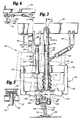
- a rail grinding machine 20 in accordance with the present invention broadly includes main frame 22 supported by rail engaging wheels 24, operator cab 26, equipment compartment 28, and a plurality of grinding assemblies 30.
- the rail engaging wheels 24 support the rail grinding machine 20 on railroad track 32.
- the track 32 comprises a pair of rails 34 stretching across ties 36 of railroad bed 37.
- Each grinding assembly 30 broadly includes a plurality of grinding modules 38 individually mounted on a grinding assembly undercarriage 40.
- Each grinding assembly undercarriage 40 includes a grinding module support frame 42 attached to the rail grinding machine main frame 22 by fore and aft telescoping struts 44, 46.
- Each grinding module 38 is suspended from support frame 42 by fore and aft brackets 48 and 50.
- fore and aft struts 44, 46 each include outer slide tube 52 pivotally coupled to main frame 22 by pivot pin 54, and an inner slide rod 56 slidably received within outer slide tube 52.
- the inner slide rod 56 includes lowermost base plate 58 attached to support frame 42 by bolts 60.
- Extensible boot 61 extends between outer slide tube 52 and the base plate 58 of the inner slide rod 56.
- Spreader piston and cylinder assemblies 62 extend between brackets 64 depending from the main frame 22 and the outer slide tube 52 of each fore and aft strut 44, 46.
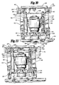
- Each grinding module support frame 42 includes fore and aft U-shaped support members 66, 68 interconnected by uppermost, gauge side and field side frame members 70, 72.
- Side to side braces 74, 76, 78 extend between the gauge side and the field side frame members 70, 72.
- a pair of fore and aft, horizontal slide rods 80, 82 extend between gauge side and field side frame members 70, 72 for slidable support of each grinding module 38.
- Fore and aft undercarriage elevation piston and cylinder assemblies 84 extend between brackets 86 depending from main frame 22 and the fore and aft U-shaped frame members 66, 68.
- Each grinding module 38 includes grinding motor 90 supported on grinding module base plate 92, grinding shaft 94, and grinding stone 96.
- the grinding shaft 94 defines a center grinding axis 97 for each grinding module.
- Grinding stones 96 are annular grinding wheels each having lowermost grinding surface 98, inner stone diameter 100, and outer stone diameter 102.
- Shiftable, fore and aft, grinding module support rods 104, 106 extend upwardly from base plate 92 of each grinding module 38.
- a grinding module top brace 108 extends between each fore and aft, vertical, grinding module support rod 104, 106.
- the vertical, grinding module support rods 104, 106 are received within fore and aft, vertical, grinding module support sleeves 110, 112.
- Gauge side shroud 114 extends between sleeves 110, 112.
- the fore and aft grinding module support sleeves 110, 112 are pivotally connected to respective fore and aft brackets 48, 50 by pivot supports 116, 118.
- a grinding module elevation piston and cylinder assembly 120 extends between the forward pivot support 116 and top brace 108 of each grinding module 38.
- each grinding module forward bracket 48 includes a tilt cylinder supporting brace 120.
- a grinding module tilting piston and cylinder assembly 122 extends between the brace 120 and the forward pivot support 116 of each respective grinding module.
- each of the fore and aft brackets 48, 50 are attached to a slide tube 124 carried by a respective fore or aft horizontal support rod 80, 82.
- a horizontal brace 125 extends between the slide tubes 124 of each pair of grinding module fore and aft support brackets 48, 50.
- a grinding module horizontal positioning piston and cylinder assembly 126 extends between each horizontal brace 125 and gauge side frame member 70.
- Each wheel assembly 128 includes rail engaging wheel 130 rotatably attached to a respective U-shaped frame member 66, 68 by pillow blocks 132, and guide roller assembly 134.
- Wheels 130 include rail top engaging surface 136 and side rail engaging flange 138.
- the rail top engaging surface 136 of each wheel 130 is of a standard width, comparable to the width of the rail head.
- Each guide roller assembly 134 includes a set down roller 139 rotatably supported by opposed gauge side and field side bearing plates 140, 142.
- the bearing plates 140, 142 are pivotally mounted to support brackets 144, 146 that extend downwardly from each U-shaped frame member 66, 68.
- a guide roller assembly piston and cylinder assembly 148 extends between the field side bearing plate 142 of each guide roller assembly 134 and a respective stanchion 149 carried by each fore and aft U-shaped frame member 66, 68.
- an upright securing flange 150 extends upwardly from each brace 74, 78.
- Securing flange receiving clevises 152 extend downwardly from main frame 42.
- Locking pins 154 are attached to locking pin actuating piston and cylinder assemblies 156 for shifting between securing flange engaging and securing flange clearing positions.
- grinding assemblies 30 of rail grinding machine 20 when not in use, are transported in raised, noncontacting relationship with the rails 34 of track 32, as depicted by phantom lines in Fig. 2 and Fig. 3.
- securing flanges 150 of grinding assembly undercarriage support frame 42 are secured within flange receiving clevises 152 of main frame 22 by locking pins 154, and the fore and aft struts 44, 46 are fully retracted.
- locking pins 154 are shifted to their securing flange clearing position, as depicted in Fig. 1.
- the spreading piston and cylinder assemblies 62 are fully extended so as to tilt the individual grinding assemblies 30 inwardly towards the gauge side of rails 34.
- the grinding assemblies 30 are lowered towards railroad track 36 by extending the undercarriage elevation piston and cylinder assemblies 84.
- the guide roller assemblies 134 Prior to lowering the grinding assemblies 30 towards the track 36, the guide roller assemblies 134 are pivoted downwardly by extending the guide roller piston and cylinder assemblies 148. Accordingly, the set down rollers 139 are the first members of the grinding assemblies 30 to come into contact with rails 34. Referring in particular to Fig. 6, it will be appreciated that the width of the guide rollers 139 ensures engagement of the guide rollers 139 with the rails 34, regardless of where the grinding assembly 30 is positioned by the spreader cylinders 62.
- the spreader piston and cylinder assemblies 62 can be retracted so as to shift the grinding assemblies 30 outwardly in a direction towards the field side of the rail 34.
- the rail engaging flange 138 of each wheel 130 will accordingly be brought into contact with the gauge side of rail 34.
- the guide roller piston and cylinder assemblies 148 can thereafter be retracted such that the weight of the grinding assembly 30 is borne by wheels 130. It will be understood, however, that an upward biasing force is exerted by the elevation piston and cylinder assemblies 86, 88 such that the entire weight of the grinding assembly 30 is not necessarily borne by the wheels 130.
- the spreader piston and cylinder assemblies 62 provide a constant biasing pressure to maintain the wheels 130 in engagement with rail 34.
- the top surface of rail 34 is ground by placing the grinding stone 96 directly over the rail 34, as depicted in Fig. 12a.
- the grinding axis of rotation 95 is centered along the longitudinal axis of rail 34.
- the rail 34 is contained between the inner diameter 100 of grinding stone 96, and grinding contact between the stone 96 and rail 34 is along a diameteral line d of the grinding stone 96.
- the grinding stone 96 is rotated as indicated by arrows R of Fig. 13, and is moved along the rail 34 in the direction of arrow A of Fig 13, the fine scratches S left on the rail 34 by the grinding action of the stone 96 are oriented perpendicular to the longitudinal axis of the rail 34.
- each grinding module 38 can be pivoted around pivot point P to position the grinding stone 96 at various tilt angles relative to the railhead.
- pivoting of the grinding module 38 around pivot point P without shifting of the pivot point laterally in relation to the longitudinal axis of the rail 34, shifts the line of grinding contact between the stone 96 and rail 34 from the center, diameteral line d of the grinding stone to a point outboard of the diameteral line d.
- tilting of the grinding module 38 to the orientation depicted in Fig. 12b enables shaping of the railhead
- the resultant shifting of the line of contact between the grinding stone 96 and the rail 34 away from the diameteral line d of stone 96 causes uneven wear of the stone 96.
- orientiation of the grinding stone 96 as depicted in Fig. 12b causes the scratches S left by the grinding operation to be transverse to the desired orientation perpendicular to the rail longitudinal axis.
- the grinding module 38 can be shifted laterally relative to the longitudinal axis of rail 34 by the extension and retraction of piston and cylinder assembly 126. More particularly, extension of respective horizontal positioning piston and cylinder assemblies 126 shifts the associated undercarriage 40 towards the field side of rail 34, the retraction of the piston and cylinder assembly 126 shifts the undercarriage 40 towards the gauge side of rail 34. Moreover, elevation of each individual grinding module 38 relative to the undercarriage 40 can be adjusted by the extension and retraction of respective module elevation piston and cylinder assemblies 120. Accordingly, the pivot point P can be shifted away from the center of rail 34, as depicted in Fig. 12c, and the grinding stone 96 can be lowered into contact with the rail 34 along a diameteral line d of the grinding stone 96.
- rail 34 is depicted in close proximity to an obstruction W.
- the obstruction could be a wooden support W placed along the rail at a highway crossing or the like.
- the presence of the obstruction W interferes with the placement of the grinding stone 96 relative to the rail 34.
- the capability to laterally shift the undercarriage 40 from side to side relative to the longitudinal axis of rail 34 provides a distinct advantage when grinding the rail 34 in the presence of an obstruction.
- pivot point P can be shifted laterally away from the obstruction W thereby allowing the grinding stone 96 to be tilted to a greater tilt angle while still avoiding the obstruction, than would otherwise be attainable.
- the grinding contact with the stone 96 with the rail 34 is, in the instance depicted in Fig. 12d, moved away from the diameteral line d of the grinding stone 96, the amount of grinding required to be done in the presence of an obstruction is typically minimal.
Landscapes
- Engineering & Computer Science (AREA)
- Mechanical Engineering (AREA)
- Architecture (AREA)
- Civil Engineering (AREA)
- Structural Engineering (AREA)
- Machines For Laying And Maintaining Railways (AREA)
- Polishing Bodies And Polishing Tools (AREA)
- Grinding Of Cylindrical And Plane Surfaces (AREA)
- Mechanical Treatment Of Semiconductor (AREA)
- Soil Working Implements (AREA)
- Spinning Or Twisting Of Yarns (AREA)
- Electrical Discharge Machining, Electrochemical Machining, And Combined Machining (AREA)
Priority Applications (1)
| Application Number | Priority Date | Filing Date | Title |
|---|---|---|---|
| AT88114215T ATE72850T1 (de) | 1987-08-31 | 1988-08-31 | Schienenschleifmaschine. |
Applications Claiming Priority (2)
| Application Number | Priority Date | Filing Date | Title |
|---|---|---|---|
| US07/091,231 US4862647A (en) | 1987-08-31 | 1987-08-31 | Rail grinding machine |
| US91231 | 1987-08-31 |
Related Child Applications (1)
| Application Number | Title | Priority Date | Filing Date |
|---|---|---|---|
| EP90111777.0 Division-Into | 1990-06-21 |
Publications (2)
| Publication Number | Publication Date |
|---|---|
| EP0304960A1 true EP0304960A1 (fr) | 1989-03-01 |
| EP0304960B1 EP0304960B1 (fr) | 1992-02-26 |
Family
ID=22226717
Family Applications (2)
| Application Number | Title | Priority Date | Filing Date |
|---|---|---|---|
| EP88114215A Expired - Lifetime EP0304960B1 (fr) | 1987-08-31 | 1988-08-31 | Machine à rectifier les rails |
| EP90111777A Expired - Lifetime EP0397215B1 (fr) | 1987-08-31 | 1988-08-31 | Machine de meulage de rails |
Family Applications After (1)
| Application Number | Title | Priority Date | Filing Date |
|---|---|---|---|
| EP90111777A Expired - Lifetime EP0397215B1 (fr) | 1987-08-31 | 1988-08-31 | Machine de meulage de rails |
Country Status (8)
| Country | Link |
|---|---|
| US (1) | US4862647A (fr) |
| EP (2) | EP0304960B1 (fr) |
| CN (1) | CN1032829A (fr) |
| AT (2) | ATE72850T1 (fr) |
| AU (1) | AU596319B2 (fr) |
| BR (1) | BR8804450A (fr) |
| CA (1) | CA1295835C (fr) |
| DE (2) | DE3868562D1 (fr) |
Cited By (5)
| Publication number | Priority date | Publication date | Assignee | Title |
|---|---|---|---|---|
| WO1994011153A1 (fr) * | 1992-11-06 | 1994-05-26 | Harsco Corporation | Dispositif de meulage de profils |
| FR2703084A1 (fr) * | 1993-03-25 | 1994-09-30 | Geismar Anc Ets L | Machine de meulage de rails d'une voie ferrée. |
| EP0665332A1 (fr) * | 1994-02-01 | 1995-08-02 | Franz Plasser Bahnbaumaschinen-Industriegesellschaft m.b.H. | Dispositif pour meuler des rails |
| EP0789108A1 (fr) * | 1996-02-06 | 1997-08-13 | Scheuchzer S.A. | Chariot équipé d'outils de meulage ou d'usinage pour le reprofilage de la surface de roulement et du champignon de rails de chemin de fer |
| WO2000058559A1 (fr) * | 1999-03-25 | 2000-10-05 | Wilfried Scherf | Dispositif de modules de meulage avec outils de meulage dans des machines a meuler les rails |
Families Citing this family (27)
| Publication number | Priority date | Publication date | Assignee | Title |
|---|---|---|---|---|
| CH680597A5 (fr) * | 1989-08-28 | 1992-09-30 | Speno International | |
| CA2071528A1 (fr) * | 1990-01-12 | 1991-07-13 | Alan L. Dzubak | Fermeture composite a garniture d'etancheite s'ajustant par serrage |
| CH685129A5 (fr) * | 1991-03-01 | 1995-03-31 | Speno International | Dispositif pour le reprofilage des rails d'une voie ferrée. |
| US5339692A (en) * | 1992-01-03 | 1994-08-23 | Loram Maintenance Of Way, Inc. | Ultrasonic rail web centerline detector |
| FR2696762B1 (fr) * | 1992-10-14 | 1994-12-30 | Geismar Anc Ets L | Procédé de meulage de la jonction bout-à-bout par soudage notamment de deux rails et machine de meulage pour la mise en Óoeuvre de ce procédé. |
| DE4316252C2 (de) * | 1993-05-14 | 1995-05-18 | Elektro Thermit Gmbh | Schienenschleifmaschine |
| EP0675227A1 (fr) * | 1994-03-30 | 1995-10-04 | Speno International S.A. | Machine pour la meulage de sections localisées d'un rail de chemin de fer, notamment des soudures d'abouts de rails ou autres défauts ponctuels |
| DE19518457A1 (de) * | 1995-05-19 | 1996-11-21 | Robel Georg Gmbh & Co | Vorrichtung zum Schleifen von Schienen |
| US6033291A (en) * | 1998-03-16 | 2000-03-07 | Loram Maintenance Of Way, Inc. | Offset rail grinding |
| US6425540B1 (en) * | 2000-02-29 | 2002-07-30 | Charles D. Morris | Method and apparatus for grinding rubber |
| AT410951B (de) * | 2000-07-17 | 2003-09-25 | Linsinger Maschinenbau Gmbh | Verfahren zum reprofilieren mindestens des fahrspiegels einer schiene sowie einrichtung hierzu |
| US6719616B2 (en) | 2000-09-08 | 2004-04-13 | Loram Maintenance Of Way, Inc. | Rail grinding apparatus |
| US7156723B2 (en) * | 2001-10-25 | 2007-01-02 | Loram Maintenance Of Way, Inc. | Method and apparatus for non-interrupted grinding of railroad crossing and main line track |
| US6981907B1 (en) * | 2004-11-03 | 2006-01-03 | Railworks Corporation | High angle grinder |
| US20120288342A1 (en) * | 2010-01-21 | 2012-11-15 | Helmut Rungger | Device for reworking the running surface of a rail head by machining |
| AT509530B1 (de) * | 2010-02-25 | 2012-01-15 | Linsinger Maschb Gesmbh | Fahrbare vorrichtung zum bearbeiten von schienenköpfen |
| US9617691B2 (en) | 2013-03-15 | 2017-04-11 | Greenleaf Technology Corporation | Rail re-profiling method and apparatus |
| EP2947204B1 (fr) * | 2014-05-19 | 2017-01-11 | Mevert Maschinenbau GmbH & Co.KG | Dispositif mobile de fraisage de champignons de rails et procédé de changement de plaques de coupe dans le cadre d'un tel dispositif |
| JP6667143B2 (ja) * | 2014-06-24 | 2020-03-18 | ファマ エス.アール.エル. | 接線研削機械 |
| CN104141265B (zh) * | 2014-07-30 | 2016-06-22 | 苏州市华宁机械制造有限公司 | 一种远程可视化水冷式铁轨侧面自动电动打磨装置 |
| CN104308235B (zh) * | 2014-09-26 | 2016-09-28 | 武汉利德测控技术股份有限公司 | 钢轨焊缝全断面铣削加工装置 |
| CN104480818A (zh) * | 2014-12-12 | 2015-04-01 | 苏州路云机电设备有限公司 | 一种砂轮前置楔块型肥边打磨机外部支撑杆 |
| JP6464066B2 (ja) * | 2015-09-18 | 2019-02-06 | 保線機器整備株式会社 | レール頭部削正機および自走式レール頭部削正装置 |
| CN105598513B (zh) * | 2016-03-28 | 2018-06-22 | 北京拓博尔轨道维护技术有限公司 | 钢轨铣削作业的控制方法 |
| CN110804911B (zh) * | 2019-11-25 | 2021-07-30 | 株洲时代电子技术有限公司 | 一种钢轨打磨单元 |
| CN110900365B (zh) * | 2019-11-25 | 2021-09-10 | 株洲时代电子技术有限公司 | 一种模块化钢轨打磨装置 |
| CN112176798A (zh) * | 2020-11-02 | 2021-01-05 | 浦江会亿智能科技有限公司 | 一种铁路检测修补设备 |
Citations (4)
| Publication number | Priority date | Publication date | Assignee | Title |
|---|---|---|---|---|
| GB776391A (en) * | 1955-02-17 | 1957-06-05 | Karl Heinz Schorling | Improvements in and relating to rail grinding devices especially for grinding railway rails |
| GB1151010A (en) * | 1967-08-08 | 1969-05-07 | Speno Internat S A | Machine for Deburring the Rails of Railway Track. |
| FR2206409A1 (fr) * | 1972-11-11 | 1974-06-07 | Elaugen Gmbh | |
| US4583327A (en) * | 1983-11-25 | 1986-04-22 | Jackson Jordan, Inc. | Rail grinding car |
Family Cites Families (13)
| Publication number | Priority date | Publication date | Assignee | Title |
|---|---|---|---|---|
| US3358406A (en) * | 1965-10-14 | 1967-12-19 | Speno International | Rail grinder |
| US3423858A (en) * | 1967-01-10 | 1969-01-28 | Speno International | Automatic control system for railway work apparatus |
| US3606705A (en) * | 1969-07-30 | 1971-09-21 | Speno International | Rail grinder |
| US3707808A (en) * | 1970-10-05 | 1973-01-02 | Mannix Construction Inc | Rail grinder |
| CH548488A (fr) * | 1972-06-08 | 1974-04-30 | Speno International | Procede de rectification en voie d'une file de rails par meulage de sa surface de roulement et dispositif pour la mise en oeuvre de ce procede. |
| US4189873A (en) * | 1975-02-25 | 1980-02-26 | Speno International S.A. | Machine for truing the bearing surface of the rails of a railroad track |
| CH606616A5 (fr) * | 1976-02-18 | 1978-11-15 | Speno International | |
| AT368219B (de) * | 1980-01-17 | 1982-09-27 | Plasser Bahnbaumasch Franz | Verfahren zum entfernen von unregelmaessigkeiten an der schienenkopfoberflaeche verlegter gleise |
| CH626673A5 (fr) * | 1980-07-23 | 1981-11-30 | Speno International | |
| CH666068A5 (fr) * | 1983-11-16 | 1988-06-30 | Speno International | Dispositif pour le reprofilage en continu du champignon d'au moins un rail. |
| CH655528B (fr) * | 1984-02-06 | 1986-04-30 | ||
| US4584798A (en) * | 1984-03-29 | 1986-04-29 | Speno Rail Services Co. | Automated railway track maintenance system |
| US4622781A (en) * | 1985-02-19 | 1986-11-18 | Loram Maintenance Of Way, Inc. | Rail grinding machine |
-
1987
- 1987-08-31 US US07/091,231 patent/US4862647A/en not_active Expired - Lifetime
-
1988
- 1988-05-04 CA CA000565896A patent/CA1295835C/fr not_active Expired - Lifetime
- 1988-08-30 AU AU21653/88A patent/AU596319B2/en not_active Expired
- 1988-08-31 DE DE8888114215T patent/DE3868562D1/de not_active Expired - Lifetime
- 1988-08-31 DE DE90111777T patent/DE3884967T2/de not_active Expired - Lifetime
- 1988-08-31 EP EP88114215A patent/EP0304960B1/fr not_active Expired - Lifetime
- 1988-08-31 AT AT88114215T patent/ATE72850T1/de not_active IP Right Cessation
- 1988-08-31 CN CN88107050A patent/CN1032829A/zh active Pending
- 1988-08-31 BR BR8804450A patent/BR8804450A/pt unknown
- 1988-08-31 AT AT90111777T patent/ATE95863T1/de not_active IP Right Cessation
- 1988-08-31 EP EP90111777A patent/EP0397215B1/fr not_active Expired - Lifetime
Patent Citations (4)
| Publication number | Priority date | Publication date | Assignee | Title |
|---|---|---|---|---|
| GB776391A (en) * | 1955-02-17 | 1957-06-05 | Karl Heinz Schorling | Improvements in and relating to rail grinding devices especially for grinding railway rails |
| GB1151010A (en) * | 1967-08-08 | 1969-05-07 | Speno Internat S A | Machine for Deburring the Rails of Railway Track. |
| FR2206409A1 (fr) * | 1972-11-11 | 1974-06-07 | Elaugen Gmbh | |
| US4583327A (en) * | 1983-11-25 | 1986-04-22 | Jackson Jordan, Inc. | Rail grinding car |
Cited By (9)
| Publication number | Priority date | Publication date | Assignee | Title |
|---|---|---|---|---|
| WO1994011153A1 (fr) * | 1992-11-06 | 1994-05-26 | Harsco Corporation | Dispositif de meulage de profils |
| US5359815A (en) * | 1992-11-06 | 1994-11-01 | Harsco Corporation | Profile grinder |
| FR2703084A1 (fr) * | 1993-03-25 | 1994-09-30 | Geismar Anc Ets L | Machine de meulage de rails d'une voie ferrée. |
| EP0665332A1 (fr) * | 1994-02-01 | 1995-08-02 | Franz Plasser Bahnbaumaschinen-Industriegesellschaft m.b.H. | Dispositif pour meuler des rails |
| EP0789108A1 (fr) * | 1996-02-06 | 1997-08-13 | Scheuchzer S.A. | Chariot équipé d'outils de meulage ou d'usinage pour le reprofilage de la surface de roulement et du champignon de rails de chemin de fer |
| WO2000058559A1 (fr) * | 1999-03-25 | 2000-10-05 | Wilfried Scherf | Dispositif de modules de meulage avec outils de meulage dans des machines a meuler les rails |
| JP2002541359A (ja) * | 1999-03-25 | 2002-12-03 | ヴィルフリート シャーフ, | 研摩工具を備えたレール研摩機用研摩モジュール装置 |
| US6638138B1 (en) | 1999-03-25 | 2003-10-28 | Michael Luddeneit | Arrangement of grinding modules with grinding tools in track grinders |
| JP4711370B2 (ja) * | 1999-03-25 | 2011-06-29 | ヴィルフリート シャーフ, | 研摩工具を備えたレール研摩機用研摩モジュール装置 |
Also Published As
| Publication number | Publication date |
|---|---|
| EP0397215A1 (fr) | 1990-11-14 |
| AU2165388A (en) | 1989-03-02 |
| CA1295835C (fr) | 1992-02-18 |
| DE3868562D1 (de) | 1992-04-02 |
| DE3884967T2 (de) | 1994-02-03 |
| CN1032829A (zh) | 1989-05-10 |
| US4862647A (en) | 1989-09-05 |
| DE3884967D1 (de) | 1993-11-18 |
| EP0304960B1 (fr) | 1992-02-26 |
| ATE72850T1 (de) | 1992-03-15 |
| BR8804450A (pt) | 1989-03-28 |
| EP0397215B1 (fr) | 1993-10-13 |
| ATE95863T1 (de) | 1993-10-15 |
| AU596319B2 (en) | 1990-04-26 |
Similar Documents
| Publication | Publication Date | Title |
|---|---|---|
| US4862647A (en) | Rail grinding machine | |
| SU1101176A3 (ru) | Передвижна машина дл контактной стыковой сварки оплавлением рельсов | |
| RU2062313C1 (ru) | Машина для ремонта или укладки железнодорожного пути | |
| EP0110246B1 (fr) | Machine à meuler des rails transportable sur un ou deux rails | |
| US20090193950A1 (en) | Automatic Rail Saw | |
| CA1299875C (fr) | Meuleuse de rails | |
| JP4713017B2 (ja) | 軌道更換装置 | |
| JPS6026882B2 (ja) | 路面兼軌道走行可能な軌道整正機械 | |
| US4622781A (en) | Rail grinding machine | |
| US3249067A (en) | Convertible railway-highway vehicle | |
| SK728088A3 (en) | Travelling tamping machine | |
| PL175034B1 (pl) | Maszyna do podbijania torów | |
| JPS6078002A (ja) | 走行可能な軌道整正機械 | |
| CA2206742C (fr) | Machine de pose de voies ferrees | |
| EP0603149B2 (fr) | Machine d'aspirateur | |
| US4152991A (en) | Ripping apparatus | |
| JPH0258601A (ja) | 軌道走行型レール設置/撤去装置 | |
| JPH10195805A (ja) | 鉄道線路のレール頭部上面の連続精密輪郭再研削装置 | |
| CA1295834C (fr) | Appareil et methode de meulage in situ des joints de soudure des patins de rail | |
| US4854088A (en) | In-track rail base grinding method | |
| US4746262A (en) | Apparatus for handling and transporting double frame structures | |
| US4486936A (en) | Apparatus for removing a roller or workpiece | |
| EP0524661A1 (fr) | Machine de meulage de rails | |
| EP0528444A1 (fr) | Machine de meulage de rails | |
| JP2850058B2 (ja) | 道床連続掘削積込機 |
Legal Events
| Date | Code | Title | Description |
|---|---|---|---|
| PUAI | Public reference made under article 153(3) epc to a published international application that has entered the european phase |
Free format text: ORIGINAL CODE: 0009012 |
|
| AK | Designated contracting states |
Kind code of ref document: A1 Designated state(s): AT BE CH DE ES FR GB IT LI SE |
|
| 17P | Request for examination filed |
Effective date: 19890616 |
|
| 17Q | First examination report despatched |
Effective date: 19900126 |
|
| GRAA | (expected) grant |
Free format text: ORIGINAL CODE: 0009210 |
|
| AK | Designated contracting states |
Kind code of ref document: B1 Designated state(s): AT BE CH DE ES FR GB IT LI SE |
|
| REF | Corresponds to: |
Ref document number: 72850 Country of ref document: AT Date of ref document: 19920315 Kind code of ref document: T |
|
| XX | Miscellaneous (additional remarks) |
Free format text: TEILANMELDUNG 90111777.0 EINGEREICHT AM 31/08/88. |
|
| ITF | It: translation for a ep patent filed |
Owner name: JACOBACCI & PERANI S.P.A. |
|
| ET | Fr: translation filed | ||
| REF | Corresponds to: |
Ref document number: 3868562 Country of ref document: DE Date of ref document: 19920402 |
|
| PG25 | Lapsed in a contracting state [announced via postgrant information from national office to epo] |
Ref country code: ES Free format text: LAPSE BECAUSE OF FAILURE TO SUBMIT A TRANSLATION OF THE DESCRIPTION OR TO PAY THE FEE WITHIN THE PRESCRIBED TIME-LIMIT Effective date: 19920606 |
|
| PGFP | Annual fee paid to national office [announced via postgrant information from national office to epo] |
Ref country code: ES Payment date: 19920812 Year of fee payment: 5 |
|
| PLBE | No opposition filed within time limit |
Free format text: ORIGINAL CODE: 0009261 |
|
| STAA | Information on the status of an ep patent application or granted ep patent |
Free format text: STATUS: NO OPPOSITION FILED WITHIN TIME LIMIT |
|
| 26N | No opposition filed | ||
| PGFP | Annual fee paid to national office [announced via postgrant information from national office to epo] |
Ref country code: SE Payment date: 19930806 Year of fee payment: 6 |
|
| PGFP | Annual fee paid to national office [announced via postgrant information from national office to epo] |
Ref country code: CH Payment date: 19930825 Year of fee payment: 6 |
|
| PGFP | Annual fee paid to national office [announced via postgrant information from national office to epo] |
Ref country code: BE Payment date: 19930909 Year of fee payment: 6 |
|
| PG25 | Lapsed in a contracting state [announced via postgrant information from national office to epo] |
Ref country code: BE Effective date: 19940831 Ref country code: LI Effective date: 19940831 Ref country code: CH Effective date: 19940831 |
|
| PG25 | Lapsed in a contracting state [announced via postgrant information from national office to epo] |
Ref country code: SE Effective date: 19940901 |
|
| EAL | Se: european patent in force in sweden |
Ref document number: 88114215.2 |
|
| BERE | Be: lapsed |
Owner name: LORAM MAINTENANCE OF WAY INC. Effective date: 19940831 |
|
| REG | Reference to a national code |
Ref country code: CH Ref legal event code: PL |
|
| EUG | Se: european patent has lapsed |
Ref document number: 88114215.2 |
|
| REG | Reference to a national code |
Ref country code: GB Ref legal event code: IF02 |
|
| PGFP | Annual fee paid to national office [announced via postgrant information from national office to epo] |
Ref country code: FR Payment date: 20060808 Year of fee payment: 19 |
|
| PGFP | Annual fee paid to national office [announced via postgrant information from national office to epo] |
Ref country code: DE Payment date: 20070830 Year of fee payment: 20 |
|
| PGFP | Annual fee paid to national office [announced via postgrant information from national office to epo] |
Ref country code: AT Payment date: 20070829 Year of fee payment: 20 |
|
| PGFP | Annual fee paid to national office [announced via postgrant information from national office to epo] |
Ref country code: GB Payment date: 20070829 Year of fee payment: 20 |
|
| PGFP | Annual fee paid to national office [announced via postgrant information from national office to epo] |
Ref country code: IT Payment date: 20070830 Year of fee payment: 20 |
|
| REG | Reference to a national code |
Ref country code: FR Ref legal event code: ST Effective date: 20080430 |
|
| REG | Reference to a national code |
Ref country code: GB Ref legal event code: PE20 Expiry date: 20080830 |
|
| PG25 | Lapsed in a contracting state [announced via postgrant information from national office to epo] |
Ref country code: FR Free format text: LAPSE BECAUSE OF NON-PAYMENT OF DUE FEES Effective date: 20070831 |
|
| PG25 | Lapsed in a contracting state [announced via postgrant information from national office to epo] |
Ref country code: GB Free format text: LAPSE BECAUSE OF EXPIRATION OF PROTECTION Effective date: 20080830 |