EP0303902A2 - Dispositif pour le raccordement d'éléments cylindriques - Google Patents
Dispositif pour le raccordement d'éléments cylindriques Download PDFInfo
- Publication number
- EP0303902A2 EP0303902A2 EP88112687A EP88112687A EP0303902A2 EP 0303902 A2 EP0303902 A2 EP 0303902A2 EP 88112687 A EP88112687 A EP 88112687A EP 88112687 A EP88112687 A EP 88112687A EP 0303902 A2 EP0303902 A2 EP 0303902A2
- Authority
- EP
- European Patent Office
- Prior art keywords
- tensioning
- band
- components
- tension
- clamping
- Prior art date
- Legal status (The legal status is an assumption and is not a legal conclusion. Google has not performed a legal analysis and makes no representation as to the accuracy of the status listed.)
- Granted
Links
Images

Classifications
-
- F—MECHANICAL ENGINEERING; LIGHTING; HEATING; WEAPONS; BLASTING
- F16—ENGINEERING ELEMENTS AND UNITS; GENERAL MEASURES FOR PRODUCING AND MAINTAINING EFFECTIVE FUNCTIONING OF MACHINES OR INSTALLATIONS; THERMAL INSULATION IN GENERAL
- F16B—DEVICES FOR FASTENING OR SECURING CONSTRUCTIONAL ELEMENTS OR MACHINE PARTS TOGETHER, e.g. NAILS, BOLTS, CIRCLIPS, CLAMPS, CLIPS OR WEDGES; JOINTS OR JOINTING
- F16B2/00—Friction-grip releasable fastenings
- F16B2/02—Clamps, i.e. with gripping action effected by positive means other than the inherent resistance to deformation of the material of the fastening
- F16B2/06—Clamps, i.e. with gripping action effected by positive means other than the inherent resistance to deformation of the material of the fastening external, i.e. with contracting action
- F16B2/08—Clamps, i.e. with gripping action effected by positive means other than the inherent resistance to deformation of the material of the fastening external, i.e. with contracting action using bands
-
- B—PERFORMING OPERATIONS; TRANSPORTING
- B64—AIRCRAFT; AVIATION; COSMONAUTICS
- B64G—COSMONAUTICS; VEHICLES OR EQUIPMENT THEREFOR
- B64G1/00—Cosmonautic vehicles
- B64G1/22—Parts of, or equipment specially adapted for fitting in or to, cosmonautic vehicles
- B64G1/64—Systems for coupling or separating cosmonautic vehicles or parts thereof, e.g. docking arrangements
- B64G1/641—Interstage or payload connectors
- B64G1/642—Clamps, e.g. Marman clamps
-
- B—PERFORMING OPERATIONS; TRANSPORTING
- B64—AIRCRAFT; AVIATION; COSMONAUTICS
- B64G—COSMONAUTICS; VEHICLES OR EQUIPMENT THEREFOR
- B64G1/00—Cosmonautic vehicles
- B64G1/22—Parts of, or equipment specially adapted for fitting in or to, cosmonautic vehicles
- B64G1/64—Systems for coupling or separating cosmonautic vehicles or parts thereof, e.g. docking arrangements
- B64G1/645—Separators
- B64G1/6457—Springs; Shape memory actuators
-
- F—MECHANICAL ENGINEERING; LIGHTING; HEATING; WEAPONS; BLASTING
- F16—ENGINEERING ELEMENTS AND UNITS; GENERAL MEASURES FOR PRODUCING AND MAINTAINING EFFECTIVE FUNCTIONING OF MACHINES OR INSTALLATIONS; THERMAL INSULATION IN GENERAL
- F16L—PIPES; JOINTS OR FITTINGS FOR PIPES; SUPPORTS FOR PIPES, CABLES OR PROTECTIVE TUBING; MEANS FOR THERMAL INSULATION IN GENERAL
- F16L23/00—Flanged joints
- F16L23/04—Flanged joints the flanges being connected by members tensioned in the radial plane
- F16L23/08—Flanged joints the flanges being connected by members tensioned in the radial plane connection by tangentially arranged pin and nut
-
- F—MECHANICAL ENGINEERING; LIGHTING; HEATING; WEAPONS; BLASTING
- F16—ENGINEERING ELEMENTS AND UNITS; GENERAL MEASURES FOR PRODUCING AND MAINTAINING EFFECTIVE FUNCTIONING OF MACHINES OR INSTALLATIONS; THERMAL INSULATION IN GENERAL
- F16L—PIPES; JOINTS OR FITTINGS FOR PIPES; SUPPORTS FOR PIPES, CABLES OR PROTECTIVE TUBING; MEANS FOR THERMAL INSULATION IN GENERAL
- F16L33/00—Arrangements for connecting hoses to rigid members; Rigid hose-connectors, i.e. single members engaging both hoses
- F16L33/02—Hose-clips
- F16L33/04—Hose-clips tightened by tangentially-arranged threaded pin and nut
-
- Y—GENERAL TAGGING OF NEW TECHNOLOGICAL DEVELOPMENTS; GENERAL TAGGING OF CROSS-SECTIONAL TECHNOLOGIES SPANNING OVER SEVERAL SECTIONS OF THE IPC; TECHNICAL SUBJECTS COVERED BY FORMER USPC CROSS-REFERENCE ART COLLECTIONS [XRACs] AND DIGESTS
- Y10—TECHNICAL SUBJECTS COVERED BY FORMER USPC
- Y10T—TECHNICAL SUBJECTS COVERED BY FORMER US CLASSIFICATION
- Y10T24/00—Buckles, buttons, clasps, etc.
- Y10T24/14—Bale and package ties, hose clamps
- Y10T24/1412—Bale and package ties, hose clamps with tighteners
- Y10T24/1441—Tangential screw
- Y10T24/1449—Wire
-
- Y—GENERAL TAGGING OF NEW TECHNOLOGICAL DEVELOPMENTS; GENERAL TAGGING OF CROSS-SECTIONAL TECHNOLOGIES SPANNING OVER SEVERAL SECTIONS OF THE IPC; TECHNICAL SUBJECTS COVERED BY FORMER USPC CROSS-REFERENCE ART COLLECTIONS [XRACs] AND DIGESTS
- Y10—TECHNICAL SUBJECTS COVERED BY FORMER USPC
- Y10T—TECHNICAL SUBJECTS COVERED BY FORMER US CLASSIFICATION
- Y10T24/00—Buckles, buttons, clasps, etc.
- Y10T24/44—Clasp, clip, support-clamp, or required component thereof
- Y10T24/44239—Encircling gripping member including semirigid band and operator for tightening
Definitions
- the invention relates to a device for connecting cylindrical components in the form of an at least partially consisting of two parallel strands of tension band, which comprises the areas of the components to be connected and which is guided around the bolt arranged perpendicular to the direction of tension of the tension band, in which in the closed position the one another areas of the band to be tensioned are arranged to overlap one another and opposing bolts are detachably connected to one another via a pressure tensioning element.
- Devices of this type are frequently used in the field of space technology to hold payloads on the final stages of launchers and to release them when the intended orbits are reached by detonating the tensioning element.
- Devices of the type mentioned at the outset are also used for this purpose, which are referred to as Marman tension band connections and in which a number of clamp elements are arranged on the inside of the tension band.
- Such clamp elements have conical recesses on their inside and engage with them via appropriately shaped flanges or interface rings which are arranged on the end regions of the individual components to be connected.
- the object of the invention is to design a device of the type mentioned in such a way that it is as small as possible Dead weight has a high load-bearing capacity and that it can be used for the widest possible range of component diameters.
- the invention solves the problem by providing that clip elements are provided on the inside of the tension band, which are provided with recesses which engage positively over flange-like, peripherally arranged approaches of the components and that the clip elements are arranged in those areas of the tension band that are divided.
- the intended use of two tensioning belts or tensioning ropes arranged symmetrically to the compression tensioning element can be further optimized by distributing the occurring forces.
- This measure is particularly in connection with the use of the mentioned clamp elements is advantageous because it reliably prevents bending of the entire connection.
- the operating loads tolerated by the device according to the invention are increased again and their use is made possible even with very large component diameters. This measure also results in additional weight savings.
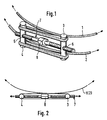
- a connecting device in the manner of a tensioning band is formed by two tensioning cables 1 and 2, which run at a parallel distance from one another.
- the endless tensioning cables 1 and 2 are wrapped around two connecting bolts 3 and 4, which lie parallel to the longitudinal axis of the cylindrical components, not shown, to be connected to one another.
- the connecting bolts 3 and 4 are each provided with centrally arranged and transverse threaded holes 5 and 6, in which a pressure clamping screw 7 engages, which lies symmetrically between the tensioning cables 1 and 2.
- the distance between the two connecting bolts 3 and 4 can be changed so far that in the two tension cables 1 and 2 the tension required to ensure a secure connection.
- the force distribution that occurs is indicated by arrows in FIG. 2.
- the simply drawn arrows symbolize tensile forces, while the double-drawn arrows symbolize the pressure forces exerted by the pressure clamping screw 7 on the connecting bolts 3 and 4.
- FIG. 3 is a second exemplary embodiment of a connecting device for cylindrical components.
- a one-piece tension belt 11 which is guided around a connection bolt 12, and a tension band consisting of two tension belts 13 and 14 overlap.
- the two straps 13 and 14 are guided around a second connecting pin 15.
- the two connecting bolts 12 and 15 are each provided with central transverse threaded bores 16 and 17, into which a pressure screw, not shown in the figure, can be inserted, analogously to the pressure screw 7 in FIG. 1.
- the compression tensioning screw also extends through a recess 18 in the one-piece tensioning belt 11.
- connection area of two components 21 and 22 to be connected in this area which are cylindrical in shape in this area.
- the two end areas of the two components are each provided with flanges or interface rings 23 and 24 which are conically shaped on one side.
- Each clamp element 25 has on its inside a conical recess 28 which is adapted to the shape of the flanges or interface rings 23 and 24.
- the clamp elements 25 which are arranged equidistantly over the circumference of the tensioning cables 26 and 27, are pressed against the connection point as a result of the tension present in these cables and thus press the two flanges or interface rings 23 and 24 against one another. Since the two tensioning cables 26 and 27 engage at a distance above or below the connection point, bending of the clamp elements 25 and thus gaping apart of the two flanges under the operating load are prevented.
- FIG. 5 differs from the one described above in that instead of the tension cables, two tension belts 31 and 32 are provided in this case, on which clamp elements 33 are held. In this case, too, two flanges or interface rings 35, 36, which are arranged on cylindrical components 37 and 38, are held together by the conical recess 34 of the clamp elements 33.
- Tension belts 31 and 32 shown in this figure correspond to tension belts 13 and 14 in FIG. 2.
- the tensioning strap device described above can be used for practically all diameters on interface rings or flanges. This also includes those with very large diameters, in which, due to the problems described, the use of such tension band connections was previously not considered possible and instead more complex and, above all, heavier connection devices were used.
- the required strengths the occurrence of any bending moments on the interface rings need not be taken into account when using the arrangement described above. Rather, the interface rings enclosed by the tensioning cables or tensioning straps form a system of high load-bearing capacity, which is essentially only limited by the strength of the interface rings or flanges.
- FIG. 3 is also particularly suitable for two or more tensioning elements, areas being able to alternate only with one tensioning strap and with two tensioning straps and clip elements are used, for example, only in the areas in which two tensioning straps are provided.
- the tension in the tensioning ropes or tensioning straps can be kept almost constant and the influence of friction can thus be minimized.
Landscapes
- Engineering & Computer Science (AREA)
- General Engineering & Computer Science (AREA)
- Mechanical Engineering (AREA)
- Remote Sensing (AREA)
- Aviation & Aerospace Engineering (AREA)
- Clamps And Clips (AREA)
Applications Claiming Priority (2)
| Application Number | Priority Date | Filing Date | Title |
|---|---|---|---|
| DE3727448 | 1987-08-18 | ||
| DE3727448A DE3727448C2 (de) | 1987-08-18 | 1987-08-18 | Vorrichtung zum Verbinden zylindrischer Bauteile |
Publications (3)
| Publication Number | Publication Date |
|---|---|
| EP0303902A2 true EP0303902A2 (fr) | 1989-02-22 |
| EP0303902A3 EP0303902A3 (en) | 1989-10-18 |
| EP0303902B1 EP0303902B1 (fr) | 1992-07-22 |
Family
ID=6333946
Family Applications (1)
| Application Number | Title | Priority Date | Filing Date |
|---|---|---|---|
| EP88112687A Expired - Lifetime EP0303902B1 (fr) | 1987-08-18 | 1988-08-04 | Dispositif pour le raccordement d'éléments cylindriques |
Country Status (4)
| Country | Link |
|---|---|
| US (1) | US5157816A (fr) |
| EP (1) | EP0303902B1 (fr) |
| JP (1) | JP2532923B2 (fr) |
| DE (1) | DE3727448C2 (fr) |
Cited By (4)
| Publication number | Priority date | Publication date | Assignee | Title |
|---|---|---|---|---|
| WO1994010513A1 (fr) * | 1992-10-27 | 1994-05-11 | Level Energietechniek B.V. | Appareil de reception de radiations solaires et son procede de preparation |
| NL9300120A (nl) * | 1993-01-21 | 1994-08-16 | Woerd Bv | Inrichting voor het bevestigen van een voorwerp op een buis, in het bijzonder voor het bevestigen van een voorwerp op een stuur van een tweewieler. |
| WO2004072490A3 (fr) * | 2003-02-11 | 2004-09-23 | J S Tec | Dispositif d'ancrage positionnable a tout endroit d'un support allonge de section quelconque |
| WO2013156830A1 (fr) * | 2012-04-20 | 2013-10-24 | Straub Werke Ag | Courroie de serrage et accouplement pour la liaison à force de tuyaux, en particulier de tuyaux à extrémité lisse |
Families Citing this family (17)
| Publication number | Priority date | Publication date | Assignee | Title |
|---|---|---|---|---|
| US5809623A (en) * | 1997-08-06 | 1998-09-22 | Delaware Capital Formation, Inc. | Squeeze clamp |
| DE10033093B4 (de) | 2000-07-07 | 2005-03-03 | Eads Space Transportation Gmbh | Vorrichtung zum lösbaren verbinden rotationssystemmetrischer Bauteile |
| DE10301783B4 (de) * | 2003-01-18 | 2005-04-28 | Eads Space Transp Gmbh | Vorrichtung zum lösbaren Verbinden rotationssymmetrischer Bauteile |
| US7056073B2 (en) * | 2003-03-12 | 2006-06-06 | Ardo Louis D | Load securing device and method for using the same |
| SG125980A1 (en) * | 2005-03-15 | 2006-10-30 | Goh Peng Chew | Fastening mechanism |
| ATE520595T1 (de) * | 2005-10-06 | 2011-09-15 | Eads Casa Espacio S L | Vorrichtung zur verbindung/trennung eines abschussfahrzeugs mit/von einem satelliten |
| FR2974566B1 (fr) * | 2011-04-26 | 2013-12-27 | Astrium Sas | Procede de liaison temporaire entre deux pieces, telles que deux etages d'un lanceur spatial, et ensemble de deux pieces reliees temporairement |
| US10190537B2 (en) | 2013-07-02 | 2019-01-29 | Mra Systems, Inc. | Engine and band clamp |
| CA2868597C (fr) | 2014-10-21 | 2020-09-29 | Wellsite Guard Ltd. | Pare-pluie destine au bassin de confinement de boite de garniture de puits de petrole |
| GB2541980B (en) * | 2015-09-02 | 2018-02-07 | Romax Tech Limited | Bearing compression strap |
| SE540399C2 (sv) * | 2016-04-20 | 2018-09-11 | Bae Systems Bofors Ab | Stödanordning för delningsbar fallskärmsgranat |
| US10514119B2 (en) * | 2016-11-22 | 2019-12-24 | Schauenburg Flexadux Corporation | Duct coupling system |
| CN108050351B (zh) * | 2017-12-08 | 2020-01-10 | 中国科学院长春光学精密机械与物理研究所 | 一种可解锁式空间遥感相机支架 |
| FR3096033B1 (fr) * | 2019-05-14 | 2021-05-28 | Spirit Tech | Système d’accouplement circonférentiel, notamment pour un accouplement d’un satellite et d’un porte-satellite |
| CN111114853B (zh) * | 2019-12-24 | 2021-04-20 | 兰州空间技术物理研究所 | 一种空间飞行器用可主动导热的对接锁紧接口装置 |
| CN111056052B (zh) * | 2019-12-31 | 2021-04-20 | 中国科学院空间应用工程与技术中心 | 一种在轨载荷模块重复锁紧释放机构 |
| JP7530570B2 (ja) * | 2020-11-20 | 2024-08-08 | 中国電力株式会社 | 装柱バンド |
Family Cites Families (21)
| Publication number | Priority date | Publication date | Assignee | Title |
|---|---|---|---|---|
| US3104898A (en) * | 1963-09-24 | Tube couplers | ||
| GB591284A (en) * | 1945-02-02 | 1947-08-13 | William Wilson Hamill | Means for clamping together two adjacent members |
| US1432572A (en) * | 1921-06-22 | 1922-10-17 | Henry A Schroeder | Hose clamp |
| US1468297A (en) * | 1923-01-05 | 1923-09-18 | Hogg John Steadman | Clip for pipes or tubes |
| GB454009A (en) * | 1935-01-17 | 1936-09-17 | Marcel Urbain Caillau | Hose clamp |
| GB573695A (en) * | 1943-08-17 | 1945-12-03 | Robert Cuthbert Scott Jamie | Improvements in or relating to metal hose clips |
| US2561635A (en) * | 1948-08-02 | 1951-07-24 | Carroll W Prochaska | Hose clamp |
| BE511690A (fr) * | 1951-05-28 | |||
| US3029095A (en) * | 1955-08-18 | 1962-04-10 | Garrett Corp | Flange connecting clamp |
| GB885996A (en) * | 1958-09-23 | 1962-01-03 | Kac Ltd | Improvements relating to pipe, hose and like couplings |
| US3359018A (en) * | 1965-06-24 | 1967-12-19 | Sta Rite Industries | Pipe coupling |
| FR1543373A (fr) * | 1967-09-08 | 1968-10-25 | Collier de serrage | |
| CH534311A (de) * | 1971-02-25 | 1973-02-28 | Von Roll Ag | Bride |
| GB1393555A (en) * | 1972-12-13 | 1975-05-07 | Canning Brett Ltd | Band clips for hoses and pipes |
| US3861723A (en) * | 1973-08-28 | 1975-01-21 | Us Air Force | V-band coupling |
| JPS5316200A (en) * | 1976-07-30 | 1978-02-14 | Hitachi Ltd | Core water purifying device for boiling water type reactor |
| JPS5334400A (en) * | 1976-10-25 | 1978-03-30 | Naka Tech Lab | Escaping device for building |
| DE2655772C3 (de) * | 1976-12-09 | 1980-07-31 | Messerschmitt-Boelkow-Blohm Gmbh, 8000 Muenchen | Spannband mit beweglichen Spannklötzen |
| US4527818A (en) * | 1981-02-17 | 1985-07-09 | Texaco Inc. | Coupling for pipe or tubing |
| US4489464A (en) * | 1982-07-07 | 1984-12-25 | Renzo Massari | U-Profiled improved hose clamp |
| JPS61287900A (ja) * | 1985-06-15 | 1986-12-18 | 日産自動車株式会社 | 補助ブ−スタの取付構造 |
-
1987
- 1987-08-18 DE DE3727448A patent/DE3727448C2/de not_active Expired - Fee Related
-
1988
- 1988-08-04 EP EP88112687A patent/EP0303902B1/fr not_active Expired - Lifetime
- 1988-08-12 JP JP63200325A patent/JP2532923B2/ja not_active Expired - Fee Related
-
1990
- 1990-07-09 US US07/549,535 patent/US5157816A/en not_active Expired - Lifetime
Cited By (7)
| Publication number | Priority date | Publication date | Assignee | Title |
|---|---|---|---|---|
| WO1994010513A1 (fr) * | 1992-10-27 | 1994-05-11 | Level Energietechniek B.V. | Appareil de reception de radiations solaires et son procede de preparation |
| NL9300120A (nl) * | 1993-01-21 | 1994-08-16 | Woerd Bv | Inrichting voor het bevestigen van een voorwerp op een buis, in het bijzonder voor het bevestigen van een voorwerp op een stuur van een tweewieler. |
| WO2004072490A3 (fr) * | 2003-02-11 | 2004-09-23 | J S Tec | Dispositif d'ancrage positionnable a tout endroit d'un support allonge de section quelconque |
| WO2013156830A1 (fr) * | 2012-04-20 | 2013-10-24 | Straub Werke Ag | Courroie de serrage et accouplement pour la liaison à force de tuyaux, en particulier de tuyaux à extrémité lisse |
| CN104160196A (zh) * | 2012-04-20 | 2014-11-19 | 瑞士斯特劳勃管道接头有限公司 | 紧合皮带以及用于力锁合地连接管、特别是平端管的管联接件 |
| CN104160196B (zh) * | 2012-04-20 | 2016-05-11 | 瑞士斯特劳勃管道接头有限公司 | 紧合皮带以及用于力锁合地连接管、特别是平端管的管联接件 |
| US9631748B2 (en) | 2012-04-20 | 2017-04-25 | Straub Werke Ag | Clamping belt and pipe coupling for the force-closed connection of pipes, in particular of smooth-end pipes |
Also Published As
| Publication number | Publication date |
|---|---|
| DE3727448A1 (de) | 1989-03-02 |
| EP0303902A3 (en) | 1989-10-18 |
| JPS6483499A (en) | 1989-03-29 |
| JP2532923B2 (ja) | 1996-09-11 |
| EP0303902B1 (fr) | 1992-07-22 |
| DE3727448C2 (de) | 1994-10-13 |
| US5157816A (en) | 1992-10-27 |
Similar Documents
| Publication | Publication Date | Title |
|---|---|---|
| EP0303902A2 (fr) | Dispositif pour le raccordement d'éléments cylindriques | |
| DE29605115U1 (de) | Gurtaufroller | |
| EP1170539B1 (fr) | Dispositif pour la connexion amovible des pièces symétriques de révolution | |
| DE2440587B2 (de) | Verankerungsvorrichtung fuer spannbetonbauteile | |
| EP0145646A2 (fr) | Dispositif de liaison de membres, de dispositifs tendeurs et/ou de contrôle avec des sangles | |
| DE2114006C3 (de) | Verstärkungseinlage für Bänder oder Riemen, insbesondere Förderbänder | |
| DE3640695A1 (de) | Vorrichtung zum fixieren von faserfoermigen zugentlastungsschichten insbesondere bei lichtwellenleiterkabeln | |
| DE3725036C2 (fr) | ||
| AT391916B (de) | Ausleger mit horizontaler seilabspannung | |
| EP4199212A1 (fr) | Ensemble batterie comprenant des modules de batterie et des bandes de serrage pour la fixation, véhicule automobile doté d'un ensemble batterie | |
| DE3623399C1 (en) | Totally insulated anchor clamp (tension clamp, dead-end clamp) | |
| DE2646998A1 (de) | Gurtkraftbegrenzer fuer fahrzeugsicherheitsgurte | |
| WO2021032351A1 (fr) | Dispositif et procédé permettant le serrage d'un empilement de piles à combustible | |
| DE102020108930A1 (de) | Lösbare Seilendverbindung für hochmodulare Faserseile | |
| DE3638179C2 (de) | Lösbare Verbindung für die Stuhlung einer Papiermaschine | |
| DE2440587C2 (de) | Verankerungsvorrichtung für Spannbetonbauteile | |
| AT3805U1 (de) | Dämpfungseinrichtung für eine seilbahn | |
| DE3539392A1 (de) | Klemmvorrichtung, insbesondere zum befestigen eines starkstromkabels an einem isolator | |
| DE9300483U1 (de) | Endverbindung für ein Drahtseil | |
| DE202024102227U1 (de) | Spiralkabel mit fixierten Kabelwindungen | |
| DE3423382A1 (de) | Arretiervorrichtung fuer einen sicherheitsgurt | |
| DE102008018094A1 (de) | Dämpfungsanordnung | |
| DE102021205907A1 (de) | Verbindung | |
| DE29804260U1 (de) | Umlenkbeschlag für einen Sicherheitsgurt | |
| DE102021131273A1 (de) | Kettenglied einer Leitungsführungseinrichtung mit Zugentlastung |
Legal Events
| Date | Code | Title | Description |
|---|---|---|---|
| PUAI | Public reference made under article 153(3) epc to a published international application that has entered the european phase |
Free format text: ORIGINAL CODE: 0009012 |
|
| AK | Designated contracting states |
Kind code of ref document: A2 Designated state(s): FR GB IT NL |
|
| 17P | Request for examination filed |
Effective date: 19890622 |
|
| PUAL | Search report despatched |
Free format text: ORIGINAL CODE: 0009013 |
|
| AK | Designated contracting states |
Kind code of ref document: A3 Designated state(s): FR GB IT NL |
|
| 17Q | First examination report despatched |
Effective date: 19901205 |
|
| GRAA | (expected) grant |
Free format text: ORIGINAL CODE: 0009210 |
|
| AK | Designated contracting states |
Kind code of ref document: B1 Designated state(s): FR GB IT NL |
|
| ET | Fr: translation filed | ||
| ITF | It: translation for a ep patent filed | ||
| GBT | Gb: translation of ep patent filed (gb section 77(6)(a)/1977) | ||
| PLBE | No opposition filed within time limit |
Free format text: ORIGINAL CODE: 0009261 |
|
| STAA | Information on the status of an ep patent application or granted ep patent |
Free format text: STATUS: NO OPPOSITION FILED WITHIN TIME LIMIT |
|
| 26N | No opposition filed | ||
| REG | Reference to a national code |
Ref country code: GB Ref legal event code: IF02 |
|
| PGFP | Annual fee paid to national office [announced via postgrant information from national office to epo] |
Ref country code: GB Payment date: 20040712 Year of fee payment: 17 |
|
| PGFP | Annual fee paid to national office [announced via postgrant information from national office to epo] |
Ref country code: FR Payment date: 20040830 Year of fee payment: 17 |
|
| PGFP | Annual fee paid to national office [announced via postgrant information from national office to epo] |
Ref country code: NL Payment date: 20040831 Year of fee payment: 17 |
|
| PG25 | Lapsed in a contracting state [announced via postgrant information from national office to epo] |
Ref country code: IT Free format text: LAPSE BECAUSE OF NON-PAYMENT OF DUE FEES;WARNING: LAPSES OF ITALIAN PATENTS WITH EFFECTIVE DATE BEFORE 2007 MAY HAVE OCCURRED AT ANY TIME BEFORE 2007. THE CORRECT EFFECTIVE DATE MAY BE DIFFERENT FROM THE ONE RECORDED. Effective date: 20050804 Ref country code: GB Free format text: LAPSE BECAUSE OF NON-PAYMENT OF DUE FEES Effective date: 20050804 |
|
| PG25 | Lapsed in a contracting state [announced via postgrant information from national office to epo] |
Ref country code: NL Free format text: LAPSE BECAUSE OF NON-PAYMENT OF DUE FEES Effective date: 20060301 |
|
| GBPC | Gb: european patent ceased through non-payment of renewal fee |
Effective date: 20050804 |
|
| PG25 | Lapsed in a contracting state [announced via postgrant information from national office to epo] |
Ref country code: FR Free format text: LAPSE BECAUSE OF NON-PAYMENT OF DUE FEES Effective date: 20060428 |
|
| NLV4 | Nl: lapsed or anulled due to non-payment of the annual fee |
Effective date: 20060301 |
|
| REG | Reference to a national code |
Ref country code: FR Ref legal event code: ST Effective date: 20060428 |