EP0303902A2 - Device for connecting cylindrical elements - Google Patents
Device for connecting cylindrical elements Download PDFInfo
- Publication number
- EP0303902A2 EP0303902A2 EP88112687A EP88112687A EP0303902A2 EP 0303902 A2 EP0303902 A2 EP 0303902A2 EP 88112687 A EP88112687 A EP 88112687A EP 88112687 A EP88112687 A EP 88112687A EP 0303902 A2 EP0303902 A2 EP 0303902A2
- Authority
- EP
- European Patent Office
- Prior art keywords
- tensioning
- band
- components
- tension
- clamping
- Prior art date
- Legal status (The legal status is an assumption and is not a legal conclusion. Google has not performed a legal analysis and makes no representation as to the accuracy of the status listed.)
- Granted
Links
Images

Classifications
-
- F—MECHANICAL ENGINEERING; LIGHTING; HEATING; WEAPONS; BLASTING
- F16—ENGINEERING ELEMENTS AND UNITS; GENERAL MEASURES FOR PRODUCING AND MAINTAINING EFFECTIVE FUNCTIONING OF MACHINES OR INSTALLATIONS; THERMAL INSULATION IN GENERAL
- F16B—DEVICES FOR FASTENING OR SECURING CONSTRUCTIONAL ELEMENTS OR MACHINE PARTS TOGETHER, e.g. NAILS, BOLTS, CIRCLIPS, CLAMPS, CLIPS OR WEDGES; JOINTS OR JOINTING
- F16B2/00—Friction-grip releasable fastenings
- F16B2/02—Clamps, i.e. with gripping action effected by positive means other than the inherent resistance to deformation of the material of the fastening
- F16B2/06—Clamps, i.e. with gripping action effected by positive means other than the inherent resistance to deformation of the material of the fastening external, i.e. with contracting action
- F16B2/08—Clamps, i.e. with gripping action effected by positive means other than the inherent resistance to deformation of the material of the fastening external, i.e. with contracting action using bands
-
- B—PERFORMING OPERATIONS; TRANSPORTING
- B64—AIRCRAFT; AVIATION; COSMONAUTICS
- B64G—COSMONAUTICS; VEHICLES OR EQUIPMENT THEREFOR
- B64G1/00—Cosmonautic vehicles
- B64G1/22—Parts of, or equipment specially adapted for fitting in or to, cosmonautic vehicles
- B64G1/64—Systems for coupling or separating cosmonautic vehicles or parts thereof, e.g. docking arrangements
- B64G1/641—Interstage or payload connectors
- B64G1/642—Clamps, e.g. Marman clamps
-
- B—PERFORMING OPERATIONS; TRANSPORTING
- B64—AIRCRAFT; AVIATION; COSMONAUTICS
- B64G—COSMONAUTICS; VEHICLES OR EQUIPMENT THEREFOR
- B64G1/00—Cosmonautic vehicles
- B64G1/22—Parts of, or equipment specially adapted for fitting in or to, cosmonautic vehicles
- B64G1/64—Systems for coupling or separating cosmonautic vehicles or parts thereof, e.g. docking arrangements
- B64G1/645—Separators
- B64G1/6457—Springs; Shape memory actuators
-
- F—MECHANICAL ENGINEERING; LIGHTING; HEATING; WEAPONS; BLASTING
- F16—ENGINEERING ELEMENTS AND UNITS; GENERAL MEASURES FOR PRODUCING AND MAINTAINING EFFECTIVE FUNCTIONING OF MACHINES OR INSTALLATIONS; THERMAL INSULATION IN GENERAL
- F16L—PIPES; JOINTS OR FITTINGS FOR PIPES; SUPPORTS FOR PIPES, CABLES OR PROTECTIVE TUBING; MEANS FOR THERMAL INSULATION IN GENERAL
- F16L23/00—Flanged joints
- F16L23/04—Flanged joints the flanges being connected by members tensioned in the radial plane
- F16L23/08—Flanged joints the flanges being connected by members tensioned in the radial plane connection by tangentially arranged pin and nut
-
- F—MECHANICAL ENGINEERING; LIGHTING; HEATING; WEAPONS; BLASTING
- F16—ENGINEERING ELEMENTS AND UNITS; GENERAL MEASURES FOR PRODUCING AND MAINTAINING EFFECTIVE FUNCTIONING OF MACHINES OR INSTALLATIONS; THERMAL INSULATION IN GENERAL
- F16L—PIPES; JOINTS OR FITTINGS FOR PIPES; SUPPORTS FOR PIPES, CABLES OR PROTECTIVE TUBING; MEANS FOR THERMAL INSULATION IN GENERAL
- F16L33/00—Arrangements for connecting hoses to rigid members; Rigid hose-connectors, i.e. single members engaging both hoses
- F16L33/02—Hose-clips
- F16L33/04—Hose-clips tightened by tangentially-arranged threaded pin and nut
-
- Y—GENERAL TAGGING OF NEW TECHNOLOGICAL DEVELOPMENTS; GENERAL TAGGING OF CROSS-SECTIONAL TECHNOLOGIES SPANNING OVER SEVERAL SECTIONS OF THE IPC; TECHNICAL SUBJECTS COVERED BY FORMER USPC CROSS-REFERENCE ART COLLECTIONS [XRACs] AND DIGESTS
- Y10—TECHNICAL SUBJECTS COVERED BY FORMER USPC
- Y10T—TECHNICAL SUBJECTS COVERED BY FORMER US CLASSIFICATION
- Y10T24/00—Buckles, buttons, clasps, etc.
- Y10T24/14—Bale and package ties, hose clamps
- Y10T24/1412—Bale and package ties, hose clamps with tighteners
- Y10T24/1441—Tangential screw
- Y10T24/1449—Wire
-
- Y—GENERAL TAGGING OF NEW TECHNOLOGICAL DEVELOPMENTS; GENERAL TAGGING OF CROSS-SECTIONAL TECHNOLOGIES SPANNING OVER SEVERAL SECTIONS OF THE IPC; TECHNICAL SUBJECTS COVERED BY FORMER USPC CROSS-REFERENCE ART COLLECTIONS [XRACs] AND DIGESTS
- Y10—TECHNICAL SUBJECTS COVERED BY FORMER USPC
- Y10T—TECHNICAL SUBJECTS COVERED BY FORMER US CLASSIFICATION
- Y10T24/00—Buckles, buttons, clasps, etc.
- Y10T24/44—Clasp, clip, support-clamp, or required component thereof
- Y10T24/44239—Encircling gripping member including semirigid band and operator for tightening
Definitions
- the invention relates to a device for connecting cylindrical components in the form of an at least partially consisting of two parallel strands of tension band, which comprises the areas of the components to be connected and which is guided around the bolt arranged perpendicular to the direction of tension of the tension band, in which in the closed position the one another areas of the band to be tensioned are arranged to overlap one another and opposing bolts are detachably connected to one another via a pressure tensioning element.
- Devices of this type are frequently used in the field of space technology to hold payloads on the final stages of launchers and to release them when the intended orbits are reached by detonating the tensioning element.
- Devices of the type mentioned at the outset are also used for this purpose, which are referred to as Marman tension band connections and in which a number of clamp elements are arranged on the inside of the tension band.
- Such clamp elements have conical recesses on their inside and engage with them via appropriately shaped flanges or interface rings which are arranged on the end regions of the individual components to be connected.
- the object of the invention is to design a device of the type mentioned in such a way that it is as small as possible Dead weight has a high load-bearing capacity and that it can be used for the widest possible range of component diameters.
- the invention solves the problem by providing that clip elements are provided on the inside of the tension band, which are provided with recesses which engage positively over flange-like, peripherally arranged approaches of the components and that the clip elements are arranged in those areas of the tension band that are divided.
- the intended use of two tensioning belts or tensioning ropes arranged symmetrically to the compression tensioning element can be further optimized by distributing the occurring forces.
- This measure is particularly in connection with the use of the mentioned clamp elements is advantageous because it reliably prevents bending of the entire connection.
- the operating loads tolerated by the device according to the invention are increased again and their use is made possible even with very large component diameters. This measure also results in additional weight savings.
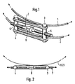
- a connecting device in the manner of a tensioning band is formed by two tensioning cables 1 and 2, which run at a parallel distance from one another.
- the endless tensioning cables 1 and 2 are wrapped around two connecting bolts 3 and 4, which lie parallel to the longitudinal axis of the cylindrical components, not shown, to be connected to one another.
- the connecting bolts 3 and 4 are each provided with centrally arranged and transverse threaded holes 5 and 6, in which a pressure clamping screw 7 engages, which lies symmetrically between the tensioning cables 1 and 2.
- the distance between the two connecting bolts 3 and 4 can be changed so far that in the two tension cables 1 and 2 the tension required to ensure a secure connection.
- the force distribution that occurs is indicated by arrows in FIG. 2.
- the simply drawn arrows symbolize tensile forces, while the double-drawn arrows symbolize the pressure forces exerted by the pressure clamping screw 7 on the connecting bolts 3 and 4.
- FIG. 3 is a second exemplary embodiment of a connecting device for cylindrical components.
- a one-piece tension belt 11 which is guided around a connection bolt 12, and a tension band consisting of two tension belts 13 and 14 overlap.
- the two straps 13 and 14 are guided around a second connecting pin 15.
- the two connecting bolts 12 and 15 are each provided with central transverse threaded bores 16 and 17, into which a pressure screw, not shown in the figure, can be inserted, analogously to the pressure screw 7 in FIG. 1.
- the compression tensioning screw also extends through a recess 18 in the one-piece tensioning belt 11.
- connection area of two components 21 and 22 to be connected in this area which are cylindrical in shape in this area.
- the two end areas of the two components are each provided with flanges or interface rings 23 and 24 which are conically shaped on one side.
- Each clamp element 25 has on its inside a conical recess 28 which is adapted to the shape of the flanges or interface rings 23 and 24.
- the clamp elements 25 which are arranged equidistantly over the circumference of the tensioning cables 26 and 27, are pressed against the connection point as a result of the tension present in these cables and thus press the two flanges or interface rings 23 and 24 against one another. Since the two tensioning cables 26 and 27 engage at a distance above or below the connection point, bending of the clamp elements 25 and thus gaping apart of the two flanges under the operating load are prevented.
- FIG. 5 differs from the one described above in that instead of the tension cables, two tension belts 31 and 32 are provided in this case, on which clamp elements 33 are held. In this case, too, two flanges or interface rings 35, 36, which are arranged on cylindrical components 37 and 38, are held together by the conical recess 34 of the clamp elements 33.
- Tension belts 31 and 32 shown in this figure correspond to tension belts 13 and 14 in FIG. 2.
- the tensioning strap device described above can be used for practically all diameters on interface rings or flanges. This also includes those with very large diameters, in which, due to the problems described, the use of such tension band connections was previously not considered possible and instead more complex and, above all, heavier connection devices were used.
- the required strengths the occurrence of any bending moments on the interface rings need not be taken into account when using the arrangement described above. Rather, the interface rings enclosed by the tensioning cables or tensioning straps form a system of high load-bearing capacity, which is essentially only limited by the strength of the interface rings or flanges.
- FIG. 3 is also particularly suitable for two or more tensioning elements, areas being able to alternate only with one tensioning strap and with two tensioning straps and clip elements are used, for example, only in the areas in which two tensioning straps are provided.
- the tension in the tensioning ropes or tensioning straps can be kept almost constant and the influence of friction can thus be minimized.
Landscapes
- Engineering & Computer Science (AREA)
- General Engineering & Computer Science (AREA)
- Mechanical Engineering (AREA)
- Remote Sensing (AREA)
- Aviation & Aerospace Engineering (AREA)
- Clamps And Clips (AREA)
Abstract
Bei einer Verbindungsvorrichtung für zylindrische Bauteile in Form eines Spannbandes, bei der das Spannband um zwei senkrecht zur Zugrichtung des Spannbandes angeordnete Bolzen (3,4) geführt ist, sind die miteinander zu verbindenden Bereiche des Spannbandes einander überlappend angeordnet, und die Bolzen werden über ein Druckspannelement (7) lösbar miteinander verbunden. Das Spannband kann dabei aus zwei Spannseilen (1,2) oder Spanngurten bestehen, die parallel zueinander ober- bzw. unterhalb des Druckspannelementes (7), vorzugsweise einer Druckspannschraube (7), angeordnet sind. Auf der Innenseite dieser Spannseile oder Spanngurte angeordnete Klammerelemente greifen formschlüssig über an den Bauteilen befindliche Flansche. 
Description
Die Erfindung betrifft eine Vorrichtung zum Verbinden zylindrischer Bauteile in Form eines zumindest teilweise aus zwei parallel verlaufenden Strängen bestehenden Spannbandes, das die zu verbindenden Bereiche der Bauteile umfaßt und das um senkrecht zur Zugrichtung des Spannbandes angeordnete Bolzen geführt ist, bei dem in der Schließstellung die miteinander zu verspannenden Bereiche des Bandes einander überlappend angeordnet und sich gegenüberliegende Bolzen über ein Druckspannelement lösbar miteinander verbunden sind.The invention relates to a device for connecting cylindrical components in the form of an at least partially consisting of two parallel strands of tension band, which comprises the areas of the components to be connected and which is guided around the bolt arranged perpendicular to the direction of tension of the tension band, in which in the closed position the one another areas of the band to be tensioned are arranged to overlap one another and opposing bolts are detachably connected to one another via a pressure tensioning element.
Vorrichtungen dieser Art werden häufig im Bereich der Raumfahrtechnik eingesetzt, um Nutzlasten an Endstufen von Trägerraketen zu haltern und beim Erreichen der vorgesehenen Zielumlaufbahnen durch Sprengen des Spannelementes davon zu lösen. Für diesen Verwendungszweck werden auch Vorrichtungen der eingangs genannten Art eingesetzt, die als Marman-Spannbandverbindung bezeichnet werden und bei denen auf der Innenseite des Spannbandes eine Anzahl von Klammerelementen angeordnet ist. Solche Klammerelemente weisen auf ihrer Innenseite konische Ausnehmungen auf und greifen mit diesen über entsprechend geformte Flansche oder Interfaceringe, welche an den zu verbindenden Endbereichen der einzelnen Bauteile angeordnet sind. Beim Sprengen solcher Spannelemente, das im Fall des sog. Marman-Spannbandes aus einer Zugspannschraube besteht, werden diese Klammerelemente von den Flanschen oder Interfaceringen gezogen, so daß sich die Bauteile voneinander, beispielsweise eine Nutzlast von einer Trägerendstufe, lösen.Devices of this type are frequently used in the field of space technology to hold payloads on the final stages of launchers and to release them when the intended orbits are reached by detonating the tensioning element. Devices of the type mentioned at the outset are also used for this purpose, which are referred to as Marman tension band connections and in which a number of clamp elements are arranged on the inside of the tension band. Such clamp elements have conical recesses on their inside and engage with them via appropriately shaped flanges or interface rings which are arranged on the end regions of the individual components to be connected. When such tensioning elements are blown, which in the case of the so-called Marman tensioning band consists of a tension screw, these clamping elements are pulled from the flanges or interface rings, so that the components separate from one another, for example a payload from a carrier output stage.
Aufgabe der Erfindung ist es, eine Vorrichtung der eingangs genannten Art so auszubilden, daß diese bei möglichst geringem Eigengewicht eine hohe Tragfähigkeit aufweist, und daß sie für einen möglichst weiten Bereich von Bauteildurchmessern einsetzbar wird.The object of the invention is to design a device of the type mentioned in such a way that it is as small as possible Dead weight has a high load-bearing capacity and that it can be used for the widest possible range of component diameters.
Die Erfindung löst die Aufgabe, indem sie vorsieht, daß auf der Innenseite des Spannbandes Klammerelemente vorgesehen sind, die mit Ausnehmungen versehen sind, welche formschlüssig über flanschartige, umfangsseitig angeordnete Ansätze der Bauteile greifen und daß die Klammerelemente in denjenigen Bereichen des Spannbandes angeordnet sind, die geteilt ausgebildet sind.The invention solves the problem by providing that clip elements are provided on the inside of the tension band, which are provided with recesses which engage positively over flange-like, peripherally arranged approaches of the components and that the clip elements are arranged in those areas of the tension band that are divided.
Durch diese Maßnahme wird erreicht, daß über den gesamten Umfangsbereich der zu verbindenden Bauteile ein gleichmäßiger Abstand zwischen Spannband und Interfaceringen bzw. Flanschen besteht. Ein Auftreten von Biegebeanspruchungen an den Interfaceringen bzw. den Flanschen, wie das beispielsweise bei der Verwendung von Zugspannschrauben zum Verbinden der Spannbandenden auftreten kann, wird dadurch vermieden, daß die neutrale Faser des Spannbandes im Bereich der Spannschraube und der von diesen zusammengehaltenen Bolzen einen größeren Abstand von den Interfaceringen als in allen anderen Bereichen aufweist. Die in diesen Bereichen konzentrierten Querkräfte und die dadurch bewirkten Biegespannungen in den Interfaceringen bzw. Flanschen würden die Belastbarkeit einer derartigen Vorrichtung erheblich vermindern. Indem bei der erfindungsmäßigen Vorrichtung das Auftreten solcher Zusatzbeanspruchungen von vornherein ausgeschlossen wird, ist es möglich, die Belastbarkeit des gesamten Systems drastisch zu erhöhen.This measure ensures that there is a uniform distance between the clamping band and the interface rings or flanges over the entire circumferential area of the components to be connected. An occurrence of bending stresses on the interface rings or the flanges, as can occur, for example, when using tension screws to connect the ends of the tensioning straps, is avoided by the neutral fiber of the tensioning strap being in the area of the tensioning screw and the bolts held together by a greater distance of the interface rings than in all other areas. The transverse forces concentrated in these areas and the resulting bending stresses in the interface rings or flanges would considerably reduce the load capacity of such a device. By excluding the occurrence of such additional stresses from the outset in the device according to the invention, it is possible to drastically increase the resilience of the entire system.
Durch die weitere Ausgestaltung der erfindungsgemäßen Vorrichtung kann die vorgesehene Verwendung zweier symmetrisch zum Druckspannelement angeordneter Spanngurte bzw. Spannseile und zwar durch Verteilung der auftretenden Kräfte noch weiter optimiert werden. Diese Maßnahme ist insbesondere in Verbindung mit dem Einsatz der erwähnten Klammerelemente von Vorteil, da durch sie ein Aufbiegen der gesamten Verbindung zuverlässig unterbunden wird. Hierdurch werden die von der erfindungsmäßigen Vorrichtung tolerierten Betriebslasten nochmals heraufgesetzt und ihr Einsatz auch bei sehr großen Bauteildurchmessern ermöglicht. Ferner ergibt sich durch diese Maßnahme eine zusätzliche Gewichtseinsparung.Through the further configuration of the device according to the invention, the intended use of two tensioning belts or tensioning ropes arranged symmetrically to the compression tensioning element can be further optimized by distributing the occurring forces. This measure is particularly in connection with the use of the mentioned clamp elements is advantageous because it reliably prevents bending of the entire connection. As a result, the operating loads tolerated by the device according to the invention are increased again and their use is made possible even with very large component diameters. This measure also results in additional weight savings.
Im Folgenden soll die Erfindung anhand von in der Zeichnung dargestellten Ausführungsbeispielen näher erläutert werden. Es zeigen:
- Fig. 1 den Verschlußbereich eines ersten Spannbandes,
- Fig. 2 in einer Prinzipskizze die Kräfteverteilung bei einer Anordnung gemäß Fig. 1,
- Fig. 3 den Verschlußbereich eines zweiten spannbandes und
- Fig. 4 und Fig. 5 je einen Schnitt durch den Verbindungsbereich zweier Bauteile.
- 1 shows the closure area of a first strap,
- 2 is a schematic diagram of the distribution of forces in an arrangement according to FIG. 1,
- Fig. 3 shows the closure area of a second strap and
- FIGS. 4 and 5 each show a section through the connection area of two components.
In den Figuren sind gleiche Bauteile mit den gleichen Bezugszeichen versehen.In the figures, the same components are provided with the same reference symbols.
Bei der in Fig. 1 dargestellten Anordnung wird eine Verbindungsvorrichtung nach Art eines Spannbandes von zwei Spannseilen 1 und 2 gebildet, die mit parallelem Abstand zueinander verlaufen. Die endlosen Spannseile 1 und 2 sind um zwei Verbindungsbolzen 3 und 4 geschlungen, die parallel zur Längsachse der miteinander zu verbindenden hier nicht dargestellten zylindrischen Bauteile liegen.In the arrangement shown in FIG. 1, a connecting device in the manner of a tensioning band is formed by two
Die Verbindungsbolzen 3 und 4 sind jeweils mit mittig angeordneten und quer verlaufenden Gewindebohrungen 5 und 6 versehen, in die eine Druckspannschraube 7 greift, die symmetrisch zwischen den Spannseilen 1 und 2 liegt.The connecting
Über die Druckspannschraube 7, die in ihrem beiden Endbereichen mit gegenläufigen Gewinden versehen ist und die in der Mitte eine feststehend angeordnete oder am Ende lösbare Einstellmutter 8 aufweist, ist der Abstand der beiden Verbindungsbolzen 3 und 4 so weit veränderbar, daß in den beiden Spannseilen 1 und 2 die für die Gewährleistung einer sicheren Verbindung erforderliche Zugspannung herrscht. Die dabei auftretende Kräfteverteilung ist anhand von Pfeilen in Fig. 2 gekennzeichnet. Die einfach gezeichneten Pfeile symbolisieren dabei Zugkräfte, während die doppelt gezeichneten Pfeile die von der Druckspannschraube 7 auf die Verbindungsbolzen 3 und 4 ausgeübten Druckkräfte symbolisieren.About the
Bei der in Fig. 3 dargestellten Anordnung handelt es sich um ein zweites Ausführungsbeispiel einer Verbindungsvorrichtung für zylindrische Bauteile. In dem in dieser Figur dargestellten Verbindungsbereich überlappen sich ein einteiliger Spanngurt 11, der um einen Verbindungsbolzen 12 geführt ist und ein aus zwei Spanngurten 13 und 14 bestehendes Spannband. Die beiden Spanngurte 13 und 14 sind dabei um einen zweiten Verbindungsbolzen 15 geführt. Auch bei diesem Ausführungsbeispiel sind die beiden Verbindungsbolzen 12 und 15 jeweils mit mittigen Quergewindebohrungen 16 und 17 versehen, in die eine in der Figur nicht dargestellte Durckspannschraube analog zur Druckspannschraube 7 in Fig. 1 einsetzbar ist. Die Druckspannschraube erstreckt sich dabei auch durch eine Aussparung 18 des einteiligen Spanngurtes 11.The arrangement shown in FIG. 3 is a second exemplary embodiment of a connecting device for cylindrical components. In the connection area shown in this figure, a one-piece tension belt 11, which is guided around a
Auch bei dieser Anordnung wird über die Druckspannschraube die für die Aufrechterhaltung der Verbindung der beiden Bauteile erforder liche Zugspannung in den Gurten 11 bzw. 13 und 14 erzeugt.In this arrangement, too, the pressure clamping screw is required to maintain the connection of the two components Liche tension in the
Fig. 4 zeigt in einer Schnittdarstellung den Verbindungsbereich zweier miteinander zu verbindender, in diesem Bereich zylindrisch ausgebildeter Bauteile 21 und 22. Die beiden Bauteile sind dabei in ihren Endbereichen jeweils mit einseitig konisch geformten Flanschen oder Interfaceringe 23 bzw. 24 versehen. Über diese greifen Klammerelemente 25, von denen eines in der Figur dargestellt ist und die an Spannseilen 26 und 27 gehaltert sind. Letztere entsprechen den Spannseilen 1 und 2 in Fig. 1.4 shows a sectional view of the connection area of two
Jedes Klammerelement 25 weist auf seiner Innenseite eine konische Ausnehmung 28 auf, die der Form der Flansche oder Interfaceringe 23 und 24 angepaßt ist.Each
In der Schließstellung der Vorrichtung werden die Klammerelemente 25, die äquidistant über den Umfang der Spannseile 26 und 27 verteilt angeordnet sind, infolge der in diesen Seilen herrschenden Zugspannung gegen die Verbindungsstelle gedrückt und pressen somit die beiden Flansche oder Interfaceringe 23 und 24 aufeinander. Da die beiden Spannseile 26 und 27 dabei in einem Abstand ober- bzw. unterhalb der Verbindungsstelle angreifen, wird ein Aufbiegen der Klammerelemente 25 und damit ein Auseinanderklaffen der beiden Flansche unter der Betriebslast verhindert.In the closed position of the device, the
Die in Fig. 5 dargestellte Anordnung schließlich unterscheidet sich von der vorherstehend beschriebenen dahingehend, daß anstelle der Spannseile in diesem Fall zwei Spanngurte 31 und 32 vorgesehen sind, an denen Klammerelemente 33 gehaltert sind. Auch in diesem Fall werden durch die konische Ausnehmung 34 der Klammerelemente 33 zwei Flansche bzw. Interfaceringe 35, 36, die an zylindrischen Bauteilen 37 und 38 angeordnet sind, zusammengehalten. Die in dieser Figur dargestellten Spanngurte 31 und 32 entsprechen dabei den Spanngurten 13 und 14 in Fig. 2.Finally, the arrangement shown in FIG. 5 differs from the one described above in that instead of the tension cables, two
Durch die Wahl entsprechend langer Spanngurte bzw. Spannseile und die Anordnung der erforderlichen Anzahl von Klammerelementen kann die vorstehend beschriebene Spannbandvorrichtung für praktisch alle Durchmesser an Interfaceringen bzw. Flanschen eingesetzt werden. Darunter auch für solche mit sehr großen Durchmessern, bei denen bisher aufgrund der beschriebenen Probleme ein Einsatz derartiger Spannbandverbindungen als nicht möglich angesehen wurde und stattdessen aufwendigere und vor allem schwerere Verbindungsvorrichtungen eingesetzt wurden. Bei der Auslegung der erforderlichen Festigkeiten braucht bei Verwendung der vorstehend beschriebenen Anordnung das Auftreten von etwaigen Biegemomenten an den Interfaceringen nicht berücksichtigt zu werden. Vielmehr bilden die von den Spannseilen bzw. Spannbändern umschlossenen Interfaceringe ein System hoher Tragfähigkeit, die im wesentlichen nur durch die Festigkeit der Interfaceringe oder Flansche begrenzt wird.By choosing suitably long tensioning straps or tensioning ropes and the arrangement of the required number of clamp elements, the tensioning strap device described above can be used for practically all diameters on interface rings or flanges. This also includes those with very large diameters, in which, due to the problems described, the use of such tension band connections was previously not considered possible and instead more complex and, above all, heavier connection devices were used. When designing the required strengths, the occurrence of any bending moments on the interface rings need not be taken into account when using the arrangement described above. Rather, the interface rings enclosed by the tensioning cables or tensioning straps form a system of high load-bearing capacity, which is essentially only limited by the strength of the interface rings or flanges.
Anzumerken ist, daß es im Rahmen der Erfindung dabei sowohl möglich ist, auf den gesamten Umfang lediglich eine oder mehrere aus den Verbindungsbolzen und der Druckspannschraube bestehende Schließvorrichtung anzuordnen, so daß beispielsweise zwei endlose Spannseile geeigneter Abmessung verwendet werden können. Für zwei oder mehrere Spannelemente eignet sich insbesondere auch die in Fig. 3 beschriebene Anordnung, wobei sich Bereiche nur mit einem Spanngurt und mit zwei Spanngurten abwechseln können und Klammerelemente beispielsweise nur in den Bereichen eingesetzt sind, in denen zwei Spanngurte vorgesehen sind.It should be noted that it is possible within the scope of the invention to arrange only one or more locking devices consisting of the connecting bolts and the compression screw on the entire circumference, so that, for example, two endless tension cables of suitable dimensions can be used. The arrangement described in FIG. 3 is also particularly suitable for two or more tensioning elements, areas being able to alternate only with one tensioning strap and with two tensioning straps and clip elements are used, for example, only in the areas in which two tensioning straps are provided.
Durch die größere Anzahl der Spannelemente kann die Zugspannung in den Spannseilen oder Spanngurten annähernd konstant gehalten und der Reibungseinfluß somit minimiert werden.Due to the larger number of tensioning elements, the tension in the tensioning ropes or tensioning straps can be kept almost constant and the influence of friction can thus be minimized.
- 1, 2 Spannseile1, 2 tension cables
- 3, 4 Verbindungsbolzen3, 4 connecting bolts
- 5, 6 Gewindebohrungen5, 6 threaded holes
- 7 Einstellmutter7 adjusting nut
- 11, 13, 14 Spanngurte11, 13, 14 tension belts
- 12, 15 Verbindungsbolzen12, 15 connecting bolts
- 16, 17 Gewindebohrungen16, 17 threaded holes
- 18 Aussparung18 recess
- 21, 22 Bauteile21, 22 components
- 23, 24 Flansche23, 24 flanges
- 26, 27 Klammerelement26, 27 bracket element
- 28 Ausnehmung28 recess
- 31, 32 Spanngurte31, 32 straps
- 33 Klammerelement33 clip element
- 34 Ausnehmung34 recess
- 35, 36 Flansche35, 36 flanges
- 37, 38 Bauteile37, 38 components
Claims (6)
Applications Claiming Priority (2)
| Application Number | Priority Date | Filing Date | Title |
|---|---|---|---|
| DE3727448 | 1987-08-18 | ||
| DE3727448A DE3727448C2 (en) | 1987-08-18 | 1987-08-18 | Device for connecting cylindrical components |
Publications (3)
| Publication Number | Publication Date |
|---|---|
| EP0303902A2 true EP0303902A2 (en) | 1989-02-22 |
| EP0303902A3 EP0303902A3 (en) | 1989-10-18 |
| EP0303902B1 EP0303902B1 (en) | 1992-07-22 |
Family
ID=6333946
Family Applications (1)
| Application Number | Title | Priority Date | Filing Date |
|---|---|---|---|
| EP88112687A Expired - Lifetime EP0303902B1 (en) | 1987-08-18 | 1988-08-04 | Device for connecting cylindrical elements |
Country Status (4)
| Country | Link |
|---|---|
| US (1) | US5157816A (en) |
| EP (1) | EP0303902B1 (en) |
| JP (1) | JP2532923B2 (en) |
| DE (1) | DE3727448C2 (en) |
Cited By (4)
| Publication number | Priority date | Publication date | Assignee | Title |
|---|---|---|---|---|
| WO1994010513A1 (en) * | 1992-10-27 | 1994-05-11 | Level Energietechniek B.V. | Apparatus for receiving sun radiation and method for preparing such an apparatus |
| NL9300120A (en) * | 1993-01-21 | 1994-08-16 | Woerd Bv | Device for attaching an object to a tube, in particular for attaching an object to the handlebars of a bicycle |
| WO2004072490A3 (en) * | 2003-02-11 | 2004-09-23 | J S Tec | Positionable anchoring device on a long support of any section |
| WO2013156830A1 (en) * | 2012-04-20 | 2013-10-24 | Straub Werke Ag | Clamping belt and pipe coupling for the force-closed connection of pipes, in particular of smooth-end pipes |
Families Citing this family (17)
| Publication number | Priority date | Publication date | Assignee | Title |
|---|---|---|---|---|
| US5809623A (en) * | 1997-08-06 | 1998-09-22 | Delaware Capital Formation, Inc. | Squeeze clamp |
| DE10033093B4 (en) * | 2000-07-07 | 2005-03-03 | Eads Space Transportation Gmbh | Device for releasably connecting rotational-system-metric components |
| DE10301783B4 (en) * | 2003-01-18 | 2005-04-28 | Eads Space Transp Gmbh | Device for releasably connecting rotationally symmetrical components |
| US7056073B2 (en) * | 2003-03-12 | 2006-06-06 | Ardo Louis D | Load securing device and method for using the same |
| SG125980A1 (en) * | 2005-03-15 | 2006-10-30 | Goh Peng Chew | Fastening mechanism |
| CA2625212C (en) * | 2005-10-06 | 2012-12-04 | Eads Casa Espacio S.L. | Apparatus for connecting/separating a launch vehicle and a satellite |
| FR2974566B1 (en) * | 2011-04-26 | 2013-12-27 | Astrium Sas | METHOD FOR TEMPORARILY CONNECTING TWO PARTS, SUCH AS TWO STAGES OF A SPATIAL LAUNCHER, AND A SET OF TWO TEMPORARYLY CONNECTED PIECES |
| BR112015032446A2 (en) * | 2013-07-02 | 2017-07-25 | Mra Systems Inc | turbocharger engine, turbocharger and ribbon clamp |
| CA2868597C (en) * | 2014-10-21 | 2020-09-29 | Wellsite Guard Ltd. | Rainguard for oilwell stuffing box containment basin |
| GB2541980B (en) * | 2015-09-02 | 2018-02-07 | Romax Tech Limited | Bearing compression strap |
| SE540399C2 (en) * | 2016-04-20 | 2018-09-11 | Bae Systems Bofors Ab | Support device for divisible parachute grenade |
| US10514119B2 (en) * | 2016-11-22 | 2019-12-24 | Schauenburg Flexadux Corporation | Duct coupling system |
| CN108050351B (en) * | 2017-12-08 | 2020-01-10 | 中国科学院长春光学精密机械与物理研究所 | Unlocking type space remote sensing camera support |
| FR3096033B1 (en) * | 2019-05-14 | 2021-05-28 | Spirit Tech | Circumferential coupling system, in particular for coupling a satellite and a planet carrier |
| CN111114853B (en) * | 2019-12-24 | 2021-04-20 | 兰州空间技术物理研究所 | Active heat conduction docking locking interface device for spacecraft |
| CN111056052B (en) * | 2019-12-31 | 2021-04-20 | 中国科学院空间应用工程与技术中心 | An on-orbit load module repetitive locking and releasing mechanism |
| JP7530570B2 (en) * | 2020-11-20 | 2024-08-08 | 中国電力株式会社 | Pole mounting band |
Family Cites Families (21)
| Publication number | Priority date | Publication date | Assignee | Title |
|---|---|---|---|---|
| US3104898A (en) * | 1963-09-24 | Tube couplers | ||
| GB591284A (en) * | 1945-02-02 | 1947-08-13 | William Wilson Hamill | Means for clamping together two adjacent members |
| US1432572A (en) * | 1921-06-22 | 1922-10-17 | Henry A Schroeder | Hose clamp |
| US1468297A (en) * | 1923-01-05 | 1923-09-18 | Hogg John Steadman | Clip for pipes or tubes |
| GB454009A (en) * | 1935-01-17 | 1936-09-17 | Marcel Urbain Caillau | Hose clamp |
| GB573695A (en) * | 1943-08-17 | 1945-12-03 | Robert Cuthbert Scott Jamie | Improvements in or relating to metal hose clips |
| US2561635A (en) * | 1948-08-02 | 1951-07-24 | Carroll W Prochaska | Hose clamp |
| BE511690A (en) * | 1951-05-28 | |||
| US3029095A (en) * | 1955-08-18 | 1962-04-10 | Garrett Corp | Flange connecting clamp |
| GB885996A (en) * | 1958-09-23 | 1962-01-03 | Kac Ltd | Improvements relating to pipe, hose and like couplings |
| US3359018A (en) * | 1965-06-24 | 1967-12-19 | Sta Rite Industries | Pipe coupling |
| FR1543373A (en) * | 1967-09-08 | 1968-10-25 | Hose clamp | |
| CH534311A (en) * | 1971-02-25 | 1973-02-28 | Von Roll Ag | Bride |
| GB1393555A (en) * | 1972-12-13 | 1975-05-07 | Canning Brett Ltd | Band clips for hoses and pipes |
| US3861723A (en) * | 1973-08-28 | 1975-01-21 | Us Air Force | V-band coupling |
| JPS5316200A (en) * | 1976-07-30 | 1978-02-14 | Hitachi Ltd | Core water purifying device for boiling water type reactor |
| JPS5334400A (en) * | 1976-10-25 | 1978-03-30 | Naka Tech Lab | Escaping device for building |
| DE2655772C3 (en) * | 1976-12-09 | 1980-07-31 | Messerschmitt-Boelkow-Blohm Gmbh, 8000 Muenchen | Tension band with movable tensioning blocks |
| US4527818A (en) * | 1981-02-17 | 1985-07-09 | Texaco Inc. | Coupling for pipe or tubing |
| US4489464A (en) * | 1982-07-07 | 1984-12-25 | Renzo Massari | U-Profiled improved hose clamp |
| JPS61287900A (en) * | 1985-06-15 | 1986-12-18 | 日産自動車株式会社 | Mounting structure of auxiliary booster |
-
1987
- 1987-08-18 DE DE3727448A patent/DE3727448C2/en not_active Expired - Fee Related
-
1988
- 1988-08-04 EP EP88112687A patent/EP0303902B1/en not_active Expired - Lifetime
- 1988-08-12 JP JP63200325A patent/JP2532923B2/en not_active Expired - Fee Related
-
1990
- 1990-07-09 US US07/549,535 patent/US5157816A/en not_active Expired - Lifetime
Cited By (7)
| Publication number | Priority date | Publication date | Assignee | Title |
|---|---|---|---|---|
| WO1994010513A1 (en) * | 1992-10-27 | 1994-05-11 | Level Energietechniek B.V. | Apparatus for receiving sun radiation and method for preparing such an apparatus |
| NL9300120A (en) * | 1993-01-21 | 1994-08-16 | Woerd Bv | Device for attaching an object to a tube, in particular for attaching an object to the handlebars of a bicycle |
| WO2004072490A3 (en) * | 2003-02-11 | 2004-09-23 | J S Tec | Positionable anchoring device on a long support of any section |
| WO2013156830A1 (en) * | 2012-04-20 | 2013-10-24 | Straub Werke Ag | Clamping belt and pipe coupling for the force-closed connection of pipes, in particular of smooth-end pipes |
| CN104160196A (en) * | 2012-04-20 | 2014-11-19 | 瑞士斯特劳勃管道接头有限公司 | Clamping belt and pipe coupling for the force-closed connection of pipes, in particular of smooth-end pipes |
| CN104160196B (en) * | 2012-04-20 | 2016-05-11 | 瑞士斯特劳勃管道接头有限公司 | Fit belt and the joint for pipe for force closure ground tube connector, particularly plain-end tube |
| US9631748B2 (en) | 2012-04-20 | 2017-04-25 | Straub Werke Ag | Clamping belt and pipe coupling for the force-closed connection of pipes, in particular of smooth-end pipes |
Also Published As
| Publication number | Publication date |
|---|---|
| JPS6483499A (en) | 1989-03-29 |
| US5157816A (en) | 1992-10-27 |
| EP0303902A3 (en) | 1989-10-18 |
| EP0303902B1 (en) | 1992-07-22 |
| DE3727448C2 (en) | 1994-10-13 |
| JP2532923B2 (en) | 1996-09-11 |
| DE3727448A1 (en) | 1989-03-02 |
Similar Documents
| Publication | Publication Date | Title |
|---|---|---|
| EP0303902A2 (en) | Device for connecting cylindrical elements | |
| DE29605115U1 (en) | Belt retractor | |
| EP1170539B1 (en) | Device for releasably connecting elements with rotational symmetry | |
| DE2440587B2 (en) | ANCHORING DEVICE FOR STRENGTHENED CONCRETE COMPONENTS | |
| EP0145646A2 (en) | Device for fixing belts to members, tensioning and/or checking devices | |
| DE2114006C3 (en) | Reinforcement insert for belts or belts, in particular conveyor belts | |
| DE3640695A1 (en) | DEVICE FOR FIXING FIBER-SHAPED RELIEF RELEASE LAYERS, IN PARTICULAR WITH LIGHT-WAVE LEAD CABLES | |
| DE3725036C2 (en) | ||
| AT391916B (en) | BOOM WITH HORIZONTAL ROPE TENSIONING | |
| EP4199212A1 (en) | Battery assembly comprising battery modules and tightening straps, motor vehicle comprising battery assembly | |
| DE3623399C1 (en) | Totally insulated anchor clamp (tension clamp, dead-end clamp) | |
| DE2646998A1 (en) | BELT FORCE LIMITERS FOR VEHICLE SAFETY BELTS | |
| DE3539392C2 (en) | ||
| WO2021032351A1 (en) | Device and method for bracing a fuel cell stack | |
| DE102020108930A1 (en) | Detachable rope end connection for highly modular fiber ropes | |
| DE3638179C2 (en) | Detachable connection for the chair of a paper machine | |
| DE2440587C2 (en) | Anchoring device for prestressed concrete components | |
| AT3805U1 (en) | DAMPING DEVICE FOR A CABLE CAR | |
| DE9300483U1 (en) | End connection for a wire rope | |
| DE202024102227U1 (en) | Spiral cable with fixed cable windings | |
| DE3423382A1 (en) | Arresting apparatus for a safety belt | |
| DE102008018094A1 (en) | Vibration damping arrangement e.g. for aeronautics electronics, and transport, | |
| DE102021205907A1 (en) | connection | |
| DE29804260U1 (en) | Deflection fitting for a seat belt | |
| DE102021131273A1 (en) | Chain link of a cable routing device with strain relief |
Legal Events
| Date | Code | Title | Description |
|---|---|---|---|
| PUAI | Public reference made under article 153(3) epc to a published international application that has entered the european phase |
Free format text: ORIGINAL CODE: 0009012 |
|
| AK | Designated contracting states |
Kind code of ref document: A2 Designated state(s): FR GB IT NL |
|
| 17P | Request for examination filed |
Effective date: 19890622 |
|
| PUAL | Search report despatched |
Free format text: ORIGINAL CODE: 0009013 |
|
| AK | Designated contracting states |
Kind code of ref document: A3 Designated state(s): FR GB IT NL |
|
| 17Q | First examination report despatched |
Effective date: 19901205 |
|
| GRAA | (expected) grant |
Free format text: ORIGINAL CODE: 0009210 |
|
| AK | Designated contracting states |
Kind code of ref document: B1 Designated state(s): FR GB IT NL |
|
| ET | Fr: translation filed | ||
| ITF | It: translation for a ep patent filed | ||
| GBT | Gb: translation of ep patent filed (gb section 77(6)(a)/1977) | ||
| PLBE | No opposition filed within time limit |
Free format text: ORIGINAL CODE: 0009261 |
|
| STAA | Information on the status of an ep patent application or granted ep patent |
Free format text: STATUS: NO OPPOSITION FILED WITHIN TIME LIMIT |
|
| 26N | No opposition filed | ||
| REG | Reference to a national code |
Ref country code: GB Ref legal event code: IF02 |
|
| PGFP | Annual fee paid to national office [announced via postgrant information from national office to epo] |
Ref country code: GB Payment date: 20040712 Year of fee payment: 17 |
|
| PGFP | Annual fee paid to national office [announced via postgrant information from national office to epo] |
Ref country code: FR Payment date: 20040830 Year of fee payment: 17 |
|
| PGFP | Annual fee paid to national office [announced via postgrant information from national office to epo] |
Ref country code: NL Payment date: 20040831 Year of fee payment: 17 |
|
| PG25 | Lapsed in a contracting state [announced via postgrant information from national office to epo] |
Ref country code: IT Free format text: LAPSE BECAUSE OF NON-PAYMENT OF DUE FEES;WARNING: LAPSES OF ITALIAN PATENTS WITH EFFECTIVE DATE BEFORE 2007 MAY HAVE OCCURRED AT ANY TIME BEFORE 2007. THE CORRECT EFFECTIVE DATE MAY BE DIFFERENT FROM THE ONE RECORDED. Effective date: 20050804 Ref country code: GB Free format text: LAPSE BECAUSE OF NON-PAYMENT OF DUE FEES Effective date: 20050804 |
|
| PG25 | Lapsed in a contracting state [announced via postgrant information from national office to epo] |
Ref country code: NL Free format text: LAPSE BECAUSE OF NON-PAYMENT OF DUE FEES Effective date: 20060301 |
|
| GBPC | Gb: european patent ceased through non-payment of renewal fee |
Effective date: 20050804 |
|
| PG25 | Lapsed in a contracting state [announced via postgrant information from national office to epo] |
Ref country code: FR Free format text: LAPSE BECAUSE OF NON-PAYMENT OF DUE FEES Effective date: 20060428 |
|
| NLV4 | Nl: lapsed or anulled due to non-payment of the annual fee |
Effective date: 20060301 |
|
| REG | Reference to a national code |
Ref country code: FR Ref legal event code: ST Effective date: 20060428 |