EP0303224A2 - Dispositif de cristallisation - Google Patents
Dispositif de cristallisation Download PDFInfo
- Publication number
- EP0303224A2 EP0303224A2 EP88112911A EP88112911A EP0303224A2 EP 0303224 A2 EP0303224 A2 EP 0303224A2 EP 88112911 A EP88112911 A EP 88112911A EP 88112911 A EP88112911 A EP 88112911A EP 0303224 A2 EP0303224 A2 EP 0303224A2
- Authority
- EP
- European Patent Office
- Prior art keywords
- clamping
- hose
- crystallization
- elastic
- hoses
- Prior art date
- Legal status (The legal status is an assumption and is not a legal conclusion. Google has not performed a legal analysis and makes no representation as to the accuracy of the status listed.)
- Withdrawn
Links
Images


Classifications
-
- C—CHEMISTRY; METALLURGY
- C30—CRYSTAL GROWTH
- C30B—SINGLE-CRYSTAL GROWTH; UNIDIRECTIONAL SOLIDIFICATION OF EUTECTIC MATERIAL OR UNIDIRECTIONAL DEMIXING OF EUTECTOID MATERIAL; REFINING BY ZONE-MELTING OF MATERIAL; PRODUCTION OF A HOMOGENEOUS POLYCRYSTALLINE MATERIAL WITH DEFINED STRUCTURE; SINGLE CRYSTALS OR HOMOGENEOUS POLYCRYSTALLINE MATERIAL WITH DEFINED STRUCTURE; AFTER-TREATMENT OF SINGLE CRYSTALS OR A HOMOGENEOUS POLYCRYSTALLINE MATERIAL WITH DEFINED STRUCTURE; APPARATUS THEREFOR
- C30B7/00—Single-crystal growth from solutions using solvents which are liquid at normal temperature, e.g. aqueous solutions
- C30B7/14—Single-crystal growth from solutions using solvents which are liquid at normal temperature, e.g. aqueous solutions the crystallising materials being formed by chemical reactions in the solution
-
- B—PERFORMING OPERATIONS; TRANSPORTING
- B01—PHYSICAL OR CHEMICAL PROCESSES OR APPARATUS IN GENERAL
- B01D—SEPARATION
- B01D9/00—Crystallisation
-
- B—PERFORMING OPERATIONS; TRANSPORTING
- B01—PHYSICAL OR CHEMICAL PROCESSES OR APPARATUS IN GENERAL
- B01L—CHEMICAL OR PHYSICAL LABORATORY APPARATUS FOR GENERAL USE
- B01L3/00—Containers or dishes for laboratory use, e.g. laboratory glassware; Droppers
- B01L3/06—Crystallising dishes
-
- C—CHEMISTRY; METALLURGY
- C30—CRYSTAL GROWTH
- C30B—SINGLE-CRYSTAL GROWTH; UNIDIRECTIONAL SOLIDIFICATION OF EUTECTIC MATERIAL OR UNIDIRECTIONAL DEMIXING OF EUTECTOID MATERIAL; REFINING BY ZONE-MELTING OF MATERIAL; PRODUCTION OF A HOMOGENEOUS POLYCRYSTALLINE MATERIAL WITH DEFINED STRUCTURE; SINGLE CRYSTALS OR HOMOGENEOUS POLYCRYSTALLINE MATERIAL WITH DEFINED STRUCTURE; AFTER-TREATMENT OF SINGLE CRYSTALS OR A HOMOGENEOUS POLYCRYSTALLINE MATERIAL WITH DEFINED STRUCTURE; APPARATUS THEREFOR
- C30B29/00—Single crystals or homogeneous polycrystalline material with defined structure characterised by the material or by their shape
- C30B29/54—Organic compounds
- C30B29/58—Macromolecular compounds
-
- C—CHEMISTRY; METALLURGY
- C30—CRYSTAL GROWTH
- C30B—SINGLE-CRYSTAL GROWTH; UNIDIRECTIONAL SOLIDIFICATION OF EUTECTIC MATERIAL OR UNIDIRECTIONAL DEMIXING OF EUTECTOID MATERIAL; REFINING BY ZONE-MELTING OF MATERIAL; PRODUCTION OF A HOMOGENEOUS POLYCRYSTALLINE MATERIAL WITH DEFINED STRUCTURE; SINGLE CRYSTALS OR HOMOGENEOUS POLYCRYSTALLINE MATERIAL WITH DEFINED STRUCTURE; AFTER-TREATMENT OF SINGLE CRYSTALS OR A HOMOGENEOUS POLYCRYSTALLINE MATERIAL WITH DEFINED STRUCTURE; APPARATUS THEREFOR
- C30B35/00—Apparatus not otherwise provided for, specially adapted for the growth, production or after-treatment of single crystals or of a homogeneous polycrystalline material with defined structure
- C30B35/002—Crucibles or containers
-
- C—CHEMISTRY; METALLURGY
- C30—CRYSTAL GROWTH
- C30B—SINGLE-CRYSTAL GROWTH; UNIDIRECTIONAL SOLIDIFICATION OF EUTECTIC MATERIAL OR UNIDIRECTIONAL DEMIXING OF EUTECTOID MATERIAL; REFINING BY ZONE-MELTING OF MATERIAL; PRODUCTION OF A HOMOGENEOUS POLYCRYSTALLINE MATERIAL WITH DEFINED STRUCTURE; SINGLE CRYSTALS OR HOMOGENEOUS POLYCRYSTALLINE MATERIAL WITH DEFINED STRUCTURE; AFTER-TREATMENT OF SINGLE CRYSTALS OR A HOMOGENEOUS POLYCRYSTALLINE MATERIAL WITH DEFINED STRUCTURE; APPARATUS THEREFOR
- C30B7/00—Single-crystal growth from solutions using solvents which are liquid at normal temperature, e.g. aqueous solutions
-
- Y—GENERAL TAGGING OF NEW TECHNOLOGICAL DEVELOPMENTS; GENERAL TAGGING OF CROSS-SECTIONAL TECHNOLOGIES SPANNING OVER SEVERAL SECTIONS OF THE IPC; TECHNICAL SUBJECTS COVERED BY FORMER USPC CROSS-REFERENCE ART COLLECTIONS [XRACs] AND DIGESTS
- Y10—TECHNICAL SUBJECTS COVERED BY FORMER USPC
- Y10S—TECHNICAL SUBJECTS COVERED BY FORMER USPC CROSS-REFERENCE ART COLLECTIONS [XRACs] AND DIGESTS
- Y10S117/00—Single-crystal, oriented-crystal, and epitaxy growth processes; non-coating apparatus therefor
- Y10S117/901—Levitation, reduced gravity, microgravity, space
-
- Y—GENERAL TAGGING OF NEW TECHNOLOGICAL DEVELOPMENTS; GENERAL TAGGING OF CROSS-SECTIONAL TECHNOLOGIES SPANNING OVER SEVERAL SECTIONS OF THE IPC; TECHNICAL SUBJECTS COVERED BY FORMER USPC CROSS-REFERENCE ART COLLECTIONS [XRACs] AND DIGESTS
- Y10—TECHNICAL SUBJECTS COVERED BY FORMER USPC
- Y10T—TECHNICAL SUBJECTS COVERED BY FORMER US CLASSIFICATION
- Y10T117/00—Single-crystal, oriented-crystal, and epitaxy growth processes; non-coating apparatus therefor
- Y10T117/10—Apparatus
- Y10T117/1024—Apparatus for crystallization from liquid or supercritical state
- Y10T117/1092—Shape defined by a solid member other than seed or product [e.g., Bridgman-Stockbarger]
Definitions
- the invention relates to a crystallization device, in particular for the crystallization of proteins under weightlessness.
- the concept so far offered by the space industry for the crystallization of proteins mainly works according to a salting-out process, but can also work according to the temperature gradient process.
- the previous methods have a number of disadvantages.
- the number of available chambers is too small.
- the experimenters expect to be provided with several compartments per protein, with at least six compartments on average being desirable. Not enough chambers can be made available for each experimenter for soil tests.
- the experimenters need considerably more chambers, which, however, should be identical in construction and design to the chambers used in space flight. Very high demands are made on the purity of the crystallization chambers.
- the previously proposed construction principles work with milled and turned chambers, which also have joints, sealing rings and grooves, so that the cleaning of the devices used poses problems and there is a risk that, after use, it will be difficult to clean properly without great effort is.
- the object of the present invention is to provide a crystallization device in which a larger number of chambers are available which can be produced and handled in a simple manner.
- the inventive design allows a large number of crystallization chambers to be realized in the smallest space.
- the manufacture of identical crystallization chambers is considerably easier. Cleaning after use is no longer a problem.
- the samples required for the flight or for soil comparison experiments are delivered in the actual crystallization chambers so that decanting, contamination and confusion can no longer take place.
- the volumes for the crystallization can be selected in a wide range of variations, for example from 1 ⁇ l to 500 ⁇ l.
- the crystallization device according to the invention can equally be used for the salting-out process, the drop process or the temperature gradient process. Each sample is independent of the other samples. A malfunction in one of the sample containers does not interfere with the experiments in the other samples.
- a hose made of silicone rubber is used as the material for the sample container, which largely prevents breakage and destruction of the sample material.
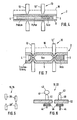
- the crystallization device 2 consists of an elastic tube 8 that can be closed laterally, for example with the aid of glass plugs 4, 6.
- the tube 8 must be chemically inert and transparent.
- a particularly suitable material for the hose is silicone rubber
- the hose 8 is divided by a clamping device 10 with several clamping points 12, 12 'into several chambers 14, 14', 14,, in which, depending on the method used, there is a salt solution, a protein solution, a buffer solution or a gas Clamping elements are adjustable so that the respective chamber size can be selected as desired.
- the crystallization device 2 can further comprise a compression device 16 which exerts constant pressure on the hose 8.
- This compression device 16 can consist of an elastic material. By means of them, it is to be prevented, if necessary, that the transition from the rest phase, which is shown in FIGS. 7, 9a, 10a, 11a and 12a, into the crystallization phase, which is shown in FIGS. 4, 9b, 10b, 11b, 12b and also in FIGS. 8 and 13, a negative pressure builds up in the chambers in the various crystallization processes in order to prevent any outgassing in the crystallization chambers. When the clamping devices are loosened, the chamber volume increases due to the disappearance of the clamping points.
- the clamping device 10 can be a press clamping device 18 with conical clamping elements 20, 20 'according to FIG. 5 or a loop clamping device 22 according to FIG. 6.
- the press clamping device is also shown in all other figures except for FIG. 6.
- the press clamping device can for example have a clamping plate 24, to which the clamping elements 20, 20 'are attached and which is adjustable via a spindle 28 driven by a motor 26 or the like.
- Fig. 8 A base plate 32 arranged on a fixed support 30 can serve as a press counter-bearing.
- the clamping elements 20, 20 'opposite clamping elements can be provided, as is shown schematically in FIGS. 4, 5, 7 and 9 to 12.
- the compression device 16 is located between the clamping plate 24 and the hose 8.
- Each sample field can have its own temperature control device 29, with the aid of which both temperature gradients and constant temperatures for the crystallization tubes 8 can be adjusted.
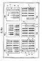
- FIG. 13 shows a plan view of a sample plane with six sample fields 38a, b, c, d, e, f.
- FIG. 13 shows that hoses of different sizes and working according to different crystallization processes can be provided per field.
- the arrangement of the tubes remains largely free through the use of a perforated grid for fixing the samples. The aim of this is to enable each experimenter to work out the optimal length and thickness of his crystallization chamber in his soil experiments without having to change the hardware for flight experiments.
- the clamping levels with the clamping elements for either the press clamp or the loop clamp have the same grid.
- the loop clamping device 22 consists of a sleeve 40, which is on the base plate 32 of the sample, cf. Fig. 8, is fixed in a hole of a hole pattern.
- a sleeve 40 By the sleeve is a loop 42 drawn, for example, from a nylon thread or wire 43, which surrounds the hose 8.
- the loop 42 With the aid of a threaded rod 44, the loop 42 can be drawn in, as is also shown in FIG. 6.
- actuating a knurled nut 46 the loop can be enlarged or reduced to adapt to different diameters of the tubes 8.
- the threaded rods 44 of the individual clamping points can be operated simultaneously, which is not shown.
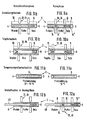
- the crystallization device described can be used for various processes, as is shown schematically in FIGS. 9a, b, 10a, b, 11a, b and 12a, b.
- FIG. 9a and 9b show the application in the salting-out process.
- the tube 8 is closed at both ends with two planar glass plugs 4, 6.
- the tube 8 is divided into three chambers 14, 14 ', 14' 'for a protein solution, a buffer solution and a salt solution with the aid of the clamping device 10.
- Fig. 9b shows the crystallization phase in which the different solutions can diffuse into each other within the tube 8.
- FIG. 10a and 10b show the application in the drop method, a microscopic salt solution being separated from a gas section in the resting phase (FIG. 10a) and the gas section being in turn separated from a very small liquid volume of the protein solution.
- the glass stopper on the side of the protein solution is conical.
- the surfaces around the drop 47 are constructed or treated in such a way that they have highly hydrophobic surface properties.
- the surface on the glass stopper should be slightly more wettable.
- 11a and 11b show the application of the crystallization device for the crystallization of proteins in the temperature gradient method. This procedure usually does not require chambering.
- the silicone tubes 8 are only closed by planar glass plugs.
- hose sizes Different chamber volumes can be realized by using different hose sizes.
- Preferred dimensions of the hoses are 20 to 80 mm in length, 1.5 to 5 mm in outside diameter and 1 to 4 mm in inside diameter.
- the size of the chambers themselves can be set differently by moving the clamping elements relative to one another and to the ends of the hoses.
- the clamping device 10 is particularly important for the use of the tubes 8 for crystallization under weightless conditions, in order to avoid equilibration of the liquids separated from one another in the tubes beforehand.
- the clamping device meets the following requirements:
- a narrow-band clamping has the advantage that after the crystallization process has ended, when the clamping elements are closed again, the crystals formed are obtained largely undisturbed. This is usually problematic in that crystal growth may be at the Liquid-gas or liquid-liquid interface occurs at which the clamping also begins.
- 18, 19 and 20 now show special designs of the tubes 8, by means of which the narrow-band nature of the clamping is supported or is achieved in the first place.
- the tubes 8 have an outer and / or inner bead 54, 56 directly next to the clamping, as is shown in FIG. 18.
- FIG. 19 shows another stiffening means, in the form of a reinforcing ring 58, 60 glued on the inside or outside.
- FIG. 20 shows a stiffening means in the form of a sleeve 62 for keeping the tubes 8 round next to the clamping point.
- FIGS. 14 and 15 In order to ensure safe opening of the clamp after closing, designs are provided which are shown in FIGS. 14 and 15.
- the clamping elements which are preferably designed as clamping wedges 20, 20 ', elastic elements 64 are installed for this purpose, by which a limitation of the pressure of the clamping elements is achieved.
- This pressure limitation can be designed so that a geometrical adaptation of each clamp to the different hose diameters is not necessary. This is possible if the elastic element allows sufficient room for compression.
- the clamping wedges 20, 20 ' are connected to one another on the sides by an elastic means 66, for example a nylon cord, a textile tape or the like.
- an elastic means 66 for example a nylon cord, a textile tape or the like.
- this means is loosely arranged around the clamped hose 8, as shown in FIG. 15.
- the band is taut and exerts a lateral pressure on the still compressed tube 8, which forces the opening of the tubes 8, but at least supports it.
- the base plates 32, on which the hoses 8 are mounted have a narrow hole pattern 68.
- the holes 68 of this grid of holes serve to receive elastic clips 70 which are used to hold the hoses. 16 and 17 show such a clip 70, which here has the shape of a clip.
- These elastic clips 70 are attached to the ends of the hoses and hooked into the hole pattern 68.
- the purpose of this elastic clamping of the hose ends is that when the clamps are opened, these elastic clamps continue to exert a positive pressure on the hose 8 and ensure that, on the one hand, the hose can be opened more easily and, on the other hand, there is no negative pressure in the hose which could possibly lead to degassing of the liquids contained in the hose.
- This design creates a simple means for locking the clamping device, which can be released after installing the clamped hoses between the base plate and the displaceable clamping plate. After the installation of the clamped hoses between the base plate and the displaceable clamping plate, the clamping plate is lowered to such an extent that it compresses the clamping elements or the clamping wedges somewhat via their elastic elements 64, so that the locking of the individual clamps can then be released. After installation, the clamping of the individual hoses is determined by the position of the sliding clamping plate relative to the base plate.
- the elastic clamps 70 for hose attachment and the clamping elements 20, 20 'for dividing the hoses 8 into the different crystallization chambers fit into the hole pattern 68 of both the base plate 32 and the displaceable clamping plate 24.
- the fastening of the clamping elements and the clamps can be done differently.
- the clips 70 for hose attachment which in the present case have approximately the shape of a clip, can be clamped into the hole pattern if they are suitably deformed. It is also possible to use these brackets for hose attachment and the clamping elements for dividing the hoses into several crystallization chambers with small screws on the two plates 32 and 24.
- Another possibility is to fasten the clamps and clamping elements to the two plates with adhesive after positioning by means of pins in the perforated grid.
- the clamping device should be released approximately two hours after the rocket has started and should extend over a period of four hours.
- the liquid shifts that occur here are below the diffusion rate of the substances.
- the formation described can ensure that the crystals formed at the liquid-liquid or liquid-gas interfaces are maintained during the reentry phase (crystals also form in the middle of the individual liquid spaces).
- the clamping elements are closed again, this process takes place in the opposite direction, and there is a volume shift from the clamps in the direction of the elastic hose fastening clamps. It can be assumed that crystals, which have formed below the clamping elements and are very endangered by the clamping action, move in the direction of the hose ends due to the volume shift. Crystals that have formed further away from the clamping elements are not at risk.
- the crystallization device described is particularly suitable for examining the crystallization of proteins under weightless conditions, since the experimenters can, after completing successful soil tests, initially and in a fairly simple and effective manner prevent the crystallization process of tubes made with fillings using the described device by means of the described clamping device.
Landscapes
- Chemical & Material Sciences (AREA)
- Crystallography & Structural Chemistry (AREA)
- Organic Chemistry (AREA)
- Engineering & Computer Science (AREA)
- Materials Engineering (AREA)
- Metallurgy (AREA)
- Chemical Kinetics & Catalysis (AREA)
- General Chemical & Material Sciences (AREA)
- Health & Medical Sciences (AREA)
- Clinical Laboratory Science (AREA)
- Peptides Or Proteins (AREA)
- Crystals, And After-Treatments Of Crystals (AREA)
- Sampling And Sample Adjustment (AREA)
Applications Claiming Priority (4)
| Application Number | Priority Date | Filing Date | Title |
|---|---|---|---|
| DE3726765 | 1987-08-12 | ||
| DE3726765 | 1987-08-12 | ||
| DE19873738840 DE3738840A1 (de) | 1987-08-12 | 1987-11-16 | Kristallisationseinrichtung |
| DE3738840 | 1987-11-16 |
Publications (2)
| Publication Number | Publication Date |
|---|---|
| EP0303224A2 true EP0303224A2 (fr) | 1989-02-15 |
| EP0303224A3 EP0303224A3 (fr) | 1989-04-19 |
Family
ID=25858532
Family Applications (1)
| Application Number | Title | Priority Date | Filing Date |
|---|---|---|---|
| EP88112911A Withdrawn EP0303224A3 (fr) | 1987-08-12 | 1988-08-09 | Dispositif de cristallisation |
Country Status (5)
| Country | Link |
|---|---|
| US (1) | US5009861A (fr) |
| EP (1) | EP0303224A3 (fr) |
| JP (1) | JPH0692437B2 (fr) |
| CA (1) | CA1322449C (fr) |
| DE (1) | DE3738840A1 (fr) |
Cited By (2)
| Publication number | Priority date | Publication date | Assignee | Title |
|---|---|---|---|---|
| WO1992014869A1 (fr) * | 1991-02-25 | 1992-09-03 | Schering Corporation | Cristallisation de macromolecules biologiques en microgravite |
| FR2698382A1 (fr) * | 1992-11-25 | 1994-05-27 | Nissan Motor | Cellule pour croissance cristalline. |
Families Citing this family (22)
| Publication number | Priority date | Publication date | Assignee | Title |
|---|---|---|---|---|
| US5139605A (en) * | 1986-05-07 | 1992-08-18 | Messerschmitt-Bolkow-Blohm Gmbh | Method and apparatus for crystallizing substances dissolved in a liquid at zero-gravity |
| US6027565A (en) * | 1991-02-25 | 2000-02-22 | Bugg; Charles E. | Method and apparatus for crystalizing macromolecules in microgravity |
| US5427335A (en) * | 1992-07-13 | 1995-06-27 | The University Of Tennessee Research Corporation | Method for producing extreme microgravity in extended volumes |
| US5256241A (en) * | 1992-08-28 | 1993-10-26 | The United States Of America As Represented By The Administrator Of The National Aeronautics And Space Administration | Method for controlling protein crystallization |
| JP3094880B2 (ja) * | 1995-03-01 | 2000-10-03 | 住友金属工業株式会社 | 有機化合物の結晶化制御方法およびそれに用いる結晶化制御用固体素子 |
| US20020164812A1 (en) * | 1999-04-06 | 2002-11-07 | Uab Research Foundation | Method for screening crystallization conditions in solution crystal growth |
| US7247490B2 (en) * | 1999-04-06 | 2007-07-24 | Uab Research Foundation | Method for screening crystallization conditions in solution crystal growth |
| WO2000060345A1 (fr) * | 1999-04-06 | 2000-10-12 | University Of Alabama At Birmingham Research Foundation | Procede de criblage des conditions de cristallisation dans une solution de tirage d'un cristal |
| US7244396B2 (en) * | 1999-04-06 | 2007-07-17 | Uab Research Foundation | Method for preparation of microarrays for screening of crystal growth conditions |
| US7214540B2 (en) * | 1999-04-06 | 2007-05-08 | Uab Research Foundation | Method for screening crystallization conditions in solution crystal growth |
| US7250305B2 (en) * | 2001-07-30 | 2007-07-31 | Uab Research Foundation | Use of dye to distinguish salt and protein crystals under microcrystallization conditions |
| US6630006B2 (en) * | 1999-06-18 | 2003-10-07 | The Regents Of The University Of California | Method for screening microcrystallizations for crystal formation |
| US6750064B2 (en) * | 2000-12-28 | 2004-06-15 | S.S.C.I. Inc. | Methods of screening for possible solid forms |
| US7670429B2 (en) | 2001-04-05 | 2010-03-02 | The California Institute Of Technology | High throughput screening of crystallization of materials |
| DE10144526A1 (de) * | 2001-09-10 | 2003-04-03 | Lpkf Laser & Electronics Ag | Verfahren und Vorrichtung zur Bestimmung der mittleren Leistung eines Lasers |
| US20070026528A1 (en) * | 2002-05-30 | 2007-02-01 | Delucas Lawrence J | Method for screening crystallization conditions in solution crystal growth |
| US20040007672A1 (en) * | 2002-07-10 | 2004-01-15 | Delucas Lawrence J. | Method for distinguishing between biomolecule and non-biomolecule crystals |
| US7198759B2 (en) * | 2002-07-26 | 2007-04-03 | Applera Corporation | Microfluidic devices, methods, and systems |
| EP1630263A4 (fr) * | 2003-05-27 | 2009-06-03 | Japan Aerospace Exploration | Appareil et procede pour former des cristaux de biopolymere |
| US8018588B2 (en) * | 2007-06-06 | 2011-09-13 | Aptuit, Inc. | Sample holder and sample preparation device |
| US20090010388A1 (en) * | 2007-06-06 | 2009-01-08 | Stahly Barbara C | Microplate and methods of using the same |
| WO2020170321A1 (fr) * | 2019-02-19 | 2020-08-27 | 株式会社コンフォーカルサイエンス | Dispositif de cristallisation de biopolymère |
Citations (2)
| Publication number | Priority date | Publication date | Assignee | Title |
|---|---|---|---|---|
| US2603667A (en) * | 1950-01-26 | 1952-07-15 | Phillips Petroleum Co | Fractional crystallization |
| FR1112171A (fr) * | 1953-12-08 | 1956-03-09 | Western Electric Co | Procédé de redistribution des éléments de systèmes soluté-solvant fusibles |
Family Cites Families (3)
| Publication number | Priority date | Publication date | Assignee | Title |
|---|---|---|---|---|
| US3036894A (en) * | 1958-10-22 | 1962-05-29 | Jasper A Forestiere | Method of using testing containers |
| US4263010A (en) * | 1979-10-31 | 1981-04-21 | University Patents, Inc. | Control method and apparatus for crystallizer process control |
| JPS62106000A (ja) * | 1985-10-30 | 1987-05-16 | Fujitsu Ltd | 生体高分子結晶自動作製装置 |
-
1987
- 1987-11-16 DE DE19873738840 patent/DE3738840A1/de active Granted
-
1988
- 1988-08-09 US US07/229,950 patent/US5009861A/en not_active Expired - Fee Related
- 1988-08-09 EP EP88112911A patent/EP0303224A3/fr not_active Withdrawn
- 1988-08-11 JP JP63199047A patent/JPH0692437B2/ja not_active Expired - Lifetime
- 1988-08-12 CA CA000574699A patent/CA1322449C/fr not_active Expired - Fee Related
Patent Citations (2)
| Publication number | Priority date | Publication date | Assignee | Title |
|---|---|---|---|---|
| US2603667A (en) * | 1950-01-26 | 1952-07-15 | Phillips Petroleum Co | Fractional crystallization |
| FR1112171A (fr) * | 1953-12-08 | 1956-03-09 | Western Electric Co | Procédé de redistribution des éléments de systèmes soluté-solvant fusibles |
Non-Patent Citations (2)
| Title |
|---|
| JOURNAL OF CRYSTAL GROWTH, Band 42, Nr. 1, Dezember 1977, Seiten 253-258, North-Holland Publishing Co., Amsterdam, NL; N. ZELINGHER et al.: "Sodium acetate tri-hydrate whiskers" * |
| JOURNAL OF CRYSTAL GROWTH, Band 76, 1986, Seiten 663-672, North-Holland, Amsterdam. NL; W. LITTKE et al.: "Protein single crystal growth under microgravity" * |
Cited By (2)
| Publication number | Priority date | Publication date | Assignee | Title |
|---|---|---|---|---|
| WO1992014869A1 (fr) * | 1991-02-25 | 1992-09-03 | Schering Corporation | Cristallisation de macromolecules biologiques en microgravite |
| FR2698382A1 (fr) * | 1992-11-25 | 1994-05-27 | Nissan Motor | Cellule pour croissance cristalline. |
Also Published As
| Publication number | Publication date |
|---|---|
| EP0303224A3 (fr) | 1989-04-19 |
| DE3738840A1 (de) | 1989-02-23 |
| US5009861A (en) | 1991-04-23 |
| JPH0692437B2 (ja) | 1994-11-16 |
| JPH01139102A (ja) | 1989-05-31 |
| CA1322449C (fr) | 1993-09-28 |
| DE3738840C2 (fr) | 1991-04-11 |
Similar Documents
| Publication | Publication Date | Title |
|---|---|---|
| DE3738840C2 (fr) | ||
| DE60034033T2 (de) | Vorrichtung zum screening von kristallisierungsbedingungen in lösungen zur kristallzüchtung | |
| CH465271A (de) | Kolonnenverschluss für Säulenchromatograph | |
| DE4109908A1 (de) | Anordnung zur pruefung von halbleiter-wafern oder dergleichen | |
| DD201563A5 (de) | Chirurgische spreizvorrichtung zur heilung der wirbelsaeule | |
| DE4109866A1 (de) | Reparaturstand mit richtrahmen | |
| EP3175279A1 (fr) | Microscope optique muni d'une platine porte-échantillon pour la cryomicroscopie | |
| DE659092C (de) | Einschleusvorrichtung fuer an der Pumpe betriebene Korpuskularstrahlapparate | |
| DE2716287A1 (de) | Vielpol-massenfilter | |
| DE4217324C1 (de) | Vorrichtung zum Einführen von medizinischen Instrumenten in einen lebenden Körper | |
| DE60225968T2 (de) | Vorrichtung und Verfahren zur Bereitstellung von Bodenproben | |
| EP0244867B1 (fr) | Procédé et dispositif de cristallisation d'une substance dissoute dans un liquide à l'état d'apesanteur | |
| DE2447508B2 (de) | Vorrichtung zur Injizierung einer Probe in den kontinuierlichen Lösungsmittelstrom bei einem Flüssigchromatographiesystem | |
| DE2510683C3 (de) | Stabschleuse für Vakuumkammern | |
| DE3220619C2 (de) | Vorrichtung zur Handhabung von Dünnschnitten, insbesondere Kryoschnitten, und Verfahren zur Gefriertrocknung solcher Dünnschnitte | |
| AT521524B1 (de) | Gasmischvorrichtung zur Kalibrierung von Gasanalysatoren | |
| DE102016203891A1 (de) | Verfahren zur Durchführung einer NMR-Messung, Probenkopfanordnung für ein NMR-Spektrometer und NMR-Spektrometer-Anordnung | |
| EP3756797A1 (fr) | Procede d'essai de nouvelles compositions de materiaux pour la fusion laser sur lit de poudre, et dispositif concu a cet effet | |
| DE3603278C1 (de) | Einrichtung zum Bedecken des in einer Gehäusewand eines Mikrotoms vorgesehenen länglichen Schlitzes | |
| DE102018001735A1 (de) | Montagevorrichtung zur gleichzeitigen Anordnung einer Mehrzahl von Ölspritzdüsen an einer Brennkraftmaschine | |
| DE102008058068A1 (de) | Vorrichtung und ein Verfahren zur Bereitstellung einer vorgebbaren Konzentration mindestens einer Komponente in einem flüssigen Medium | |
| DE2356918A1 (de) | Kollimator-wechsel- und speichervorrichtung fuer strahlungsabbildungssysteme | |
| DE1772250A1 (de) | Objekttraeger fuer Mikroskope | |
| DE102015108898A1 (de) | Universal-Probenhalter für Biomakromoleküle in der Röntgenstrukturanalyse | |
| DE2417377A1 (de) | Hyperfeinfilter fuer die resonanzlinien von caesium und rubidium |
Legal Events
| Date | Code | Title | Description |
|---|---|---|---|
| PUAI | Public reference made under article 153(3) epc to a published international application that has entered the european phase |
Free format text: ORIGINAL CODE: 0009012 |
|
| AK | Designated contracting states |
Kind code of ref document: A2 Designated state(s): AT BE CH ES FR GB IT LI NL SE |
|
| PUAL | Search report despatched |
Free format text: ORIGINAL CODE: 0009013 |
|
| AK | Designated contracting states |
Kind code of ref document: A3 Designated state(s): AT BE CH ES FR GB IT LI NL SE |
|
| 17P | Request for examination filed |
Effective date: 19890816 |
|
| 17Q | First examination report despatched |
Effective date: 19910212 |
|
| STAA | Information on the status of an ep patent application or granted ep patent |
Free format text: STATUS: THE APPLICATION IS DEEMED TO BE WITHDRAWN |
|
| 18D | Application deemed to be withdrawn |
Effective date: 19920508 |