EP0303085A2 - Méthode et dispositif pour la mise en place souterraine de tuyaux de chauffage - Google Patents
Méthode et dispositif pour la mise en place souterraine de tuyaux de chauffage Download PDFInfo
- Publication number
- EP0303085A2 EP0303085A2 EP88111905A EP88111905A EP0303085A2 EP 0303085 A2 EP0303085 A2 EP 0303085A2 EP 88111905 A EP88111905 A EP 88111905A EP 88111905 A EP88111905 A EP 88111905A EP 0303085 A2 EP0303085 A2 EP 0303085A2
- Authority
- EP
- European Patent Office
- Prior art keywords
- mole
- arrangement
- heating pipes
- heating
- laying
- Prior art date
- Legal status (The legal status is an assumption and is not a legal conclusion. Google has not performed a legal analysis and makes no representation as to the accuracy of the status listed.)
- Withdrawn
Links
Images


Classifications
-
- E—FIXED CONSTRUCTIONS
- E21—EARTH OR ROCK DRILLING; MINING
- E21B—EARTH OR ROCK DRILLING; OBTAINING OIL, GAS, WATER, SOLUBLE OR MELTABLE MATERIALS OR A SLURRY OF MINERALS FROM WELLS
- E21B7/00—Special methods or apparatus for drilling
- E21B7/20—Driving or forcing casings or pipes into boreholes, e.g. sinking; Simultaneously drilling and casing boreholes
- E21B7/205—Driving or forcing casings or pipes into boreholes, e.g. sinking; Simultaneously drilling and casing boreholes without earth removal
-
- F—MECHANICAL ENGINEERING; LIGHTING; HEATING; WEAPONS; BLASTING
- F16—ENGINEERING ELEMENTS AND UNITS; GENERAL MEASURES FOR PRODUCING AND MAINTAINING EFFECTIVE FUNCTIONING OF MACHINES OR INSTALLATIONS; THERMAL INSULATION IN GENERAL
- F16L—PIPES; JOINTS OR FITTINGS FOR PIPES; SUPPORTS FOR PIPES, CABLES OR PROTECTIVE TUBING; MEANS FOR THERMAL INSULATION IN GENERAL
- F16L1/00—Laying or reclaiming pipes; Repairing or joining pipes on or under water
- F16L1/024—Laying or reclaiming pipes on land, e.g. above the ground
- F16L1/028—Laying or reclaiming pipes on land, e.g. above the ground in the ground
Definitions
- the invention relates to a method and a device for the underground laying of heating pipes.
- the object of the invention is to provide a method and a device for the underground laying of heating pipes, which allow the laying of heating pipes with a minimum of time with minimal disturbance of the earth's surface, especially in sports fields without impairing lawns.
- this object is achieved in that at least one heating pipe is connected vibration-free to at least one mole arrangement of a traction device, that the at least one mole arrangement is set to a predetermined laying depth of the associated heating pipe, and that the at least one is preset to the laying depth by means of the pulling device Mole arrangement and the associated heating pipe are pulled through the ground with a tractor.
- the device according to the invention for solving the stated problem is characterized by a pulling device which can be coupled to a tractor and has at least one mole arrangement which can be connected to one end of at least one heating pipe to be laid without vibration, and a depth adjustment device for setting the at least one mole arrangement to the laying depth of the associated heating pipe .
- FIG. 1 shows a schematic side view of a tractor 1 to which a traction device 2 with conventional connecting means 3 is coupled.
- a frame 4 of the pulling device 2 is supported on the earth surface 7 by wheels 5 via a depth adjustment device 6.
- a conventional vibration device 12 is provided on the frame 4 of the pulling device 2.
- the frame 4 carries at least one downwardly extending mole arrangement 10, which is connected at its lower end to one end of a heating pipe 40 in a vibration-free manner. Depending on the respective laying conditions, one or more moles can be attached to the frame 4 orders 10 parallel and spaced apart. In the illustrated embodiment, cf. Fig.2, the frame 4 is provided with three parallel mole arrangements 10.
- each mole arrangement 10 is assigned a leading cutting wheel 8 which cuts through the lawn area and which can be adjusted to the intended working depth with a depth-adjustable holder 9.
- the frame 4 is shown in a rear view in FIG.
- the depth adjustment device 6 which acts on both sides of the frame 4 and mechanically e.g. is designed with a spindle drive, hydraulically or pneumatically in the usual manner and is therefore not described in detail.
- Three mole arrangements 10 are arranged in parallel at a distance from one another and connected to the vibration or double vibration device 12.
- the cutting wheels not shown in this figure, are arranged on a carrier 13 which is adjusted to the desired working depth of the cutting wheels by the depth-adjustable brackets 9 arranged on both sides of the frame 4.
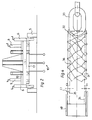
- FIG. 3 shows in detail a side view of a mole arrangement 10, which consists of a mole carrier 20 and a mole body 11.
- the mole carrier 20 is firmly connected to the frame 4 by conventional fastening means at the upper end and extends from the mole body 11 to the upper end.
- the mole carrier 20, starting from the mole body 11, runs at an angle forward and upward in the running direction and thus forms a front part 21 inclined forward and upward with a cutting edge 22. Wear strips 23 welded on from the cutting edge 22 extend at least over the front part 21.
- the mole carrier 20 is connected to the mole body 11 via rounded side parts 25.
- a fastening part 28 On the rear side of the mole carrier 11 in the running direction, at the level of the mole carrier 11 there is a fastening part 28 with a recess 29 for receiving the shackle of a chain which is connected to the mole body 11.
- the shackle is fastened with a bolt in a bore 28 'of the fastening part 28.
- the mole support 20 and the mole body 11 are designed in such a way that there is only a very low draft resistance during the laying of the heating pipes 40.
- FIG. 4 shows a view of the vibration-free connecting means between the heating pipe 40 to be laid and the fastening part 28 of the mole body 11.
- These connecting means contain a chain 30, which is fastened to the fastening part 28 with the fastening means described above, and a steel plug or a steel pipe 31 whose outer diameter is adapted to the inner diameter of the heating pipe 40.
- the steel tube 31 is firmly connected at one end 32 to an end link 33 of the chain 30, for example by welding.
- the the other end 34 of the steel tube 31 is inserted into the heating tube 40 and is provided with a through hole 35 which is aligned with a corresponding through hole 41 in the heating tube 40.
- the heating pipe 40 is fastened to the steel pipe 31 by a bolt (not shown) which penetrates the through-holes 35 and 41 and is secured with a conventional anti-vibration nut.
- the steel tube 31 is provided on the outside in the region between the through bore 35 and one end 32 with welded-on wear strips 36.
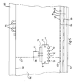
- a trench 62 is dug, in which an inflow line 63 and an outflow line 64 of the heater are laid, each of which is provided with heating pipe connections 65.
- a predetermined number of, for example, five heating pipes 40 are fastened to the pulling device 2 via five mole arrangements 10, and the frame 4 is set to the prescribed working depth by means of the depth adjusting devices 6.
- the heating pipes 40 are then drawn through the ground at the intended working depth, the heating pipes 40 being laid in parallel and at a predetermined lateral distance.
- the laying is facilitated by the actuation of the vibrating device 12, the leading cutting wheels 8 keeping damage to the lawn area to a minimum.
- the tractor 1 is expediently ent during the laying process with the aid of a direction indicator 66 long a straight tensioned rope 67, whereby a straight-line installation and alignment of the installed heating pipes 40 is ensured.
- a further trench 69 is dug, which receives connecting pipe loops 70 between the ends of adjacent heating pipes 40.
- the frame 4 is raised so that the heating pipes 40 can be detached from the associated mole arrangements 10 and further laid by hand. This way, larger breaks in the edge of the trench can be safely avoided.
- Adjacent heating pipes 40 are then connected to one another in the usual way by the pipe loops 70, and the opposite ends of the heating pipes 40 are connected to the inflow line 63 and outflow line 64, respectively.
- the trenches 62 and 69 are then filled in again. It is advisable to roll the lawn area 60, which is slightly undulated after the heating pipes 40 have been laid, as soon as possible, as a result of which the lawn area 60 is leveled completely and permanently again.
Landscapes
- Engineering & Computer Science (AREA)
- Life Sciences & Earth Sciences (AREA)
- Geology (AREA)
- Mining & Mineral Resources (AREA)
- General Engineering & Computer Science (AREA)
- Physics & Mathematics (AREA)
- Environmental & Geological Engineering (AREA)
- Fluid Mechanics (AREA)
- General Life Sciences & Earth Sciences (AREA)
- Geochemistry & Mineralogy (AREA)
- Mechanical Engineering (AREA)
- Road Paving Structures (AREA)
Applications Claiming Priority (2)
| Application Number | Priority Date | Filing Date | Title |
|---|---|---|---|
| DE3726532 | 1987-08-10 | ||
| DE19873726532 DE3726532A1 (de) | 1987-08-10 | 1987-08-10 | Verfahren und vorrichtung zur unterirdischen verlegung von heizungsrohren |
Publications (2)
| Publication Number | Publication Date |
|---|---|
| EP0303085A2 true EP0303085A2 (fr) | 1989-02-15 |
| EP0303085A3 EP0303085A3 (fr) | 1990-12-12 |
Family
ID=6333426
Family Applications (1)
| Application Number | Title | Priority Date | Filing Date |
|---|---|---|---|
| EP19880111905 Withdrawn EP0303085A3 (fr) | 1987-08-10 | 1988-07-23 | Méthode et dispositif pour la mise en place souterraine de tuyaux de chauffage |
Country Status (2)
| Country | Link |
|---|---|
| EP (1) | EP0303085A3 (fr) |
| DE (1) | DE3726532A1 (fr) |
Cited By (1)
| Publication number | Priority date | Publication date | Assignee | Title |
|---|---|---|---|---|
| EP0588051A1 (fr) * | 1992-09-16 | 1994-03-23 | Witzenmann GmbH Metallschlauch-Fabrik Pforzheim | Procédé pour la pose d'un conduit de chauffage sans excavation, conduit de chauffage et dispositifs pour la mise en oeuvre de ce procédé |
Families Citing this family (1)
| Publication number | Priority date | Publication date | Assignee | Title |
|---|---|---|---|---|
| CN110822165A (zh) * | 2019-11-15 | 2020-02-21 | 中国电建集团华东勘测设计研究院有限公司 | 一种非开挖柔性管管道更换破裂刀具 |
Family Cites Families (5)
| Publication number | Priority date | Publication date | Assignee | Title |
|---|---|---|---|---|
| AT272015B (de) * | 1965-11-30 | 1969-06-25 | Nikex Nehezipari Kulkere | Vorrichtung zur Verlegung von unterirdischen Leitungen |
| FR2314602A1 (fr) * | 1975-06-11 | 1977-01-07 | Inst Francais Du Petrole | Dispositif pour enterrer des elements flexibles de grande longueur |
| US4245705A (en) * | 1979-04-07 | 1981-01-20 | Kubota, Ltd. | Apparatus for taking off vibratory power for tractor |
| EP0094694B2 (fr) * | 1980-12-02 | 1993-07-14 | British Gas Corporation | Insertion de canalisations principales |
| US4685832A (en) * | 1985-08-19 | 1987-08-11 | Decker William J | Underground pipe and cable laying machine |
-
1987
- 1987-08-10 DE DE19873726532 patent/DE3726532A1/de active Granted
-
1988
- 1988-07-23 EP EP19880111905 patent/EP0303085A3/fr not_active Withdrawn
Cited By (1)
| Publication number | Priority date | Publication date | Assignee | Title |
|---|---|---|---|---|
| EP0588051A1 (fr) * | 1992-09-16 | 1994-03-23 | Witzenmann GmbH Metallschlauch-Fabrik Pforzheim | Procédé pour la pose d'un conduit de chauffage sans excavation, conduit de chauffage et dispositifs pour la mise en oeuvre de ce procédé |
Also Published As
| Publication number | Publication date |
|---|---|
| DE3726532C2 (fr) | 1989-11-02 |
| DE3726532A1 (de) | 1989-02-23 |
| EP0303085A3 (fr) | 1990-12-12 |
Similar Documents
| Publication | Publication Date | Title |
|---|---|---|
| DE69702126T2 (de) | Leitplanken, verfahren zur erstellung und maschine zur durchführung des verfahrens | |
| DE3828595C2 (fr) | ||
| DE2309014C2 (de) | Planiergerät | |
| DE7529603U (de) | An einer zugmaschine anbringbare materialhandhabungsvorrichtung | |
| DE2631667A1 (de) | Verfahren zum verlegen eines produktionsrohres unter einem hindernis | |
| CH632307A5 (de) | Baugrubenverbau fuer einen graben oder ein loch. | |
| EP0303085A2 (fr) | Méthode et dispositif pour la mise en place souterraine de tuyaux de chauffage | |
| DE2616348A1 (de) | Vorrichtung fuer den grabenverbau | |
| DE2625300A1 (de) | Verfahren und geraet zum verlegen eines relativ steifen rohres oder kabels in den boden | |
| DE69331552T2 (de) | Mehrwellenaushubsvorrichtung | |
| DE68913825T2 (de) | Verfahren zum Ausführen einer Spundwand und dazu gebrauchtes Hilfsprofil. | |
| DE3823784C2 (fr) | ||
| DE202017006870U1 (de) | Vorrichtung für die Sicherung einer Grube oder eines Grabens | |
| DE2057263A1 (de) | Vorrichtung zum Abstuetzen von Grabenwaenden | |
| EP3613906B1 (fr) | Système de charrue de tuyau et / ou de câble et procédé | |
| DE2821235C2 (de) | Türzarge | |
| DE4303742C1 (de) | Verfahren zur Entwässerung von Böden mit hohem Wasseranteil | |
| WO2002066741A1 (fr) | Unité de ripage pour déplacer une voie de convoyeur | |
| DE2639014A1 (de) | Vorrichtung zum verlegen von erdkabeln o.dgl. | |
| DE3735679A1 (de) | Anordnung zum anheben des grundwasserspiegels, verfahren zur herstellung der anordnung und vorrichtung zur durchfuehrung dieses verfahrens | |
| DE2248321C3 (de) | Bodenbelag, insbesondere für behelfsmäßige Fahrbahnen und Vorrichtung zum Verlegen des Bodenbelags | |
| DE69331879T2 (de) | Mehrarmige ausschachtungsvorrichtung | |
| AT289444B (de) | Anordnung zur Beregnung von landwirtschaftlichen Flächen | |
| EP0158313A2 (fr) | Dispositif pour l'ameublissement du sous-sol adaptable sur véhicules agricoles et machines mobiles | |
| DE1534354C (de) | Fahrbahnbelag aus Metallplatten |
Legal Events
| Date | Code | Title | Description |
|---|---|---|---|
| PUAI | Public reference made under article 153(3) epc to a published international application that has entered the european phase |
Free format text: ORIGINAL CODE: 0009012 |
|
| AK | Designated contracting states |
Kind code of ref document: A2 Designated state(s): AT BE CH DE ES FR GB GR IT LI LU NL SE |
|
| PUAL | Search report despatched |
Free format text: ORIGINAL CODE: 0009013 |
|
| AK | Designated contracting states |
Kind code of ref document: A3 Designated state(s): AT BE CH DE ES FR GB GR IT LI LU NL SE |
|
| STAA | Information on the status of an ep patent application or granted ep patent |
Free format text: STATUS: THE APPLICATION IS DEEMED TO BE WITHDRAWN |
|
| 18D | Application deemed to be withdrawn |
Effective date: 19910613 |