EP0293543B2 - Bildvervielfältigungsgerät - Google Patents
Bildvervielfältigungsgerät Download PDFInfo
- Publication number
- EP0293543B2 EP0293543B2 EP88100066A EP88100066A EP0293543B2 EP 0293543 B2 EP0293543 B2 EP 0293543B2 EP 88100066 A EP88100066 A EP 88100066A EP 88100066 A EP88100066 A EP 88100066A EP 0293543 B2 EP0293543 B2 EP 0293543B2
- Authority
- EP
- European Patent Office
- Prior art keywords
- area
- copy
- subroutine program
- areas
- control
- Prior art date
- Legal status (The legal status is an assumption and is not a legal conclusion. Google has not performed a legal analysis and makes no representation as to the accuracy of the status listed.)
- Expired - Lifetime
Links
- 230000015572 biosynthetic process Effects 0.000 claims 1
- 239000002245 particle Substances 0.000 description 42
- 238000012546 transfer Methods 0.000 description 40
- 230000000994 depressogenic effect Effects 0.000 description 35
- 239000002131 composite material Substances 0.000 description 33
- 230000004913 activation Effects 0.000 description 25
- 239000003086 colorant Substances 0.000 description 25
- 230000002093 peripheral effect Effects 0.000 description 24
- 238000000034 method Methods 0.000 description 13
- 238000010586 diagram Methods 0.000 description 11
- 230000007246 mechanism Effects 0.000 description 10
- 238000012545 processing Methods 0.000 description 10
- 238000013500 data storage Methods 0.000 description 8
- 238000004364 calculation method Methods 0.000 description 7
- 238000004891 communication Methods 0.000 description 5
- 238000010276 construction Methods 0.000 description 5
- 230000033001 locomotion Effects 0.000 description 5
- 230000003287 optical effect Effects 0.000 description 5
- 230000008569 process Effects 0.000 description 5
- 102100037013 Neuroblastoma breakpoint family member 9 Human genes 0.000 description 4
- 102100029099 Nucleolar complex protein 3 homolog Human genes 0.000 description 3
- 230000008859 change Effects 0.000 description 3
- 238000012937 correction Methods 0.000 description 3
- 210000005069 ears Anatomy 0.000 description 3
- 230000000694 effects Effects 0.000 description 3
- 230000004907 flux Effects 0.000 description 3
- 230000006870 function Effects 0.000 description 3
- 238000005286 illumination Methods 0.000 description 3
- 238000005192 partition Methods 0.000 description 3
- 239000000843 powder Substances 0.000 description 3
- 238000007639 printing Methods 0.000 description 3
- 230000009467 reduction Effects 0.000 description 3
- 230000002441 reversible effect Effects 0.000 description 3
- 230000002457 bidirectional effect Effects 0.000 description 2
- 230000005540 biological transmission Effects 0.000 description 2
- 239000000969 carrier Substances 0.000 description 2
- 238000004886 process control Methods 0.000 description 2
- 102100024522 Bladder cancer-associated protein Human genes 0.000 description 1
- 230000003213 activating effect Effects 0.000 description 1
- 238000013459 approach Methods 0.000 description 1
- 230000006866 deterioration Effects 0.000 description 1
- 230000008030 elimination Effects 0.000 description 1
- 238000003379 elimination reaction Methods 0.000 description 1
- 239000000696 magnetic material Substances 0.000 description 1
- 239000000203 mixture Substances 0.000 description 1
- 238000000926 separation method Methods 0.000 description 1
- 230000001360 synchronised effect Effects 0.000 description 1
- 230000007704 transition Effects 0.000 description 1
- 230000000007 visual effect Effects 0.000 description 1
Images


Classifications
-
- G—PHYSICS
- G03—PHOTOGRAPHY; CINEMATOGRAPHY; ANALOGOUS TECHNIQUES USING WAVES OTHER THAN OPTICAL WAVES; ELECTROGRAPHY; HOLOGRAPHY
- G03G—ELECTROGRAPHY; ELECTROPHOTOGRAPHY; MAGNETOGRAPHY
- G03G15/00—Apparatus for electrographic processes using a charge pattern
- G03G15/50—Machine control of apparatus for electrographic processes using a charge pattern, e.g. regulating differents parts of the machine, multimode copiers, microprocessor control
-
- G—PHYSICS
- G03—PHOTOGRAPHY; CINEMATOGRAPHY; ANALOGOUS TECHNIQUES USING WAVES OTHER THAN OPTICAL WAVES; ELECTROGRAPHY; HOLOGRAPHY
- G03G—ELECTROGRAPHY; ELECTROPHOTOGRAPHY; MAGNETOGRAPHY
- G03G15/00—Apparatus for electrographic processes using a charge pattern
- G03G15/01—Apparatus for electrographic processes using a charge pattern for producing multicoloured copies
-
- G—PHYSICS
- G03—PHOTOGRAPHY; CINEMATOGRAPHY; ANALOGOUS TECHNIQUES USING WAVES OTHER THAN OPTICAL WAVES; ELECTROGRAPHY; HOLOGRAPHY
- G03G—ELECTROGRAPHY; ELECTROPHOTOGRAPHY; MAGNETOGRAPHY
- G03G15/00—Apparatus for electrographic processes using a charge pattern
- G03G15/36—Editing, i.e. producing a composite image by copying one or more original images or parts thereof
-
- G—PHYSICS
- G03—PHOTOGRAPHY; CINEMATOGRAPHY; ANALOGOUS TECHNIQUES USING WAVES OTHER THAN OPTICAL WAVES; ELECTROGRAPHY; HOLOGRAPHY
- G03G—ELECTROGRAPHY; ELECTROPHOTOGRAPHY; MAGNETOGRAPHY
- G03G15/00—Apparatus for electrographic processes using a charge pattern
- G03G15/50—Machine control of apparatus for electrographic processes using a charge pattern, e.g. regulating differents parts of the machine, multimode copiers, microprocessor control
- G03G15/5016—User-machine interface; Display panels; Control console
- G03G15/502—User-machine interface; Display panels; Control console relating to the structure of the control menu, e.g. pop-up menus, help screens
Definitions
- the present invention relates to an image duplicating apparatus and particularly to an electrophotographic image duplicating apparatus such as a copying apparatus of the type having editing image forming and data input capabilities. More particularly, the present invention relates to an electrophotographic image duplicating apparatus having an editing mode of copying operation in which images within any one or more of a plurality of designated copy/erase areas may be copied and printed in any color or colors or may be blanked out or erased.
- An electrophotographic copying apparatus having editing image forming and data input capabilities is known which has an editing mode of copying operation in which images of a given document can be copied and printed in a plurality of colors.
- An advanced version of such a copying apparatus further allows designation of a localized area so that the images within the designated area may be copied and printed in any desired color or may be erased.
- Such a copying apparatus is disclosed in, for example, Japanese Provisional Patent Publication (Kokai) 60-237469.
- a prior-art copying apparatus of this type however has an inconvenience in that only a single color can be used for the designated area and, thus it is not allowed to use one color for one designated area and another color for another designated area. If it is desired to have images within two different areas be printed respectively in different colors, the operator is compelled to use two consecutive cycles of copying operation. During the first cycle of operation, the images in one designated area are duplicated and printed in one color and the images in another designated area are duplicated and printed in another color during the second cycle of operation. Laborious and time-consuming efforts are thus required for the operator to produce a copy with two or more localized areas printed in different colors, respectively.
- the two or more localized areas are at least partly overlapped by each other or one localized area in its entirety is contained within the coverage of another localized area, then the result will be that the images in the overlapped portions of the areas will be printed in two colors, which gives rise to deterioration in the contrast of the resultant duplicate images.
- JP-A-62-85265 Another image duplicating apparatus is disclosed in JP-A-62-85265. 85265.
- images are formed in different colours for a first area which is closed and a second area outside the closed area, respectively. However, if the second area is closed or is enclosed with another area no image forming condition is given to such a third area.
- a further image duplicating apparatus wherein a designated duplicating area is enclosed within another duplicating area is disclosed in GB-A-2 101 840.
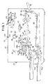
- an image duplicating apparatus (hereinafter referred to as copying apparatus) embodying the present invention comprises a housing 20 having an upper panel portion formed in part by a transparent document table 22. A sheet of document (not shown) bearing images to be reproduced is to be placed on this document table 22.
- the document sheet placed on the document table 22 is optically scanned by illumination with light from an optical scanning system 24.
- a resultant beam of light carrying information representative of the images on the scanned document sheet is directed to an image reproduction system 26.
- the images carried by the light beam are thus provisionally recorded in the form of latent images, which are then developed into visible toner images through an electrophotographic process performed by the image reproduction system 26.
- the visible toner images are transferred to any record medium such as typically a copying sheet transported by a copy sheet feed mechanism 28 and the copy sheet now carrying the reproduced images is withdrawn out of the apparatus by means of an image-fixing and sheet discharge system 30.
- the optical scanning system 24 is of the slit exposure type and comprises an exposure lamp 32 from which a beam of light is incident on and reflected from the lower face of the document sheet on the table 22.
- the light reflected from the document sheet is incident onto an object mirror 34 and is re-directed rearwardly therefrom.
- the lamp 32 and object mirror 34 are carried on a common movable support member and, in combination, implement a document scanner 36 in the image duplicating apparatus embodying the present invention.
- the document scanner 36 is movable forwardly along the document table 22 as indicated by arrow a and backwardly as indicated by arrow b and has a predetermined home position with respect to the document table 22.
- the light reflected from the object mirror 34 is re-directed toward a mirror 38, which further re-directs the light downwardly toward another mirror 40.
- the mirrors 38 and 40 are also carried on a common movable support member and are movable together along the document table 22 into and out of predetermined home positions with respect to the table.
- the document scanner 36 and such a mirror pair 38 40 are operatively coupled to common drive means comprising a scanner drive motor 42 (M s ) implemented by a d.c. reversible motor so that the former is driven to travel at a speed doubling the speed of movement of the latter.
- the light travels forwardly along the document table 22 and passes through an image magnification reduction lens unit 44 to a mirror 46.
- the lens unit 44 is movable along the document table 22 independently of the document scanner 36 and mirror pair 38/40 with respect to the table 22.
- the lens unit 44 is thus operatively coupled to drive means comprising a lens drive motor 48 (M L ) which may be implemented by a d.c. stepper motor.
- M L lens drive motor
- the mirror 46 then re-directs the light downwardly to a mirror 50 which further re-directs the beam to a projecting mirror 52 from which the light is reflected downwardly as shown.
- the mirrors 46, 50 and 52 are herein assumed to be fixedly held with respect to the housing 20 but.
- each or any one of them may be arranged to be movable and,or rockable with respect to the housing 20.
- the lens unit 44 is assumed to include a cylindrical lens to permit an anamorphic editing mode of copying operation using independently different magnification ratios for two orthogonal axes.
- the image reproducing system 26 of the apparatus comprises a cylindrical image transfer drum 54 having a photoconductive peripheral surface.
- the light reflected downwardly from the projecting mirror 52 is projected onto the peripheral surface of this image transfer drum 54.
- the drum 54 is rotatable about its center axis in a direction indicated by arrow c and is driven for rotation at a fixed peripheral speed by means of a main drive motor (not shown) of the apparatus which may be provided independently of the scanner and lens drive motors.
- the image reproducing system 26 further comprises a main charger 56 to sensitize the photoconductive peripheral surface of the image transfer drum 54.
- a main charger 56 to sensitize the photoconductive peripheral surface of the image transfer drum 54.
- an image developing stage 58 which is herein shown as including two, upper and lower developing units 58 a and 58 b detachably mounted in the apparatus and each having a stock of a developer powder composed of a mixture of electrostatically charged carrier particles and black or otherwise colored toner particles.
- red-colored toner particles are stored in the upper developing unit 58 a and black-colored toner particles are stored in the lower developing unit 58 b .
- a drive motor 60 (M O ) by means of which the rotatable members forming part of each of the developing units 58 a and 58 b are to be driven for rotation for applying toner particles to the peripheral surface of the image transfer drum 54 from a selected one of the developing units 58 a and 58 b , as will be described in more detail.
- Posterior to the developing stage 58 in turn is provided an image transfer charger 62 which is operative to charge the copy sheet so that the toner images formed on the drum 54 are transferred to the copy sheet.
- the copy sheet thus having the toner images carried thereon is cleared of charges by a separation charger 64 which is located posterior to the transfer charger 62.
- drum cleaner unit 66 which removes any residual toner particles from the peripheral surface of the drum 54.
- Posterior to this cleaner unit 66 in turn is located a charge eraser lamp 68 which irradiates the cleaned peripheral surface of the drum 54 to eliminate the charges which may be left thereon.
- the paper feed mechanism 28 of the copying apparatus is provided in conjunction with first and second paper supply cassettes 70 a and 70 b detachably fitted to the housing 20 and which respectively have encased therein stocks of copy sheets of different sizes.
- the paper feed mechanism 28 per se comprises first and second paper feed rollers 72 and 74 associated with the cassettes 70 a and 70 b , respectively. Each of these rollers 72 and 74 is driven for rotation for picking up copying sheets one after another from the stack of paper in the associated one of the cassettes 70 a and 70 b .
- a copying sheet picked up from the first paper supply cassette 70 a by means of the first paper feed roller 72 is passed through a first pair of guide rollers 76 and further through a second pair of guide rollers 78 toward the image transfer drum 54.
- a copying sheet picked up from the second paper supply cassette 70 b by means of the second paper feed roller 74 is passed through a third pair of guide rollers 80 toward the image transfer drum 54.
- a manual paper feed slot in the housing 20 so that a copying sheet may be manually inserted into the housing 20 through this tray and transported toward the drum 54 through the third pair of guide rollers 80.
- timing rollers 82 Immediately posterior to the developing stage 58 is provided a pair of timing rollers 82.
- the timing rollers 82 are driven for rotation at a timing synchronized with the movement of the document scanner 36 so that the copying sheet is correctly transferred to the drum 54.
- the timing rollers 82 are further operative to rectify the direction of the copying sheet to be fed to the peripheral surface of the drum 54.
- Each of the paper feed rollers 66 and 68, each of the guide roller pairs 76, 78 and 80, and the pair of timing rollers 76 are driven from a main drive motor of the apparatus by means of respectively associated clutches (not shown).
- a copy-sheet transport belt assembly 84 is positioned posterior to the area where the copy sheet is to be separated from the image transfer drum 54.
- the copy sheet separated from the drum 54 is thus conveyed rearwardly through the belt assembly 84 to an image fixing assembly 86 provided at the rear of the belt assembly 84.
- the toner particles carried on the copy sheet are thus thermally fused and the toner images fixed on the copy sheet by means of this image fixing assembly 86.
- the copy sheet released from the image fixing assembly 86 is withdrawn from the apparatus through first and second pairs of paper discharge rollers 88 and 90 and a paper discharge tray 92 attached to the housing 20 through a slot provided in the rear panel portion of the housing 20.
- the copying apparatus embodying the present invention is assumed to further comprises a duplex/composite copy paper feed system 94 which is usually used for producing printed images on the reverse face of the copy sheet which has printed images already produced on its front face.
- a duplex/composite copy paper feed system 94 comprises a series of roller pairs arranged away from the first pair of paper discharge rollers 88 toward the second pair of paper guide rollers 78 so that the copy sheet which has been passed through the paper discharge rollers 88 is turned out and passed through the paper guide rollers 78 toward the timing rollers 82.
- Past the first pair of paper discharge rollers 88 is thus provided a two-way guide member 96 movable between a position to pass a copy sheet from the rollers 88 to the rollers 90 as indicated by broken lines and a position to pass a copy sheet from the rollers 88 to the rollers of the duplex/composite copy paper feed system 94 as indicated by full lines.
- the duplex/composite copy paper feed system 94 is arranged to be also operable for a two-cycle two-colored editing mode of copying operation in which images within one specified area of a copying sheet are to be printed in one color and images within another specified area of the sheet are to be printed in another color on the same side of the sheet on which the images within the former area have been printed.
- the copying apparatus embodying the present invention has capabilities to reproduce images in an editing mode within a specified area or areas of a copying sheet.
- Such an editing mode of operation is performed with use of a selective charge eraser unit 98 located posterior to the main charger 56 and anterior to the developing stage 58.
- the copying apparatus embodying the present invention further has capabilities to print reproduced images in two different colors (which may include black) on one face of a single copying sheet during a single cycle of copying operation.
- Such a copying operation is herein referred to as single-cycle two-colored mode of copying operation and may be selected in addition to the above mentioned editing mode of copying operation.
- the apparatus embodying the present invention comprises a color shift control device 100 by means of which a desired boundary between two differently colored zones can be manually defined during an editing mode of copying operation.
- Such a color shift control device 100 comprises a guide member (not shown) extending along a longitudinal edge of the document table 22, a slide member 102 slidable on the guide member, and a light interceptor element 104 slidable on the lower face of the document table 22.
- the light interceptor element 104 is movable with the slide member 102 and is thus capable of intercepting the beam of light from the exposure lamp 32 at any location to which the slide member 102 is manually moved in a direction parallel with the direction in which a document is to be scanned on the document table 22.
- the apparatus embodying the present invention further comprises various sensors and detectors which include a boundary detector 106 implemented typically by a photoelectric transducer and carried on or otherwise movable with the document scanner 36.
- the boundary detector 106 is responsive to interception of light by the light interceptor element 104 and produces an output signal (S BL ) of a logic "1" bit indicative of the location to which the slide member 102 is manually moved.
- the signal S BL produced by the boundary detector 106 is thus representative of the location of the boundary line defined between desired zones of a copying sheet which are to be printed in different colors, respectively, one of which may be black and the other of which may be, for example, red.
- the sensors and detectors provided in the apparatus further include first and second color sensors 108 a and 108 b arranged in conjunction with the upper and lower developing units 58 a and 58 b . respectively.
- Each of the developing units 58 a and 58 b has attached thereto a magnet element (not shown) located specifically to the particular unit to enable the associated color sensor 108 a or 108 b to discriminate one of the developing units 58 a and 58 b from the other depending on the locations of the magnet elements on the units 58 a and 58 b .
- the upper and lower developing units 58 a and 58 b have stored therein red and black colored toner particles. respectively.
- the first color sensor 108 a associated with the upper developing unit 58 a is operative to produce a signal of a logic "1" bit and the second color sensor 108 b associated with the lower developing unit 58 b is operative to produce a signal of a logic "0" bit.
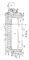
- FIGs. 2, 3 and 4 show the detailed construction of the developing stage 58 which forms part of the image reproducing system 26 of the apparatus embodying the present invention.
- the two developing units 58 a and 58 b of the stage 58 being essentially similar in construction, the detailed construction of only the lower developing unit 58 b is herein shown as being representative of the two.
- the developing unit 58 b comprises a housing 110 defining a storage chamber 112 and a transfer chamber 114. These chambers 112 and 114 are separate from each other by a partition wall 110 c forming part of the housing 110 and communicate with each other at the opposite longitudinal ends of the partition wall 110 c as will be seen from Fig. 3. Positioned within the storage chamber 112 is a feed screw 116 rotatable in the direction of arrow d about an axis parallel with the axis of rotation of the image transfer drum 54 and having opposite end portions 116 a and 116 b journaled in opposite end walls 110 a and 110 b , respectively, of the housing 110.
- the developer powder stored in the storage chamber 112 is thus distributed from the vicinity of one end of the partition wall 110 c to the vicinity of the other along the screw 116 and is fed into the toner transfer chamber 114 as the screw 116 is driven for rotation in the storage chamber 112.
- a transfer roller 118 and a hollow, cylindrical toner applicator sleeve 120 each positioned in parallel with the feed screw 116.
- the transfer roller 118 is positioned between the feed screw 116 and applicator sleeve 20 and also has opposite end portions 118 a and 118 b journaled in the opposite end walls 110a and 110 b , respectively, of the housing 110.
- the transfer roller 118 is rotatable in the direction of arrow e about an axis parallel with the axis of rotation of the image transfer drum 54 so that the developer powder fed from the feed screw 116 is passed by the roller 118 over to the applicator sleeve 120 as the screw 116 and roller 118 are driven for rotation respectively in the directions of arrows d and e as indicated.
- the applicator sleeve 120 is positioned close to the image transfer drum 54 to form a gap D s between the peripheral surface of the drum 54 and the outer peripheral surface of the applicator sleeve 120.
- the sleeve 120 has an end portion 120 a journalled in one end wall 110 a of the housing 110 and is also rotatable in the direction of arrow f about an axis parallel with the axis of rotation of the image transfer drum 54.
- the end portion 116 a of the feed screw 116 and the end portion 118 a of the transfer roller 118 have respectively carried thereon pulleys between which is passed an endless drive belt 122.
- the end portion 118 a of the transfer roller 118 and the end portion 120 a of the applicator sleeve 120 have respectively carried thereon pulleys between which is passed an endless drive belt 124.
- the end portion 118 a of the transfer roller 118 thus carrying the pulleys associated with both of the drive pulleys 122 and 124 has further carried thereon a gear 126 which is in mesh with a gear 128 carried on the output shaft of the previously mentioned drive motor 60 (M D ).
- the applicator sleeve 120 is constructed of a non-magnetic material having a finely roughened outer peripheral surface and has accommodated therein a cylindrical magnetic rotor 130.
- the magnetic rotor 130 is rotatable within the applicator sleeve 120 about the center axis of the sleeve 120 and has opposite end portions 130 a and 130 b , one journalled in a socket 120 a formed in an end wall portion of the sleeve 120 and the other journalled in the end wall 110 b of the housing 110 as indicated by broken lines in Fig. 2.
- Fig. 2 As will be seen from Fig.
- the magnetic rotor 122 has embedded therein a total of five permanent magnet members each extending axially of the rotor 130 and consisting of four magnet members S 1 , N 1 , S 2 and N 2 having alternately opposite polarities and a magnet member N 3 having a negative polarity.
- the magnet members S 1 , N 1 , S 2 , N 2 and N 3 are angularly spaced apart from each other about the center axis of the rotor 130 with, particularly, the magnet members N 1 and S 1 angularly spaced apart an angle ⁇ 1 of, for example, 80 degrees.
- magnet members may be selected such that the magnet member N 1 has a flux density of 1000 Gauss, each of the magnet members S 1 and S 2 has a flux density of 800 Gauss and each of the magnet members N 2 and N 3 has a flux density of 500 Gauss.
- the magnetic rotor 130 is rockable about the center axis thereof between an operative angular position having the magnet member N 1 located in proximity to the gap D s between the sleeve 120 and drum 54 as shown and an inoperative angular position turned through 40 degrees counterclockwise in Fig. 3 from the operative angular position and having the magnet members S 1 and N 1 equally spaced apart from the gap D s .
- an ear-height limit member 132 attached to the housing 110 and located to form an ear-height limiting gap D E over the outer peripheral surface of the applicator sleeve 120.
- the ear-height limit member 132 is adapted to limit the heights of the "ears" of carrier particles produced on the outer peripheral surface of the sleeve 120.
- the developing unit 58 b further comprises a control lever 134 fixedly carried on the end portion 120 b of the magnetic rotor 130 and having diametrically opposite arm portions extending from the end portion 130 b .
- a helical tension spring 136 is anchored at one end to one arm portion of the control lever 134 and at the other to an anchor pin 138 projecting from the wall portion 110 b of the housing 110.
- the control lever 134 and accordingly the magnetic rotor 130 are thus biased to turn in the direction of arrow g (Fig. 4) about the center axis of the rotor 130.
- a solenoid-operated actuator 140 has a plunger 140 a pivotally connected to the other arm portion of the control lever 134, which is thus forced to turn from the operative angular position to the inoperative angular position thereof against the force of the spring 136 when the actuator 140 is energized.
- the magnet member N 1 in the rotor 130 is located close to the gap D s between the applicator sleeve 120 and image transfer drum 54.
- the toner particles on the ears of carriers attached to the outer peripheral surface of the applicator sleeve 120 by means of the magnet member N 1 may be transferred to the peripheral surface of the drum 54.
- the solenoid-operated actuator 140 is then de-energized and accordingly the magnetic rotor 130 is caused to turn to the inoperative angular position thereof by the force of the spring 136, the magnet members S 1 and N 1 are equally spaced apart from the gap D s so that there will be no ears of toner-carrying carriers formed on peripheral surface of the applicator sleeve 120 in proximity to the gap D s .
- Fig. 5 shows the general configuration of a control panel 200 which forms part of the apparatus embodying the present invention.
- the control panel 200 comprises a print start switch 202 to enable the apparatus to start duplicating operation and a set of numerical switches 204 allocated to numerals 1, 2, ... and 0, respectively, and used to enter a selected quantity of copy sheets to be printed.
- the quantity of copy sheets thus entered from the numerical switches 204 is displayed on a numerical data display window 206 and can be cleared from a clear/stop switch 208 (C.S) which may be used also for cancelling the instruction once entered from the print start switch 202.
- C.S clear/stop switch 208
- another document sheet may be duplicated in an interrupt mode entered at an interrupt request switch 210 (IR).
- the numerical switches 204 are to be used not only for entering a selected quantity of copy sheets to be printed but for entering numerical data representative of the coordinates to define a desired edited copy/erase area to be specified during an editing copying mode of operation.
- the numerical data thus entered from the switches 202 are also displayed on the numerical data display window 206.
- the size of copy sheets to be used can be selected at a manual paper-size select switch 212 (SIZE) from among a predetermined number of sizes available.
- the selected size of copy sheets is displayed by any of paper-size indicators which are collectively indicated at 212 a .
- the paper-size select switch 212 is, in effect, operative to select one of the paper supply cassettes 70 a and 70 b currently installed on the apparatus shown in Fig. 1.
- a set of magnification ratio select switches 214 for selecting any of predetermined magnification ratios for copying, the switches 214 having respectively associated indicators 216 a .
- print density increment and decrement switches 216 with respectively associated indicators 216 a to permit manual selection of a desired print density for the copy sheets to be printed.
- the print density is stepwise incremented with one of the switches 216 depressed or decremented with the other of the switches 216 depressed.
- the color of the imaged to be printed can be selected from among different available colors at a color select switch 220 having associated color indicators 220 a allocated to different print colors such as black, red (or magenta) and yellow as previously noted.
- the color select switch 220 is in effect operative to select one or two of the developing units 58 a and 58 b of the image developing stage 58 of the apparatus shown in Fig. 1.
- switches and indicators for selecting the editing mode of copying operation and entering data necessary for executing the editing copying operation.
- These switches and indicators include a single-cycle two-colored mode select switch 222 for requesting execution of the previously defined single-cycle two-colored mode of copying operation, and zoom switches 224 for continuously varying the coordinate values and/or the magnification ratio once entered for editing mode of copying operation.
- the zoom switches 224 may be used to enter coordinate data for each of the desired edited copy;erase areas 1 and 2.
- the numerical data continuously selected by the switches 224 are displayed on the numerical data display window 206 for visual assistance to the operator.
- the switches and indicators for the editing copying mode of operation further include those arranged in an editing copy mode control section 226 and those arranged in an anamorphic magnification control section 228.
- the switches in the anamorphoscopic magnification control section 228 are used for the control of an anamorphoscopic editing mode of copying operation using independently different magnification ratios for two orthogonal axes.
- Fig. 6 shows in an enlarged scale the arrangement of the editing copy mode control section 226 of the described control panel 200.
- the editing copy mode control section 226 comprises an editing copy mode select switch 230 to enable entry of various instructions and data for an editing mode of copying operation.
- this editing copy mode select switch 230 is depressed to select the editing copying mode of operation, two of the indicators 220 a associated with the color select switch 220, viz, the indicators respectively allocated to the two different print colors (which are herein assumed to be red and black print colors. respectively) available by the upper and lower developing units 58 a and 58 b currently installed in the apparatus are turned on to illuminate or flicker.
- first to fourth indicators which consist of two x-coordinate indicators 232 a and 232 b and two y-coordinate indicators 232 c and 232 d .
- area display screen 234 on which a desired edited copy erase area R to be printed or erased is to be visually indicated.
- An xy-coordinate system is thus taken into account on this area display screen 234 as having an axis of abscissa corresponding to the direction of circumferential direction of the drum 54 and an axis of ordinate corresponding to the axial direction of the drum 54, with an origin at the right lower corner of the screen 234.
- the desired edited copy erase area R can thus be defined by the combination of x-coordinates X a and X b and y-coordinates Y c and Y d which may be designated from any of the numerical switches 204.
- the coordinates X a , X b , Y c and Y d may be designated one after another as the coordinate indicators 232 a and 232 b for the x-coordinates X a and X b and the coordinate indicators 232 c and 232 d for the y-coordinates Y c and Y d , respectively, are turned on to illuminate or flicker successively.
- Each of the indicators 232 a to 232 d thus provided in the control section 226 is of the type using a light emitting diode (LED).
- the images within each of the edited copy/erase areas 1 and 2 or the outside area of a copying sheet may be printed in any of the two colors available or may be blanked out or "erased". Entry of data for the edited copy erase areas 1 and 2 is requested by successive illumination of indicators 236 and 238, and entry of data for the outside area surrounding the edited copy erase areas 1 and 2 is indicated by illumination of an indicator 240.
- the coordinate data for each of the desired edited copy erase areas 1 and 2 are specified with use of the numerical keys 204 and or the zoom switches 224 and numerical data display window 206 and entered with an area data enter switch 242 depressed. If there are no data desired to be entered for one or both of the edited copy/erase areas 1 and 2 or for the outside area, an area cancel switch 244 may be depressed.
- the selection between the two colors for each of the three areas can be entered through a black select switch 246 and an area color switch 248.
- the area black switch 246 is used for selecting black as the print color in which the images within the desired edited copy/erase area 1 or 2 or in the outside area are to be printed.
- the area color switch 248 is used for selecting another print color such as red (or yellow) as the color in which the images within the desired edited copy/erase area 1 or 2 or in the outside area are to be printed.
- the selection of the erasure of one or more of the three areas can be entered through an area erase switch 250 which may be used where it is desired to erase the images within one or both of the desired edited copy/erase area 1 or 2 or the outside area.
- the switches 242 to 250 have associated indicators 242 a to 250 a , respectively, each of which is to be turned on to flicker when the associated switch is depressed.
- Fig. 7 shows, in conjunction with the selective charge eraser unit 98 incorporated in the copying apparatus illustrated in Fig. 1, an example of the edited copy/erase area which may be displayed on the display screen 234 in the editing copy mode control section 226 shown in Fig. 6.
- the charge eraser unit 98 is located anterior, in the direction c of rotation of the image transfer drum 54. to the path of light from the projecting mirror 52 to the peripheral surface of the drum 54. If desired, however, the charge eraser unit 98 may be located posterior, in the direction c of rotation of the drum 54, to the path of light from the projecting mirror 52 to the drum 54.
- the charge eraser unit 98 may be located anterior, in the direction c of rotation of the drum 54, to the path of light from the projecting mirror 52 to the drum 54.
- the charge eraser unit 98 is composed of a number of, typically sixty light emitter elements 252 (L o to L n , upwardly) arranged in a single linear array.
- the linear array of the light emitter elements 252 is positioned close to the peripheral surface of the image transfer drum 54 and extends in parallel to the axis of rotation of the drum 54.
- each of the light emitter elements 252 of the charge eraser unit 98 is implemented typically by a light emitting diode (LED).
- the adjacent light emitter elements L c to L d are activated to illuminate from time T a to time T b .
- the xy-coordinate system taken into account on the peripheral surface of the image transfer drum 54 is assumed to have its origin at the right lower corner of a copying paper P indicated by phantom lines.
- the direction indicated by arrow C along the axis of abscissa corresponds to the direction of rotation c of the image transfer drum 54 as shown in Fig. 1.
- the charges are caused to dissipate on the area S of the drum surface as defined by the four coordinate points (X a , Y c ), (X a , Y d ), (X b , Y c ) and (X b , Y d ) given by the x-coordinates X a and X b respectively corresponding to the times T a and T b and the y-coordinates Y c and Y d respectively corresponding to the light emitter elements L c and L d .
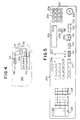
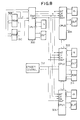
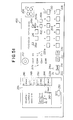
- Fig. 8 shows the general arrangement of a control circuit which may be used to achieve the functions hereinbefore described with reference to Figs. 2 to 7.
- the control circuit comprises first, second, third and fourth microprocessors 300, 302, 304 and 306 (hereinafter referred to as CPU1, CPU2, CPU3 and CPU4. respectively).
- Each of the second to fourth CPU2 302 to CPU4 306 has a clock input port (CK) and is supplied with clock pulses from the first CPU1 300 therethrough.
- Each of the CPU2 302 to CPU4 306 further has an interrupt port (INT) and may be interrupted by the first CPU1 therethrough as required by the CPU1.
- CK clock input port
- INT interrupt port
- the first to fourth CPU1 300 to CPU4 306 communicate with one another, through data input and output ports (S IN and S OUT ) and through bidirectional buses connecting the CPU2 302 to CPU4 306 together.
- a read-only memory 308 ROM
- RAM random-access memory
- the read-only memory 308 are stored the data and program to dictate the control procedures to be performed by the first CPU1 300.
- the first CPU1 300 is mainly predominant over the input and output of various signals from and to the control panel 200 and is operative as a master CPU to control the other CPU2 300 to CPU4 306 as required.
- the control and data signals supplied to the master CPU1 300 from the control panel 200 may thus be stored in the associated random-access memory 310 and may be processed in accordance with the data and program stored in the read-only memory 308.
- the second CPU2 302 is in control of the charge eraser unit 98 as well as the image reproducing system 26, paper feed mechanism 28 and image-fixing and sheet discharge system 30.
- the second CPU2 302 is thus responsive to the control and data signals supplied from the editing copy mode control section 226 of the control panel 200 to control the selective activation of the light emitter elements 252 of the charge eraser unit 98.
- the second CPU2 302 is further connected to an eraser control circuit 312 to control the charge eraser unit 98 and a random-access memory 314 storing the data and program to dictate the selective activation of the light emitter elements 252 of the charge eraser unit 98.
- the third CPU3 304 is predominant over the operation of the optical scanning system 24, while the fourth CPU4 306 may be used to control the duplex and synthetic copying modes of operation of the apparatus having such capabilities.
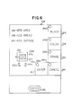
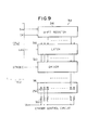
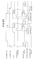
- Fig. 9 shows an example of the general configuration of the control circuit 312 for the charge eraser unit 98 incorporated in the apparatus embodying the present invention.
- the control circuit 312 comprises a shift register 316 responsive to the data signals S IN and clock pulses CK supplied from the second CPU2.
- the data signals S IN are supplied from the CPU2 in the form of a serial bit sequence, which is converted into parallel bit information by means of the shift register 316.
- the data thus expressed in the form of parallel bit information is stored into a latch circuit 318 enabled by a latch enable signal (LEN) received from the second CPU2.
- a driver circuit 320 composed of a number of parallel switch elements (not shown) is responsive to the logic "1" and "0" bits of information thus output from the latch circuit 318.
- the individual switch elements of the driver circuit 320 are connected to the light emitting diodes respectively implementing the light emitter elements 252 of the charge eraser unit 98.
- the driver circuit 320 is enabled by strobe signals from the CPU2 for selectively activating the light emitter elements 252 in accordance with the logic "1" and "0" bits of information output from the latch circuit 318.
- the light emitting diodes implementing the light emitter elements 252 are connected to a supply voltage source Vcc respectively through current limiting resistors 322 as shown.
- the data to be fed from the CPU2 to the shift register 316 are formulated on the basis of the size the document to be duplicated, the specified coordinates defining the desired edited copy erase area R, the selected mode of copying mode, and the selected color or colors in which the copy images are to be printed.
- Such data are output from the CPU2 at timings controlled by various internal timers of the CPU2 and flags indicative of various states or events which may occur in the apparatus as will be described in more detail.
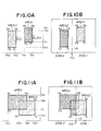
- Fig. 10A shows an example of the arrangement in which two separate edited copy erase areas consisting of areas 1 and 2 are specified for editing mode of copying operation on the xy-coordinate system of the display screen 234 in the editing copy mode control section 226 illustrated in Fig. 6.
- One edited copy erase area 1 is defined by four coordinate points P 1 (X a 1, Y c 1), P 2 (X a 1, Y d 1), P3 (X b 1, Y c 1) and P 4 (X b 1, Y d 1) and the other edited copy erase area 2 is defined by four coordinate points Q 1 (X a 2, Y c 2).
- the editing copy mode switch 230 is first depressed and then the copy erase area 1 is defined with the x- and y-coordinates X a 1, X b 1, Y c 1 and Y d 1 specified with use of the zoom switches 224 and display window 206 and entered with the editing copy mode select switch 230 depressed. Thereupon, the area black switch 246 or the area color switch 248 is depressed to request that the area 1 be printed in black or red or the area erase switch 250 is depressed to request that the area 1 be blanked out.
- the copy erase area 2 After the data for the editing mode of copying operation for the copy erase area 1 have thus been entered. a similar manipulative procedure is followed for the copy erase area 2 to enter the x- and y-coordinates X a 2. X b 2. Y c 2 and Y d 2 and request that the area 2 be printed in black or red or otherwise blanked out.
- the area black switch 246 or the area color switch 248 may be depressed to request that the outside area be printed in black or red or the area erase switch 250 is depressed to request that the area be blanked out.
- the area cancel switch 244 may be depressed to inform that there is no data to be entered for the unnecessary copy/erase area which may be the area 1 or the area 2.
- Fig. 10A After all the data for the desired edited copy erase areas 1 and 2 specified as shown, in Fig. 10A are entered, the print start switch may be depressed The images within one edited copy erase area 1 are now printed in black on one face of a copying sheet supplied from one of the paper supply cassettes 70 a and 70 b and the copy sheet thus bearing the images in the area 1 thereof is passed through the duplex/composite copy paper feed system 94 for another cycle of editing mode of copying operation. The images within the other edited copy/erase area 2 are thus printed in, for example, red on the same face of the copying sheet whereupon the copy sheet bearing the images in the areas 1 and 2 thereof is withdrawn to the discharge tray 92.
- Fig. 10B shows the images thus reproduced on a copy sheet by the two-cycle two-colored editing mode of copying operation performed in this manner.
- a similar duplicate copy can be produced in a single-cycle two-colored mode of copying operation selected from the single-cycle two-colored mode select switch 222.
- the slide member 102 of the color shift device 100 (Fig. 1) is moved to a position such that the desired edited copy/erase areas 1 and 2 are located within the differently colored zones 1 and 2, respectively, sectioned by the boundary (indicated by a dots-and-dash line) defined by the slide member 102 as shown.
- a single-cycle two-colored mode of copying operation can be selected in addition to an editing mode of copying operation.
- Fig. 11A shows an example of the arrangement in which two partly overlapped edited copy/erase areas consisting of areas 1 and 2 are specified for editing mode of copying operation.
- the x- and y-coordinates X a 1, X b 1, Y c 1 and Y d 1 defining the area 1 and the x- and y-coordinates X a 2, X b 2, Y c 2 and Y d 2 defining the area 2 are entered and the colors for the areas 1 and 2 designated in manners similarly to those described with reference to Fig. 10A.
- Fig. 11B shows the images thus reproduced on a copy sheet by a single-cycle two-colored mode of copying operation selected in addition to an editing mode of copying operation.
- the slide member 102 of the color shift device 100 is moved to a position such that the boundary between the differently colored zones 1 and 2 defined by the slide member 102 is located to intersect the overlapped portions of the edited copy/erase areas 1 and 2.
- those portions of the copy/erase areas 1 and 2 which are located in the colored zone 1 are printed in one color such as black and those portions of the areas 1 and 2 which are located in the colored zone 2 are printed in another color such as red.
- the edited copy/erase areas 1 and 2 specified as shown in Fig. 11A are to be reproduced in an editing mode of copying operation without selecting a single-cycle two-colored mode of copying operation. then the images within the copy erase area 1 are printed in one color such as black throughout the extent of the area 1 and the images within the portion of the copy erase area 2 outside the area 1 are printed in another color such as red.
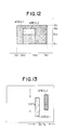
- Fig. 12 shows an example of the arrangement in which two edited copy/erase areas 1 and 2 consisting of one area 2 totally contained within the other area 1 are specified for editing mode of copying operation
- that portion of the copy erase area 1 which surrounds the copy/erase area 2 is to be printed in one color such as black and the copy/erase area 2 to be printed in another color such as red.
- Fig. 13 is a diagram showing the images reproduced on a copying sheet in an anamorphic editing mode of copying operation from the edited copy/erase areas specified as shown in Fig. 11A.
- magnification ratios of 50% and 100% are assumed to be selected for x-axis and y-axis. respectively, from the anamophoscopic magnification control section 228 of the control panel 200.
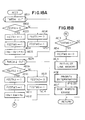
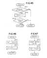
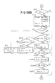
- Figs. 14A and 14B show the main routine program to be executed by the first or master CPU1 300.
- the routine program starts with the copying apparatus switched in and initializes the master CPU1 300 at a step AA01 so that all the copying conditions and modes of operation to be controlled by means of the CPU1 300 are selected in accordance with prescribed "default" rules.
- An internal timer of the system is then initiated at a step AA02 to count the time interval predetermined for a single complete iteration through the routine program.
- the master CPU1 300 may then execute a communication data updating subroutine program AA03 by which the data received by the CPU1 300 is transferred to an internal memory unit incorporated within the CPU1 and the data thus processed in the internal memory unit is transferred to the random access memory 310 for transmission to the other or slave CPU2 302, CPU3 304 and CPU4 306.
- the subroutine program AA03 may be followed by a decision subroutine program AA04 to monitor various operational conditions of the copying apparatus to determine whether or not a succession of process steps are to be followed subsequently by the CPU1 300.
- the master CPU1 300 may thereafter all the timers predominant over the timings at which various mechanical units and components of the apparatus are to operate during a single main routine period are started by a subroutine program AA05.
- the master CPU1 300 then executes various steps to process the instruction signals supplied from any of the switches on the control panel 200 as by a subroutine program AA06 and the data signals also supplied from the control panel 200 as by a subroutine program AA07 while generating instructions to update the numerical data to be displayed on the display window 206 of the control panel 200 as by a subroutine program AA08.
- the master CPU1 300 executes appropriate steps by a subroutine program AA09 to locate, remedy and/or display the failure or trouble involved.
- the master CPU1 300 may further execute an inter-CPU communication subroutine program AA10 for communicating with the slave CPU2 302, CPU3 304 and CPU4 306.
- the system Upon lapse of the predetermined time interval as detected at a step AA11 after the internal timer of the system has been initiated at the step AA02, the system reverts to the step AA02 and recycles the subroutine programs AA03 to AA10.
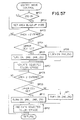
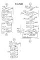
- Figs. 15A and 15B show the main routine program to be executed by the second CPU2 302 responsive to the control and data signals from the editing copy mode control section 226 of the control panel 200 to control the selective activation of the light emitter elements 252 of the charge eraser unit 98.
- the routine program starts with a step AB01 to initialize the CPU2 302 so that all the copying conditions and modes of operation to be controlled by means of the CPU2 302 are also selected in accordance with prescribed "default" rules.
- An internal timer of the system is then initiated at a step AB02 to count the time interval predetermined for a single complete iteration through the routine program.
- the second CPU2 302 may then execute a communication input updating subroutine program AB03 by which the data received by the CPU2 302 is transferred to an internal memory unit incorporated within the CPU2 302 and a communication output updating subroutine program AB04 by which the data thus processed in the internal memory unit is transferred via the master CPU1 300 to the random access memory 310 for transmission to the other slave CPU3 304 and CPU4 306.
- the subroutine program AB04 may be followed by a decision subroutine program AB05 to check into the data thus exchanged between the second CPU2 302 and any of the other CPU1 300, CPU3 304 and CPU4 306.
- the second CPU2 302 may thereafter execute another decision subroutine program AB06 to monitor some operational conditions of the copying apparatus to determine whether or not a succession of process steps are to be followed subsequently by the CPU2 302. Subsequently, instructions may be issued from the CPU2 302 by a subroutine program AB07 to control the image developing stage 58 of the apparatus in accordance with the instruction and data signals received from the control panel 200 directly or through the master CPU1 300.
- a subroutine program AB07 to control the image developing stage 58 of the apparatus in accordance with the instruction and data signals received from the control panel 200 directly or through the master CPU1 300.
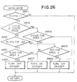
- the second CPU2 302 then proceeds to an editing mode control subroutine program AB08 to execute various steps for the control of the editing mode of copying operation in accordance with the instruction and data signals supplied from the editing copy mode control section 226 of the control panel 200.
- the details of this subroutine program AB08 will be described with reference to Fig. 16.
- the CPU2 302 further executes a process control subroutine program AB09 to control the optical scanning system 24, image reproducing system 26 and paper feed mechanism 28 and other strategic units of the copying apparatus and a process control subroutine program AB10 to process the signals supplied from, for example, various sensors and detectors including the sensors 108 a and 108 b associated with the developing units 58 a and 58 b and sensors associated with the paper supply cassettes 70 a and 70 b installed on the apparatus.
- the system Upon lapse of the predetermined time interval as detected at a step AB11 after the internal timer of the system has been initiated at the step AB02, the system reverts to the step AB02 and recycles the subroutine programs AB03 to AB10.
- the former communicates with the latter as schematically shown in Fig 15B.
- the editing mode control subroutine program AC03 starts with a decision step AC01 to determine on the basis of the data received from the master CPU 300 whether or not an editing copy mode of operation is currently requested from the control panel 200. If it is determined that there currently is a request for an editing copy mode of operation, the system proceeds to another decision step AC02 to confirm whether or not an edited copy/erase area is being created on the control panel 200. If the answer for this step AC02 is given in the affirmative, it is further queried at a step AC03 whether or not a status code SCEDIT currently has a logic "1" bit or logic "0" bit.
- step AC03 is followed by a subroutine program AC04 and if. conversely, it is found at the step AC03 that the status code SCEDIT currently present is of a logic "0" bit.
- step AC03 is followed by a subroutine program AC05.
- the details of the subroutine program AC04 will be hereinafter described with reference to Figs. 17A to 17C and the details of the subroutine program AC05 described with reference to Figs. 18A and 18B.
- the status code SCEDIT is shifted to a logic "0" bit as by a step AC06.
- the step AC06 is followed by a coordinate data input subroutine program AC07, the details of which will be later described with reference to Fig. 19.
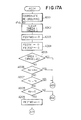
- Figs. 17A, 17B and 17C show the details of the subroutine program AC04 included in the editing mode control subroutine program AB08 hereinbefore described with reference to Fig. 16.
- the subroutine program AC04 starts in the presence of the status code SCEDIT of a logic "0" bit with a coordinate re-ordering subroutine program AD01 by which the two numerical values given by each of the x- and y-coordinate pairs defining each of the desired edited copy/erase areas 1 and 2 are re-ordered in accordance with a prescribed rule so that, for example, the coordinates of each pair are arranged in an increasing order.
- a coordinate re-ordering subroutine program AD01 will be later described with reference to Fig. 20.
- timers TMEDA1 and TMEDA2 predominant over the periods of time for the control of the editing mode of copying operation for the edited copy/erase areas 1 and 2, respectively, are cleared at a step AD02 and, thereafter, an instruction flag FEDTWD used for the activation of the charge eraser unit 98 is shifted to a logic "0" bit state at a step AD03.
- the instruction flag FEDTWD is, when shifted to a logic "1" bit state, effective to update the data for the selective activation of the light emitter elements 252 of the eraser unit 98.
- the step AD03 is followed by a step AD04 at which flags FEDTA1 and FEDTA2 respectively relating to the desired edited copy/erase areas 1 and 2 are shifted each to a logic "0" bit state. These flags FEDTA1 and FEDTA2 are shifted each to a logic "1" bit state when a sequence of control steps is in progress for an editing mode of copying operation for each of the copy/erase areas 1 and 2.
- step AD05 It is then queried at a step AD05 whether or not a request for the entry of data for the edited copy erase area 1 has been cancelled through the area cancel switch 244 in the editing copy mode control section 226 of the control panel 200. If it is found that at this step AD05 that such a request has not been cancelled. it is questioned at a step AD06 whether or not the two x-coordinates X a1 and X b1 entered for the edited copy erase area 1 are equal to each other. If the answer for this step AD06 is given in the negative. it is further questioned at a step AD07 whether or not the two y-coordinates Y c1 and Y d1 entered for the edited copy erase area 1 are equal to each other.
- step AD08 If the answer for this step AD07 is given also in the negative, it is tested at a step AD08 whether or not the x-coordinate X a1 of the copy erase area 1 is zero. If the answer for this step AD08 is given in the affirmative, the step AD08 is followed by a step AD09 by which the instruction flag FEDTWD is shifted to a logic "1" bit state. With the instruction flag FEDTWD thus shifted to a logic "1" bit state, the data for the selective activation of the light emitter elements 252 of the eraser unit 98 is updated.
- the step AD09 is followed through a connector AD1 by a step AD10 in the flowchart shown in Fig. 178 and, if it is found at the step AD08 that the x-coordinate X a1 of the copy/erase area 1 is not zero, the step AD08 is followed through a connector AD2 by a step AD11 in the flowchart of Fig. 17B.
- the subroutine program AC04 proceeds through a connector AD3 to a step AD13 in the flowchart of Fig. 17B.
- the flag FEDTA1 relating to the copy/erase area 1 is shifted to a logic "1" bit state to indicate that a sequence of control steps is in progress for the copy/erase area 1.
- the step AD10 is followed by a step AD11 by which a time data representative of the x-coordinate X b1 multiplied by the magnification ratio Nx selected for the direction of x-axis is set on the timer TMEDA1 for the edited copy/erase area 1.
- step AD08 when it is found at the step AD08 that the x-coordinate X a1 of the copy/erase area 1 is not zero, the step AD08 is followed by a step AD12 by which a time data representative of the x-coordinate X a1 multiplied by the magnification ratio Nx selected for the direction of x-axis is set on the timer TMEDA1 for the edited copy/erase area 1. Subsequently to the step AD11 or AD12 or to any of the steps AD05, AD06 and AD07 through the connector AD3, it is questioned at a step AD13 whether or not a request for the entry of data for the edited copy erase area 2 has been cancelled through the area cancel switch 244 in the editing copy mode control section 226.
- step AD13 If it is found that at this step AD13 that such a request has not been cancelled. it is questioned at a step AD14 whether or not the two x-coordinates X a2 and X b2 entered for the edited copy erase area 2 are equal to each other. If the answer for this step AD14 is given in the negative, it is further questioned at a step AD15 whether, or not the two y-coordinates Y c2 and Y d2 entered for the edited copy/erase area 2 are equal to each other. If the answer for this step AD15 is given also in the negative, it is tested at a step AD16 whether or not the x-coordinate X a2 of the copy/erase area 2 is zero.
- step AD16 is followed by a step AD17 by which the instruction flag FEDTWD is shifted to a logic "1" bit state to update the data for the selective activation of the light emitter elements 252 of the eraser unit 98.
- step AD17 is followed by a step AD18 by which the flag FEDTA2 relating to the copy/erase area 2 is shifted to a logic "1" bit state to indicate that a sequence of control steps is in progress for the copy/erase area 2.
- the step AD18 is followed by a step AD19 by which a time data representative of the x-coordinate X b2 multiplied by the magnification ratio N x selected for the direction of x-axis is set on the timer TMEDA2 for the edited copy/erase area 2.
- the step AD16 is followed by a step AD20 by which a time data representative of the x-coordinate X a2 multiplied by the magnification ratio Nx selected for the direction of x-axis is set on the timer TMEDA2 for the edited copy/erase area 2.
- the subroutine program AC12 proceeds to an eraser control buffer line memory initialize subroutine program AD21 and through a connector AD4 to a y-axis data calculation subroutine program AD22 in the flowchart of Fig. 17C.
- the buffer line memory is provided to control the activation of the charge eraser unit 98, though not shown in the drawings.
- the y-axis data calculation subroutine program AD22 is followed by a decision step AD23 at which it is confirmed whether or not the instruction flag FEDTWD has a logic "1" bit state effective to update the data for the selective activation of the light emitter elements 252 of the eraser unit 98. If the answer for this step AD23 is given in the affirmative, the flag FEDTWD is shifted to a logic "0" bit state at a step AD24 to inhibit repetition of unnecessary procedures.
- the step AD24 is followed by a priority determination subroutine program AD25 to set up the data for the selective activation of the light emitter elements 252 of the charge eraser unit 98 upon judgement of the order of priority between the edited copy/erase areas 1 and 2.
- the details of the priority determination subroutine program AD25 will be hereinafter described with reference to Fig. 24.
- the step AD24 and subroutine program AD25 are skipped over if it is found at the step AD23 that the flag FEDTWD has a logic "0" bit state.
- a side margin erase procedure is taken as by a subroutine program AD26 on the basis of the selected magnification ratio or ratios and selected size of copying sheet.
- the status code SCEDIT is shifted to a logic "1" bit at a step AD27 and. thereupon, the subroutine program AC04 is recycled from the step AD01.
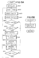
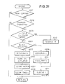
- Figs. 18A and 18B are flowcharts showing the details of the status code shift subroutine program AC05 included in the editing mode control subroutine program AB08 described with reference to Fig. 16.
- the subroutine program AC05 starts in the presence of the status code SCEDIT of a logic "1" bit with a decision step AE01 at which it is questioned whether or not the time which may have been counted by the timer TMEDA1 predominant over the period of time for the control of the editing mode of copying operation for the edited copy erase area 1 has lapsed.
- a decision step AE01 at which it is questioned whether or not the time which may have been counted by the timer TMEDA1 predominant over the period of time for the control of the editing mode of copying operation for the edited copy erase area 1 has lapsed.
- the answer for this step AE01 is given in the affirmative, it is tested at a step AE02 whether or not the flag FEDTA1 relating to the edited copy erase area 1 currently has a logic "0" bit state.
- the flag FEDTA1 is shifted to a logic "1" state at a step AE03 and thereafter at a step AE04 the instruction flag FEDTWD is shifted to a logic "1" bit state to update the data for the selective activation of the light emitter elements 252 of the eraser unit 98.
- the step AE04 is followed by a step AE05 at which a time data representative of the difference between the x-coordinates X a1 and X b1 multiplied by the magnification ratio N x selected for the direction of x-axis is set on the timer TMEDA1 for the edited copy/erase area 1.
- the flag FEDTA1 relating to the copy/erase area 1 currently has a logic "1" bit state
- the flag FEDTA1 is shifted to a logic "0" state at a step AE06 and thereafter at a step AE07 the instruction flag FEDTWD is shifted to a logic "1" bit state.
- step AE05 or AE07 when it is found at the step AE01 that the timer TMEDA1 is in operation, it is questioned at a step AE08 whether or not the time which may have been counted by the timer TMEDA2 predominant over the period of time for the control of the editing mode of copying operation for the edited copy/erase area 2 has lapsed.
- step AE08 When the answer for this step AE08 is given in the affirmative. it is tested at a step AE09 whether or not the flag FEDTA2 relating to the edited copy/erase area 2 currently has a logic "0" bit state.
- the flag FEDTA2 is shifted to a logic "1" state at a step AE10 and thereafter at a step AE11 the instruction flag FEDTWD is shifted to a logic "1" bit state to update the data for the selective activation of the light emitter elements 252 of the eraser unit 98.
- the step AE11 is followed by a step AE12 at which a time data representative of the difference between the x-coordinates X a2 and X b2 multiplied by the magnification ratio N x selected for the direction of x-axis is set on the timer TMEDA2 for the edited copy/erase area 2.
- the flag FEDTA2 when it is found at the step AE09 that the flag FEDTA2 relating to the copy/erase area 2 currently has a logic "1" bit state, the flag FEDTA2 is shifted to a logic "0" state at a step AE13 and thereafter at a step AE14 the instruction flag FEDTWD is shifted to a logic "1" bit state.
- the subroutine program AC05 jumps through a connector AE to a series of steps AE15 to AE19 in the flowchart of Fig. 18B.
- a decision step AE15 it is confirmed whether or not the instruction flag FEDTWD has a logic "1" bit state effective to update the data for the selective activation of the light emitter elements 252 of the eraser unit 98. If the answer for this step AE15 is given in the affirmative, the flag FEDTWD is shifted to a logic "0" bit state at a step AE16 to inhibit repetition of unncessary procedures.
- the step AE16 is followed by an eraser control buffer line memory initialize subroutine program AE17 and further by a priority determination subroutine program AE18 to set up the data for the selective activation of the light emitter elements 252 of the charge eraser unit 98 upon judgement of the order of priority between the edited copy/erase areas 1 and 2.
- the details of the buffer line memory initialize subroutine program AE17 will be hereinafter described with reference to Fig. 21 and the details of the priority determination subroutine program AE18 described with reference to Fig. 24.
- a side margin erase procedure is taken as by a subroutine program AE19 on the basis of the selected magnification ratio or ratios and selected size of copying sheet.
- the subroutine program AC05 Upon completion of the execution of the subroutine program AE19, the subroutine program AC05 is recycled from the step AE01.
- the step AE16 and subroutine programs AE16, AE17, AE18 and AE19 are skipped over if it is found at the step AE15 that the flag FEDTWD has a logic "0" bit state.
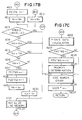
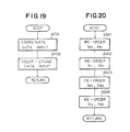
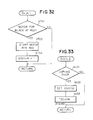
- Fig. 19 is a flowchart showing the details of the coordinate data input subroutine program AC07 also included in the editing mode control subroutine program AB08 described with reference to Fig. 16.
- the coordinate data input subroutine program AC07 starts with a step AF01 to input the numerical data representative of the x-coordinates X a1 and X b1 and y-coordinates Y c1 and Y d1 to defining the desired edited copy erase area 1 and the x-coordinates X a2 and X b2 and y-coordinates Y c2 and Y d2 to defining the desired edited copy/erase area 2.
- the data indicative of the colors selected for the desired edited copy erase areas 1 and 2 and the outside area and/or the data selecting the erasure of the images in any one or more of these areas are input at a subsequent step AF02.
- Fig. 20 is a flowchart showing the details of a coordinate re-ordering subroutine program AD01 included in the subroutine program AC04 described with reference to Figs. 17A, 17B and 7C.
- this coordinate re-ordering subroutine program AD01 comparison is first made between the two x-coordinates X a1 and X b1 for the desired edited copy/erase area 1 whereby the coordinates X a1 and X b1 are arranged in an increasing order at a step AG01.
- the step AG01 is followed by a step AG02 at which comparison is made between the two y-coordinates Y c1 and Y d1 for the copy/erase area 1 and the coordinates Y c1 and Y d1 are arranged in an increasing order at a step AG02.
- comparison is made between the two x-coordinates X a2 and X b2 for the desired edited copy/erase area 2 whereby the coordinates X a2 and X b2 are arranged in an increasing order at a step AG03.
- Comparison is thereafter made between the two y-coordinates Y c2 and Y d2 for the copy/erase area 2 and the coordinates Y c2 and Y d2 are arranged in an increasing order at a step AG04.
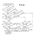
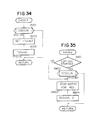
- Fig. 21 is a flowchart showing the details of an eraser control buffer line memory initialize subroutine program AD21 included in the subroutine program AC04 described with reference to Figs. 17A, 17B and 17C or the subroutine program AC05 described with reference to Figs. 18A and 18B.
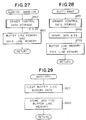
- the eraser control buffer line memory initialize subroutine program AD21 starts with a decision step AH01 at which is questioned whether or not a single-cycle two-colored mode of copying operation is currently requested. If the answer for this step AH01 is given in the negative, it is further queried at a step AH02 whether or not the developing unit 58 b assumed to be storing black-colored toner particles is selected for use in the current cycle of copying operation.
- step AH02 If the answer for this step AH02 is given in the affirmative, then it is confirmed at a step AH03 whether or not the black print color is currently selected for the outside area surrounding the areas 1 and 2. If the answer for the step AH03 is also given in the affirmative, a control data is generated at a step AH04 to produce an instruction to turn off all the light emitter elements 252 of the charge eraser unit 98.
- step AH05 If it is found at the step AH01 that a single-cycle two-colored mode of copying operation is currently selected, it is further queried at a step AH05 whether or not it is requested to erase the images within the outside area. If the answer for this step AH05 is given in the affirmative, a control data is generated at a step AH06 to produce an instruction to turn on all the light emitter elements 252 of the charge eraser unit 98. On the other hand, if it is found at the step AH02 that the developing unit 58 b is not selected for use in the current cycle of copying operation, then it is confirmed at a step AH07 whether or not the red print color is currently selected for the outside area surrounding the areas 1 and 2.
- step AH07 If the answer for the step AH07 is given in the affirmative or if the answer for the step AH05 is given in the negative, a control data is generated at a step AH08 to produce an instruction to turn off all the light emitter elements 252 of the charge eraser unit 98. If the answer for the step AH03 or the step AH07 is given in the negative, the step AH06 is also followed to produce an instruction to turn on all the light emitter elements 252 of the charge eraser unit 98.
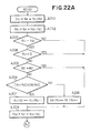
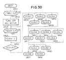
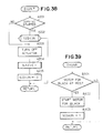
- Figs. 22A and 228 are flowcharts showing the details of the y-axis data calculation subroutine program AD22 included in the subroutine program AC04 described with reference to Figs. 17A, 17B and 17C.
- the charge eraser unit 98 used in the copying apparatus embodying the present invention is typically composed of sixty light emitter elements 252 each of an LED.
- the resolution to be achieved by the eraser unit 98 is dictated by the width of each of such light emitter elements 252 or. in other words, by the pitch distances at which the light emitter elements 252 are arranged in an array.
- the width of the specified edited copy/erase area 1 or 2 in the direction of y-axis or the width of the area to be reproduced with a magnification ratio less than 1:1 is less than the width of the unit element 252 of the the eraser unit 98, it is necessary to secure at least a single light emitter element 252 for the reproduction of the area with such a width because the particular area might otherwise be extincted with all the light emitted elements 252 of the unit 98 activated. Consideration to avoid such an inconvenience is also paid in the y-axis data calculation subroutine program subroutine program AD22.
- a decision step AJ03 it is then confirmed at a decision step AJ03 whether or not y-coordinate Y c1 is equal to the y-coordinate Y d1 . If it is found that that the y-coordinates Y c1 and Y d1 are not equal to each other, it is tested at a step AJ04 whether or not the value of the smaller y-coordinate Y c1 is zero. If it is found that this is not the case, it is further tested at a step AJ05 whether or not the value of the larger y-coordinate Y d1 is 60 (which corresponds to the number of the light emitter elements 252 of the eraser unit 98).
- step AJ06 compares the value Y c1 (N) with the fraction rounded up and the value Y d1 (N) with the fraction rounded down. If it is found at this step AJ06 that the former is larger than the latter, the value Y c1 (N) with the fraction rounded up is decremented by one at a step AJ07. If it is found at the step AJ06 that the value Y c1 (N) with the fraction rounded up is equal to or less that the Y d1 (N) with the fraction rounded down, the value Y d1 (N) with the fraction rounded down is incremented by one at a step AJ08.
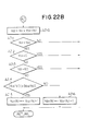
- a decision step AJ11 determines whether or not y-coordinate Y c2 is equal to the y-coordinate Y d2 . If it is found that that the y-coordinates Y c2 and Y d2 are not equal to each other, it is tested at a step AJ12 whether or not the value of the smaller y-coordinate Y c2 is zero. If it is found that this is not the case, it is further tested at a step AJ13 whether or not the value of the larger y-coordinate Y d2 is 60.
- step AJ14 compares the value Y c2 (N) with the fraction rounded up and the value Y d2 (N) with the fraction rounded down. If it is found at this step AJ14 that the former is larger than the latter, the value Y c2 (N) with the fraction rounded up is decremented by one at a step AJ15. If it is found at the step AJ06 that the value Y c2 -(N) with the fraction rounded up is equal to or less that the value Y d2 (N) with the fraction rounded down, the value Y d2 (N) with the fraction rounded down is incremented by one at a step AJ16.
- step AJ07 or AJ08 and the step AJ15 or AJ16 are intended to make a correction for the larger one of the number resulting from the y-coordinate Y c1 or Y c2 with the fraction rounded up and the number resulting from the y-coordinate Y d1 or Y d2 with the fraction rounded down.
- Such a correction results in elimination or reduction in any deviation between the specified edited copy erase area "1" or 2 and the corresponding coverage of the light emitter elements 252 of the eraser unit 98.
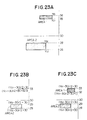
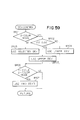
- FIGs. 23A, 23B and 23C are shown edited copy erase areas 1 and 2 to be reproduced in an anamorphic mode of copying operation with certain magnification ratios in the directions of x-axis and y-axis, wherein the vertical axis indicates the direction of y-axis of a copying sheet and thus corresponds to the direction in which the light emitter elements 252 of the charge eraser unit 98 are arranged in an array
- the numerals shown along the vertical axis are graduations respectively representative of some of the light emitter elements 252 of the eraser unit 98 as counted from one end of the -linear array of the elements 252.
- the light emitter element 252 indicated by the graduation 30 thus corresponds to the element located at the center point of the array.
- the copy/erase areas 1 and 2 shown in Fig. 23A are assumed to be reproduced with a magnification ratio of 1:1 selected for each of the directions of x-axis and y-axis.
- the copy/erase area 1 in Fig. 23A is assumed to be reproduced by turning off the light emitter elements 252 represented by those indicated by the graduations 35 and 35 and the copy/erase area 2 assumed to be reproduced by turning off the light emitter elements 252 represented by those indicated by graduations 26 to 28.
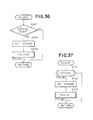
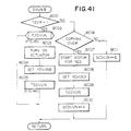
- Fig. 24 is a flowchart showing the details of the priority determination subroutine program further included as the subroutine AD25 in the subroutine program described with reference to Figs. 17A, 17B and 17C or as the subroutine AE18 the subroutine program described with reference to Figs. 18A and 18B.
- This eraser activation data setting subroutine program AD25/AE18 is used to set up the data for the selective activation of the light emitter elements 252 of the charge eraser unit 98 upon judgement of the order of priority between the edited copy/erase areas 1 and 2.
- Such a subroutine program AD25/AE18 starts with a decision step AK01 to determine whether or not the x-coordinate X a1 for one copy/erase area 1 is equal to or less than the x-coordinate X a2 for the other copy erase area 2. If it is found that that the x-coordinate X a1 is equal to or less than the x-coordinate X a2 , it is further tested at a step AK02 to determine whether or not the x-coordinate X b1 for one copy erase area 1 is equal to or larger than the x-coordinate Xb2 for the other copy erase area 2.
- step AK03 If it is found that that the x-coordinate X b1 is equal to or less than the x-coordinate X b2 . then it is tested at a step AK03 whether or not the y-coordinate Y c1 for one copy erase area 1 is equal to or less than the y-coordinate Y c2 for the other copy/erase area 2. If it is found that that the x-coordinate Y c1 is equal to or less than the x-coordinate Y c2 , it is further tested at a step AK04 to determine whether or not the y-coordinate Y d1 for one copy/erase area 1 is equal to or larger than the y-coordinate Y d2 for the other copy/erase area 2.
- the copy/erase area 2 is contained in its entirety within the copy/erase area 1. If the answer for any of the steps AK01 to AK04 is given in the negative, it is determined that the copy/erase area 2 has at least a portion located outside the copyerase area 1.
- control data are generated by one control data generating subroutine program AK05 for the selective activation of the light emitter elements 252 of the charge eraser unit 98 to reproduce the images within the copy/erase area 1 and, thereafter, control data are generated by another control data generating subroutine program AK06 for the selective activation of the light emitter elements 252 to reproduce the images within the copy/erase area 2.
- control data are generated by a subroutine program AK07 for the selective activation of the light emitter elements 252 of the eraser unit 98 to reproduce the images within the copy/erase area 2 and, thereafter, control data are generated by a subroutine program AK08 for the selective activation of the light emitter elements 252 to reproduce the images within the copy/erase area 1.
- copying conditions specified for the copy/erase area 1 are in principle accepted preferentially over those specified for the copy/erase area 2 except when the copy erase area 2 is totally contained within the copy/erase area 1 the copy/erase area 2.
- the copy erase areas 1 and 2 may be specified to be partly overlapped by each other as shown in Fig. 11A, wherein the area 1 is assumed to be requested to be printed in black and the area 2 assumed to be requested ed to be printed in red with the images in the outside area requested to be totally erased.
- the images within the area 1 including the portion overlapped by the area 2 will be all printed in black and the images within the portion of the area 2 outside the area 1 will be printed in red.
- the area 2 is specified to be totally contained within the area 1 as shown in Fig. 12. only that portion of the copy/erase area 1 which surrounds the copy/erase area 2 will be printed in black and the copy/erase area 2 will be printed in red.
- each of the control data generating subroutine programs AK05 and AK07 included in the priority determination subroutine program AD25 starts with a decision step AL01 to confirm whether or not the instruction flag FEDTWD has a logic "1" bit state effective to update the data for the selective activation of the light emitter elements 252 of the eraser unit 98. If it is found that that the flag has a logic "1" bit state, it is tested at a subsequent step AL02 whether or not a single-cycle two-colored mode of copying operation is currently requested.
- step AL03 If the answer for this step AL02 is given in the negative, it is further queried at a step AL03 whether or not the lower developing unit 58 b assumed to be storing black-colored toner particles is selected for use in the current cycle of copying operation. If the answer for this step AL03 is given in the affirmative, then it is confirmed at a step AL04 whether or not the black print color is currently selected for the area 1. If the answer for the step AL04 is also given in the affirmative, a control data is generated by a subroutine program AL05 to produce an instruction to turn off all the light emitter elements 252 of the charge eraser unit 98.
- step AL02 If it is found at the step AL02 that a single-cycle two-colored mode of copying operation is currently selected. it is further queried at a step AL06 whether or not it is requested to erase the images within the area 1. If the answer for this step AL06 is given in the affirmative, a control data is generated by a subroutine program AL07 to produce an instruction to turn on all the light emitter elements 252 of the charge eraser unit 98. On the other hand, if it is found at the step AL03 the developing unit 58b is not selected for use in the current cycle of copying operation, then it is confirmed at a step AL08 whether or not the red print color is currently selected for the area 1.
- a data is prepared by a subroutine program AL09 to generate an instruction to turn off all the light emitter elements 252 of the charge eraser unit 98. If the answer for the step AL04 or the step AL08 is given in the negative, the subroutine program AL07 is also followed to produce an instruction to turn on all the light emitter elements 252 of the charge eraser unit 98.
- each of the control data generating subroutine programs AK06 and AK08 included in the priority determination subroutine program AD25 comprises steps and subroutine programs AM01 to AM09. These steps and subroutine programs AM01 to AM09 are similar to those of the subroutine program AK05/AK07 described with reference to Fig. 25 and are used for controlling the activation of the charge eraser unit 98 in respect of the area 2.
- Fig. 27 is a flowchart showing the details of an eraser control subroutine program which corresponds to the eraser control subroutine program AL05 or AL09 included in the subroutine program AK05/AK07 described with reference to Fig. 25 and the eraser control subroutine program AM05 or AM09 included in the subroutine program AK06/AK08 described with reference to Fig. 26.
- the eraser control subroutine program AL05/AL09/AM05 AM09 includes an eraser control data storage subroutine program AN01 for storing eraser control data into the buffer line memory provided to control the activation of the charge eraser unit 98.
- the eraser control data storage subroutine program AN01 is followed by a step AN02 at which a logic "AND" operation is performed to combine the data stored in the buffer line memory and the data stored in a main line memory (not shown).
- a logic "AND" operation is performed to combine the data stored in the buffer line memory and the data stored in a main line memory (not shown).
- the details of the eraser control data storage subroutine program AN01 will be described with reference to Fig. 29.
- Fig. 28 is a flowchart showing the details of an eraser control subroutine program which corresponds to the eraser control subroutine program AL07 included in the subroutine program AK05/AK07 described with reference to Fig. 25 and the subroutine program AM07 included in the eraser control subroutine program AK06/AK08 described with reference to Fig. 26.
- the eraser control subroutine program AL07/AM07 includes an eraser control data storage subroutine program AP01 for storing eraser control data into the buffer line memory as in the subroutine program AN01 of the eraser control subroutine program AL05/AL09/AM05/AM09 described with reference to Fig. 27.
- the eraser control data storage subroutine program AP01 is followed by a step AP02 at which the bits of the data stored into the buffer line memory are logically inverted. Subsequently to the step AP02, a logic "OR" operation is performed to combine the data thus inverted and the data stored in the main line memory.
- the details of the eraser control data storage subroutine program AP01 will also be desribed with reference to Fig. 29.
- the eraser control data storage subroutine program AN01/AP01 includes a step AQ01 to clear the data stored in the eraser control buffer line memory.
- the step AQ01 is followed by a step AQ02 at which data formulated in accordance with which the eraser unit 98 is to be controlled for operation are stored into the buffer line memory.
- Fig. 30 is a flowchart showing the developing stage control subroutine program AB07 included in the main routine program to be executed by the second CPU2 302.
- the subroutine program AB07 is executed to control the image developing stage 58 in accordance with the instruction and data signals received from the control panel 200 directly or through the master CPU1 300. More specifically, the subroutine program AB07 is executed to control the drive motor 60 (M D ) provided for the image developing stage 58 and the solenoid-operated actuator 140 provided for each of the developing units 58 a and 58 b of the stage 58.
- the motor 60 is provided to drive the rotatable members 116, 118 and 120 forming part of each of the developing units 58 a and 58 b for applying toner particles to the peripheral surface of the image transfer drum 54 from a selected one of the developing units 58 a and 58 b .
- the solenoid-operated actuator 140 provided in association with the magnetic rotor 130 of each of the developing units 58 a and 58 b of the stage 58.
- the magnetic rotor 130 is biased to be held in the inoperative angular position having the magnet members S 1 and N 1 equally spaced apart from the gap D s and is, when actuated, forced to turn to the operative angular position having the magnet member N 1 located close to the gap D s as shown in Fig. 3.
- the developing stage control subroutine program AB07 starts with a decision step AR01 at which it is questioned whether or not the time which may have been counted by a timer TMDEV1 has lapsed.
- the timer TMDEV1 is predominant over the time at which the motor 60 for driving the rotatable members 116, 118 and 120 of the lower developing unit 58 b is to be brought to a stop.
- an instruction signal is issued at a step AR02 to bring the motor 60 to a stop.
- the step AR02 is followed by a step AR03 at which it is tested whether or not the time which may have been counted by a timer TMDEVR has lapsed.
- the timer TMDEVR is predominant over the period of time for controlling the area over which images are to be developed on the image transfer drum 54.
- a flag FDVR is shifted to a logic "0" bit state at a step AR04.
- the flag FDVR is used to dictate the timing at which the program predominant over a single-cycle two-colored mode of copying operation is to be executed and shifts to a logic "1" bit state when the leading end of the document sheet which is on the point of being scanned by the document scanner 36 is detected by a timing sensor (not shown) provided in conjunction with the scanner 36.
- the flag FDVR is shifted to a logic "0" bit state when the trailing end of the area of the latent images on the peripheral surface of the image transfer drum 54 is passed through the gap Ds between the drum 54 and the applicator sleeve 120 of the lower developing unit 58b.
- the step AR04 is followed by a step AR05 at which a status code SCDVUN is checked for the numerical value currently represented by the code.
- the status code SCDVUN is expressed in the hexadecimal notation and may thus indicate any of the numerical values 0 to E (which equals 14 in the decimal notation.
- the step AR05 is followed by any one of subroutine programs AR06, AR07, AR08, ... AR19 and AR20 which are respectively labeled as DVUN0.
- the subroutine program AR06 (labeled as DVUN0) is to be executed at an initial stage of the control process
- the subroutine programs AR07 to AR10 (respectively labeled as DVUN1 to DVUN4) are to be executed to select red as the color to be used for printing
- the subroutine programs AR11 to AR13 (respectively labeled as DVUN5 to DVUN7) are to be executed to select black as the color to be used for printing
- the subroutine programs AR14 to AR20 (respectively labeled as DVUN8 to DVUNE) are to be executed to control a single-cycle two-colored mode of copying operation.
- the details of the initial control subroutine program AR06 (DVUN0) will be described with reference to Fig. 31.
- the details the red select subroutine programs AR07 to AR10 (DVUN1 to DVUN4) will be described with reference to Figs. 32 to 35.
- the details of the black select subroutine programs AR11 to AR13 (DVUN5 to DVUN7) will be described with reference to Figs. 36 to 38.
- the details of the single-cycle two-colored mode subroutine programs AR14 to AR20 (DVUN8 to DVUNE) will be described with reference to Figs. 39 to 44.
- Fig. 31 is a flowchart showing the details of the initial control subroutine program AR06 (DVUN0) included in the subroutine program AB07 illustrated in Fig 30
- the initial control subroutine program AR06 starts with a decision step AS01 to check whether or not a copying operation is currently in progess. If the answer for this step AS01 is given in the affirmative, it is further queried at a subsequent step AS02 whether or not the main charger 56 is in operation. If the answer for this step AS02 is also given in the affirmative. it is tested at a step AS03 whether or not a single-cycle two-colored mode of copying operation is currently requested.
- step AS04 it is queried at a step AS04 whether or not the lower developing unit 58 b assumed to be storing black-colored toner particles is selected for use in the current cycle of copying operation. If it is found that that the developing unit 58 b is selected for use, then at a step AS05 the status code SCDVUN is changed to have a numerical value 5 calling for the execution of the subroutine program AR11 (DVUNS) and an instruction signal is issued at a step AS06 to energize the solenoid-operated actuator 140 for the developing unit 58 b .
- DVDUNS subroutine program AR11
- An instruction signal is then issued at a step AS07 to energize the motor 60 for the developing unit 58 b so that the developing operation is performed with use of the developing unit 58 b storing black-colored toner particles.
- the timer TMDV1 predominant of the timing at which the motor 60 for the developing unit 58 b is to be de-energized is reset at a step AS08. If it is found that at the step AS04 that the developing unit 58 b is not currently selected for use, then at a step AS10 the status code SCDVUN is changed to have a numerical value 1 calling for the execution of the subroutine program AR08 (DVUN2) and a color flag FDVCLR is shifted to a logic "1" state at a step AS10.
- the color flag FDVCLR of logic "1" slat is effective to change the print color from red to black or make a shift from the developing unit 58 a to the developing unit 58 b . If, on the other hand, it is found at the step AS03 that there currently is a request for a single-cycle two-colored mode of copying operation, then at a step AS11 the status code SCDVUN is changed to have a numerical value 8 calling for the execution of the subroutine program AR14 (DVUN8). Subsequently to the step AS10 or the step AS11, a subroutine program SLEEVE1 for the control of the lower developing unit 58 b storing the black-colored toner particles is executed at a step AS12 as will be described with reference to Fig. 47.
- Figs. 32 to 35 are flowcharts showing the details of red select subroutine programs AR07 to AR10 (DVUN1 to DVUN4) included in the subroutine program AB07 illustrated in Fig 30.
- the subroutine program AR07 includes a step AT01 to check if the motor 60 for the lower developing unit 58 b storing black-colored toner particles remains de-energized. If it is found that that the motor 60 for the developing unit 58 b remains de-energized, an instruction signal is issued at a step AT02 to start the motor 60 for the upper developing unit 58 a storing red-colored toner particles and. thereafter, the status code SCDVUN is incremented by one at a step AT03 to have a numerical value 2 calling for the execution of the subroutine program AR08 (DVUN2).
- the subroutine program AR08 includes a step AU01 to confirm whether or not the preceding copying operation is terminated.
- a data YDVUN2 is formulated at a step AU02 and a subroutine program TSDVUN to set data on a timer TMDVUN for the control of the developing stage 58 is thereafter executed at a step AU03.
- the details of this subroutine program TSDVUN will be described with reference to Fig. 46
- the subroutine program AR09 includes a step AV01 to execute a subroutine program TJDVUN for processing data for the timer TMDVUN for the control of the developing stage 58.
- the details of the subroutine program TJDVUN will be described with reference to Fig. 45.
- the step AV01 is followed by a step AV02 at which a data YDVUN3 is generated at a step AV02 and the subroutine program TSDVUN is thereafter executed at a step AV03 as will be described with reference to Fig. 46.
- the subroutine program AR10 includes a decision step AW01 to confirm whether or not the copying operation to be performed in the next has been started. If it is found that that such copying operation has not been started, the subroutine program TJDVUN is executed at a step AW02. as will be described with reference to Fig. 45.
- an instruction signal is issued at a step AW03 to de-energize the motor 60 for the upper developing unit 58a storing red-colored toner particles.
- the status code SCDVUN is at a step AW04 shifted to have a numerical value 0 calling for the execution of the subroutine program AR06 (DVUN0).
- Figs. 36 to 38 are flowcharts showing the details of black select subroutine programs AR11 to AR13 (DVUN5 to DVUN7) included in the subroutine program AB07 illustrated in Fig 30.
- the subroutine program AR11 includes a step AX01 to confirm whether or not the preceding copying operation is terminated.
- a data YDVUN5 is formulated at a step AX02 and the subroutine program TSDVUN is thereafter executed at a step AX03.
- the details of this subroutine program TSDVUN will be described with reference to Fig. 46.
- the subroutine program AR12 includes a step AY01 to execute the subroutine program TJDVUN for processing data for the timer TMDVUN for the control of the developing stage 58, as will be described with reference to Fig. 45.
- the subroutine program AY01 is followed by a step AY02 at which a data YDVUN6 is generated and the subroutine program TSDVUN is thereafter executed at a step AY03 as will be described with reference to Fig. 46.
- the subroutine program AR13 includes a decision step AZ01 to confirm whether or not the copying operation to be performed in the next has been started. If it is found that that such copying operation has not been started, the subroutine program TJDVUN is executed at a step AZ02, as will be described with reference to Fig. 45.
- an instruction signal is issued at a step AZ03 to de-energize the solenoid-operated actuator 140 for the lower developing unit 58 b storing black-colored toner particles to bring an end to the developing operation using the lower developing unit 58 b .
- the subroutine program SLEEVE1 for the control of the lower developing unit 58 b is executed at a step AS12, as will be described with reference to Fig. 47.
- the status code SCDVUN is at a step AZ04 shifted to have a numerical value 0 calling for the execution of the subroutine program AR06 (DVUN0).
- Figs. 39 to 44 are flowcharts showing the details of single-cycle two-colored mode control subroutine programs AR14 to AR20 (DVUN8 to DVUNE) included in the subroutine program AB07 illustrated in Fig 30.
- the subroutine program AR14 includes a decision step BA01 to check if the motor 60 for the lower developing unit 58 b storing black-colored toner particles remains de-energized. If it is found that that the motor 60 for the developing unit 58 b remains de-energized.
- an instruction signal is issued at a step BA02 to start the motor 60 for the upper developing unit 58 a storing red-colored toner particles and thereafter, the status code SCDVUN is incremented by one at a step BA03 to have a numerical value 9 calling for the execution of the subroutine program AR15 (DVUN9). If it is found at the step BA01 that the motor 60 for the lower developing unit 58 b is in operation, the subroutine program AR14 is repeated until the motor 60 for the developing unit 58 b is de-energized.
- the subroutine programs AR15 and AR16 includes a decision step BB01 to query whether or not the flag FDVR to dictate the timing to control the single-cycle two-colored mode of copying operation has a logic "1" bit state. If the answer for this step BB01 is given in the affirmative, it is tested at a step BB02 whether or not there is present an output signal S BL of a logic "1" bit from the boundary detector 106 responsive to interception of light by the light interceptor element 104. As noted previously, the signal SBL of a logic "1" bit is representative of the location of the boundary line defined between desired zones of a copying sheet which are to be printed in different colors.
- step BB02 If it it found at the step BB02 that there is present such a signalS BL ,the previously mentioned data YDVUN9 is at a step BB03 formulated and set on the timer TMDVUN for the control of the developing stage 58 and a subroutine program TSDVUN is thereafter executed at a step BB04 as will be described with reference to Fig. 46.
- step BB05 If it is found at the step BB01 that the flag FDVR has a logic "0" bit state, it is confirmed at a step BB05 whether or not the preceding copying operation is terminated.
- a data YDVUN3 is at a step BB06 formulated and set on the timer TMDVUN for the control of the developing stage 58 and the subroutine program TSDVUN is thereafter executed at a step BB07 as will be described with refrence to Fig. 46.
- the status code SCDVUN is shifted at a step BB08 to a numerical value 4 calling for the execution of the subroutine program AR10 (DVUN4). If it is found at the step BB05 that the preceding copying operation is terminated. then the status code SCDVUN is shifted at a step BB09 to a numerical value E calling for the execution of the subroutine program AR20 (DVUNE).
- the subroutine program AR16 includes a step BB10 to check if the flag FDVR to dictate the timing to control the single-cycle two-colored mode of copying operation has a logic "1" bit state. If the answer for this step BB10 is given in the affirmative, the subroutine program TJDVUN is executed at a step B11 for processing data for the timer TMDVUN for the control of the developing stage 58, as will be described with reference to Fig. 45. An instruction signal is then issued at a step BB12 to de-energize the motor 60 for the upper developing unit 58 a storing the red-colored toner particles.
- step BB12 is followed by a step BB13 at which a data YDVUNA is generated and the subroutine program TSDVUN is thereafter executed at a step BB14 as will be described with reference to Fig. 46. If it is found at the step BB10 that the flag FDVR has a logic "0" bit state, the step BB10 is followed by the decision step BB05.
- the subroutine program AR17 includes a decision step BC01 to confirm whether or not the flag FDVR to dictate the timing to control the single-cycle two-colored mode of copying operation has a logic "1" bit state. If the answer for this step BC01 is given in the affirmative, the subroutine program TJDVUN is executed at a step BC02 for processing data for the timer TMDVUN for the control of the developing stage 58, as will be described with reference to Fig. 45. An instruction signal is then issued at a step BC03 to energize the solenoid-operated actuator 140 for the lower developing unit 58 b storing the black-colored toner particles.
- step BC03 is followed by a step BC04 at which a data YDVUNB is generated and the subroutine program TSDVUN is thereafter executed at a step BC05 as will be described with refrence to Fig. 46. If it is found at the step BC01 that the flag FDVR has a logic "0" bit state, the step BC01 is followed by a decision step BC06 at which it is confirmed whether or not the preceding copying operation is terminated. When termination of the preceding copying operation is confirmed at this step BC06, an instruction signal is issued at a step BC07 to energize the motor 60 for the upper developing unit 58 a storing the red-colored toner particles.
- the step BC07 is followed by a step BC08 at which a data YDVUN3 is formulated and set on the timer TMDVUN for the control of the developing stage 58 and the subroutine program TSDVUN is thereafter executed at a step BC09 as will be described with refrence to Fig. 46.
- the status code SCDVUN is shifted at a step BC10 to a numerical value 4 calling for the execution of the subroutine program AR10 (DVUN4). If it is found at the step BC06 that the preceding copying operation is terminated, then the status code SCDVUN is shifted at a step BC11 to a numerical value E calling for the execution of the subroutine program AR20 (DVUNE).
- the subroutine program AR18 includes a decision step BD01 to confirm whether or not the flag FDVR to dictate the timing to control the single-cycle two-colored mode of copying operation has a logic "1" bit state. If the answer for this step BD01 is given in the affirmative, the subroutine program TJDVUN is executed at a step BD02 for processing data for the timer TMDVUN for the control of the developing stage 58, as will be described with reference to Fig. 45. An instruction signal is then issued at a step BD03 to energize the motor 60 for the lower developing unit 58 b storing the black-colored toner particles.
- the status code SCDVUN is shifted at a step BD07 to a numerical value 0 calling for the execution of the subroutine program AR06 (DVUN0). If it is found at the step BD06 that the preceding copying operation is terminated. then the status code SCDVUN is shifted at a step BD08 to a numerical value E calling for the execution of the subroutine program AR20 (DVUNE).
- the subroutine program AR19 includes a decision step BE01 to query whether or not the flag FDVR to dictate the timing to control the single-cycle two-colored mode of copying operation has a logic "0" bit state. If the answer for this step BE01 is given in the affirmative. it is confirmed at a step BE02 whether or not the preceding copying operation is terminated. When termination of the preceding copying operation is confirmed at this step BE02, a data YDVUN6 is at a step BE03 formulated and set on the timer TMDVUN for the control of the developing stage 58 and the subroutine program TSDVUN is thereafter executed at a step BE04 as will be described with refrence to Fig. 46. Thereafter.
- the status code SCDVUN is shifted at a step BE05 to a numerical value 7 calling for the execution of the subroutine program AR13 (DVUN7). If it is found at the step BE02 that the preceding copying operation is terminated, an instruction signal is issued at a step BE06 to de-energize the solenoid-operated actuator 140 for the lower developing unit 58 b storing the black-colored toner particles. The step BE06 is followed by a step BE07 to execute the subroutine program SLEEVE1 for the control of the lower developing unit 58 b . as will be described with reference to Fig. 47. Then, the status code SCDVUN is shifted at a step BE08 to a numerical value E calling for the execution of the subroutine program AR20 (DVUNE).
- the subroutine program AR20 includes a decision step BF01 at which it is confirmed whether or not the preceding copying operation is terminated.
- the status code SCDVUN is shifted at a step BF02 to a numerical value 0 calling for the execution of the subroutine program AR06 (DVUN0). If it is found at the step BF01 that the preceding copying operation is terminated, it is queried at a step BF03 whether or not the flag FDVR to dictate the timing to control the single-cycle two-colored mode of copying operation has a logic "1" bit state.
- step BF04 If the answer for this step BF03 is given in the affirmative, an instruction signal is issued at a step BF04 to energize the motor 60 for the upper developing unit 58 a storing the red-colored toner particles.
- the step BF04 is followed by a step BF05 at which the status code SCDVUN is shifted to a numerical value 9 calling for the execution of the subroutine program AR15 (DVUN9).
- Fig. 45 is a flowchart showing the details of the subroutine program TJDVUN included in each of the subroutine programs DVUN3 (Fig. 34), DVUN4 (Fig. 35), DVUN6 (Fig. 37), DVUN7 (Fig. 38). DVUNA (Fig 40), DVUNB (Fig. 41) and DVUNC (Fig. 42).
- the subroutine program TJDVUN is used for the processing of data for the timer TMDVUN for the control of the developing stage 58 and includes a decision step BG01 to chek if there currently is a request for activation of the timer TMDVUN.
- an instruction signal is issued at a step BG02 to increment the timer TMDVUN by one.
- the subroutine program TJDVUN proceeds to the subsequent step and, if not, the subroutine program TJDVUN recycles to the step BG01.
- Fig. 46 is a flowchart showing the details of the subroutine program TSDVUN included in each of the subroutine programs DVUN2 (Fig. 33), DVUN3 (Fig. 34), DVUN5 (Fig. 36), DVUN6 (Fig. 37), DVUN9 (Fig. 40), DVUNB (Fig. 41) and DVUND (Fig. 43).
- the subroutine program TSDVUN is used to set data on the timer TMDVUN for the control of the developing stage 58 and includes a step BH01 to set data on the timer TMDVUN and thereafter the status code SCDVUN is incremented by one at a step BH02 to update the control status for the developing stage 58.
- Fig. 47 is a flowchart showing the details of the subroutine program SLEEVE1 included in each of the subroutine programs DVUN0 (Fig. 31), DVUN7 (Fig. 38) and DVUND (Fig. 43).
- the subroutine program SLEEVE1 is used for the control of the lower developing unit 58 b storing the black-colored toner particles and includes a step BJ01 to issue an instruction signal to start the motor 60 for the developing unit 58 b storing the black-colored toner particles.
- the step BJ01 is followed by a step BJ02 at which a data YSLEV1 is set on the timer TMDEV1 is predominant over the time at which the motor 60 for the lower developing unit 58 b is to be brought to a stop.
- Figs. 48 and 49 are timecharts showing the timings at which the developing units 58 a and 58 b are to be made operative and inoperative in the various subroutine programs hereinbefore described with reference to Figs. 30 to 47 when copying operation is performed in two consecutive cycles.
- Fig. 49 shows that the motor 60 for the lower developing unit 58 b is energized simultaneously (with the actuator 140 for the developing unit 58 b maintained de-energized) when the main charger 56 is activated. Simultaneously when the motor 60 for the developing unit 58 b is brought to a stop, the motor 60 for the upper developing unit 58 a is energized.
- the two developing units 58 a and 58 b could not be operative concurrently and, for this reason, the load imposed by the developing stage 58 is maintained below a certain limit value.
- timing for starting the motor 60 for the upper developing unit 58 a is sufficiently earlier than the timing at which the latent images produced on the image transfer drum 54 by means of the document scanner 36 approach the developing unit 58 a .
- the motor 60 for the developing unit 58 a is brought to a stop.
- Fig. 50 is a timechart showing the timings at which the developing units 58 a and 58 b are to be made operative and inoperative during a single-cycle two-colored mode of copying operation.
- the timing at which a shift is made from the upper developing unit 58 a to the lower developing unit 58 b is made under the control of the signal S BL produced by the boundary detector 106 and thus representative of the location of the boundary line defined between desired zones of a copying sheet to be printed in different colors.
- Fig. 51 shows a control panel 400 for use in a second preferred embodiment of an image duplicating apparatus according to the present invention.
- the control panel 400 herein shown is largely similar to its counterpart described with reference to Fig. 5 and thus comprises all the equivalents of the switches and indicators of the control panel 200 shown in Fig. 5. Such equivalents of the switches and indicators are designated by the same reference numerals as those used in Fig. 5.
- the control panel 400 herein shown comprises, in addition to the switches and indicators on the control panel 200, a duplex copy mode select switch 402 and a composite copy mode select switch 404 with respectively associated indicators 402 a and 404 a as shown.
- the copying apparatus embodying the present invention comprises the duplex/composite copy paper feed system 94 which is usually used for producing printed images on the reverse face of the copy sheet which has printed images already produced on its front face.
- the duplex/composite copy paper feed system 94 is also operable for a two-cycle two-colored editing mode of copying operation in which images within one specified area of a copying sheet are to be printed in one color and images within another specified area of the sheet are to be printed in another color on the same side of the sheet on which the images within the former area have been printed.
- a copy sheet which has been passed through the image-fixing and sheet-discharge system 30 may be either discharged to the paper discharge tray 92 or transferred to the duplex/composite copy paper feed system 94 by means of the two-way guide member 96.
- an actuator which when activated drives the two-way guide member 96 to move to a position to direct a copy sheet toward the paper discharge tray 92 and an actuator which when activated drives the two-way guide member 96 to move to a position to transfer a copy sheet to the duplex/composite copy paper feed system 94.
- roller pairs forming part of the duplex/composite copy paper feed system 94 include a roller pair having an associated actuator which when activated drive the roller pair to a position operative to direct a copy sheet to a path leading toward the timing rollers 82 past, for example, the second pair of paper feed rollers 78.
- the duplex/composite copy paper feed system 94 may further comprise a shift assembly operative to pass a copy sheet to the paper feed mechanism 28 with the previously printed side of the sheet directed upwardly for a duplex mode of copying operation or downwardly for a composite or two-cycle two-colored editing mode of copying operation.
- Fig. 52 shows the general arrangement of a control circuit which may be used to carry out the functions achievable from the control panel 400 thus arranged.
- the control circuit comprises a first or master CPU 408 and a second or slave CPU 410 which are coupled together through a bidirectional bus 412.
- the first CPU1 408 is predominant over the various aspects and phases of the copying operation to be carried out by the apparatus except for those the charge eraser unit 98.
- the CPU 408 is thus operative to control not only the ordinary and editing modes of copying operation to be performed by the image reproducing system 26 and paper feed mechanism 28 but also the duplex and composite modes of copying operation.
- the CPU1 408 is thus responsive to various control and data signals which may be supplied from the control panel 400 and dictates the starts and stops of the various drive and actuator units associated with the image reproducing system 26 and paper feed mechanism 28.
- these drive and actuator units are assumed to include a main drive motor (M MD ) for driving the image transfer drum 54 and the various rollers included in the paper feed mechanism 28, a drive motor (M DV ) associated with each of the developing units 58 a and 58 b , a clutch (C TM ) for actuating the timing rollers 82, a clutch (C PF1 ) for actuating the first pair of paper feed rollers 76, a clutch (C PF2 ) for actuating the second pair of paper feed rollers 76.
- M MD main drive motor
- M DV drive motor
- C TM clutch
- C PF1 clutch
- C PF2 for actuating the second pair of paper feed rollers 76.
- the first CPU1 408 is further connected through a decoder 414 to the various indicators on the control panel 400 including the display window 206 and display screen 206 through switch elements 416 as shown.
- the CPU2 410 is predominant over the operation of the light emitter elements 252 of the charge eraser unit 98.
- the CPU2 41 is thus responsive to the control and data signals supplied from the editing copy mode control section 226 of the control panel 400 to control the selective activation of the light emitter elements 252 of the charge eraser unit 98.
- the second CPU2 302 is connected to an eraser control circuit which is similar to its counterpart 312 in the control circuit described with reference to Figs. 8 and 9
- Fig. 53 shows the main routine program to be executed by the first or master CPU1 408 hereinbefore described with reference to Fig. 52.
- the routine program starts with the copying apparatus switched in and initializes the master CPU1 408 at a step BK01 so that all the copying conditions and modes of operation to be controlled by means of the CPU1 408 are selected in accordance with prescribed default rules.
- An internal timer of the system is then initiated at a step BK02 to count the time interval predetermined for a single complete iteration through the routine program.
- the master CPU1 408 may then execute a color select subroutine program BK03 by which one or both of the developing units 58 a and 58 b respectively storing red-colored and black-colored toner particles may be selected for use depending upon an instruction signal or signals entered at the control panel 400.
- the details of the color select subroutine program BK03 will be hereinafter described with reference to Fig. 54.
- the color select subroutine program BK03 may be followed by a single-cycle two-color mode signal processing subroutine program BK04 to process signals entered at the control panel 400 with a single-cycle two-color mode of copying operation selected
- the details of the subroutine program BK04 will be hereinafter described with reference to Fig. 55.
- the master CPU1 408 may thereafter execute a duplex/composite mode select subroutine program BK05 by which either a duplex mode of copying operation or a composite mode of copying operation is selected depending upon an an instruction signal or signals entered at the control panel 400.
- a duplex/composite mode select subroutine program BK05 by which either a duplex mode of copying operation or a composite mode of copying operation is selected depending upon an an instruction signal or signals entered at the control panel 400.
- the details of the duplex/composite mode select subroutine program BK05 will be hereinafter described with reference to Fig. 56.
- the master CPU1 300 may then execute an editing copy mode setup subroutine program BK06 to set up conditions establishing an editing mode of copying operation and thereupon may further execute a copying operation control subroutine program BK07 predominant over the copying operation to be performed by the apparatus in accordance with the various instruction and data signals supplied from the control panel 400.
- the details of the editing copy mode setup subroutine program BK06 will be hereinafter described with reference to Fig. 57 and the details of the copying operation control subroutine program BK07 described with reference to Figs. 58A. 58B and 58C.
- the master CPU1 408 may further execute a develop stage control subroutine program BK08 for controlling the developing operation to be performed by one or both of the developing units 58 a and 58 b .
- the details of the develop stage control subroutine program BK08 will be hereinafter described with reference to Fig. 59.
- Further executed by the master CPU1 408 is a miscellaneous job subroutine program BK09 including inter-CPU communication for communicating with the slave CPU2 410.
- the system Upon lapse of the predetermined time interval as detected at a step BK10 after the internal timer of the system has been initiated at the step BK02, the system reverts to the step BK02 and recycles the subroutine programs BK02 to BK09.
- Fig. 54 is a flowchart showing the details of the color select subroutine program BK03 included in the main routine program illustrated in Fig. 53.
- the color select subroutine program BK03 starts with a decision step BL01 at which it is queried whether or not there is present a signal produced with the color select switch 220 depressed on the control panel 200. In the presence of such a signal, it is further confirmed at a step BL02 whether or not the upper developing unit 58 a has been selected until the signal was produced with the switch 220 depressed.
- step BL03 If the answer for this step BL02 is given in the affirmative, an instruction signal is issued at a step BL03 so that the lower developing unit 58 b storing the black-colored toner particles is selected for use and accordingly the indicator 220 a allocated to the black print color is turned on to illuminate.
- step BL04 If, conversely, the answer for the step BL02 is given in the negative, an instruction signal is issued at a step BL04 so that the upper developing unit 58 a storing the red-colored toner particles is selected for use and accordingly the indicator 220 a allocated to the red print color is turned on to illuminate Subsequently to the step BL03 or the step BL04 or in the absence of a signal produced with the color select switch 220 depressed as found at the step BL01, it is queried at a step BL05 whether or not the two indicators 220 a allocated to the black and red print colors are turned on with the editing copy mode select switch 230 depressed in the editing copy mode control section 226 of the control panel 400. If it is found that such two indicators 220 a are turned on, both of the upper and lower developing units 58 a and 58 b storing the red-colored and black-colored toner particles are selected for use with the two indicators 220 a turned on.
- Fig. 55 is a flowchart showing the details of the single-cycle two-color mode signal processing subroutine program BK04 included in the main routine program illustrated in Fig. 53.
- the single-cycle two-color mode signal processing subroutine program BK04 starts with a decision step BM01 at which it is queried whether or not there is present a signal produced with the single-cycle two-color mode switch 222 depressed. In the presence of such a signal, it is further confirmed at a step BM02 whether or not the indicator 222 a associated with the switch 222 is turned on.
- an instruction signal is issued at a step BM03 to turn off the indicator 222 a and, thereafter, it is queried at a step BM04 whether or not the lower developing unit 58 b has been selected until the single-cycle two-color mode switch 222 is depressed. If the answer for this step BM04 is given in the affirmative. an instruction signal is issued at a step BM05 to turn on one of the indicators 220 a allocated to the black print color and turn off the remaining indicators 220 a associated with the color select switch 220.
- step BM04 If it is found at the step BM04 that the lower developing unit 58 b has been selected until the single-cycle two-color mode switch 222 is depressed, then an instruction signal is issued at a step BM06 to turn off the indicator 220 a allocated to the black print color and turn off the indicator 220 a allocated to the print color of the toner particles stored in the upper developing unit 58 a which is herein assumed as storing red-colored toner particles.
- step BM02 If it is found at the step BM02 that the indicator 222 a associated with the single-cycle two-color mode switch 222 is turned off, an instruction signal is issued at a step BM07 to turn on the indicator 222 a and an instruction signal is issued at a step BM08 to turn on the indicator 220 a allocated to the black print color Thereafter. It is queried at a step BM09 whether or not the lower developing unit 58 b stores red-colored toner particles. The answer for this step BM09 being given in the affirmative, an instruction signal is issued at a step BM10 to turn on the indicator 220 a allocated to the red print color. If, however, the answer for the step BM09 is given in the negative, then an instruction signal is issued at a step BM11 to turn on another one of the indicators 220 a associated with the color select switch 220.
- Fig. 56 is a flowchart showing the details of the duplex composite mode select subroutine program BK05 included in the main routine program illustrated in Fig. 53.
- the duplex composite mode select subroutine program BK05 starts with a decision step BN01 at which it is queried whether or not a copying operation is currently in progress. If the answer for this step BN01 is given in the affirmative, it is further tested at a step BN02 whether or not the indicator 404 a associated with the composite copy mode select switch 404 is turned off. If the indicator 404 a is found to be turned off, it is now questioned at a step BN03 whether or not there is present a signal produced with the duplex copy mode select switch 402 depressed.
- step BN03 it is confirmed at a step BN03 whether or not the indicator 402 a associated with the duplex copy mode select switch 402 is turned on. If the indicator 402 a is found to be turned on, an instruction signal is issued at a step BN05 to turn off the indicator 402 a associated with the switch 402. In the absence of the signal produced with the duplex copy mode select switch 402 depressed. an instruction signal is issued at a step BN06 to turn on the indicator 402 a associated with the switch 402.
- step BN05 or step BN06 if it is found at the step BN02 that the indicator 404 a associated with the composite copy mode select switch 404 is turned on, it is queried at a step BN07 whether or not the indicator 402 a associated with the duplex copy mode select switch 402 is turned off. If the indicator 402 a is found to be turned on, it is now questioned at a step BN08 whether or not there is present a signal produced with the composite copy mode select switch 404 depressed. In the presence of such a signal, it is confirmed at a step BN09 whether or not the indicator 404 a associated with the composite copy mode select switch 404 is turned on.
- an instruction signal is issued at a step BN10 to turn off the indicator 404 a associated with the switch 404.
- an instruction signal is issued at a step BN11 to turn on the indicator 404 a associated with the switch 404.
- step BN12 it is tested at a step BN13 whether or not a single-cycle two-colored mode of copying operation is currently selected in the presence of a signal produced with the single-cycle two-colored mode select switch 222 depressed. If it is found that that the single-cycle two-colored mode of copying operation is selected, then an instruction signal is issued at a step BN14 to turn on the indicator 404 a associated with the switch 404. If the answer for the step BN12 or step BN13 is given in the negative, the duplex composite mode select subroutine program BK05 recycles to the step BN01.
- Fig. 57 is a flowchart showing the details of the editing copy mode setup subroutine program BK06 included in the main routine program illustrated in Fig. 53.
- the editing copy mode setup subroutine program BK06 starts with a decision step BP01 at which it is queried whether or not a single-cycle two-colored mode of copying operation is currently selected in the presence of a signal produced with the single-cycle two-colored mode select switch 222 depressed. In the presence of such a signal, an instruction signal is issued at a step BP02 to turn off all the indicators 220 a associated with the color select switch 220 and enable entry of signals to build up an area in the area display screen 234.
- step BP02 Subsequently to this step BP02 or if it is found at the step BP01 that a single-cycle two-colored mode of copying operation is not currently selected, it is confirmed at a step BP03 whether or not entry of the x-coordinates X a1 and X b1 and y-coordinates Y c1 and Y d1 for the desired edited copy erase area 1 is complete. If the answer for this step BP03 is given in the affirmative, it is further queries at a step BP04 whether or not both of the upper and lower developing units 58 a and 58 b are installed within the apparatus.
- an instruction signal is issued at a step BP05 by which the indicators 246 a , 248 a and 250 a respectively associated with the black select switch 246, area color switch 248 and area erase switch 250 are turned on to flicker. If it is found at the step BP04 that only the lower developing unit 58 b is installed within the apparatus, then an instruction signal is issued at a step BP06 by which the indicators 246 a and 250 a respectively associated with the black select switch 246 and area erase switch 250 are turned on to flicker.
- step BP05 or step BP06 an instruction signal is issued at a step BP07 by which the indicator associated with the depressed one of the switches 246, 248 and 250 is permitted to illuminate continuously.
- an instruction signal is issued at a step BP10 by which the indicators 246 a 248 a and 250 a respectively associated with the black select switch 246, area color switch 248 and area erase switch 250 are turned on to flicker. If it is found at the step BP10 that only the lower developing unit 58 b is installed within the apparatus, then an instruction signal is issued at a step BP11 by which the indicators 246 a and 250 a respectively associated with the black select switch 246 and area erase switch 250 are turned on to flicker.
- step BP10 or step BP11 an instruction signal is thus issued at a step BP12 by which the indicator associated with the depressed one of the switches 246, 248 and 250 is permitted to illuminate continuously.
- Figs. 58A, 588 and 58C are flowcharts showing the details of the copying operation control subroutine program BK07 included in the main routine program illustrated in Fig. 53.
- the copying operation control subroutine program BK07 starts with a decision step BQ01 at which it is tested whether or not the indicator 402 a associated with the duplex copy mode select switch 402 is turned off. If the indicator 402 a is found to be turned off, it is now questioned at a step BQ02 whether or not the indicator 404 a associated with the composite copy mode select switch 404 is turned off. If the indicator 404 a is found to be turned off, it is confirmed at a step BQ03 whether or not there is present a signal produced with the print start switch 202 depressed.
- a print start flag F ps is shifted to a logic "1" bit at a step BQ04. If the indicator 404 a is found to be turned on at the step BQ02, it is further questioned at a step BQ05 whether or not the composite mode of copying operation is ready to be executed. On the other hand, if it is determined at the step BQ01 that the indicator 402 a associated with the duplex copy mode select switch 402 is turned on, it is tested at a step BQ06 whether or not the duplex mode of copying operation is ready to be executed. If the answer for the step BQ05 or the step BQ06 is given in the negative. the subroutine program recycles to the initial step BQ01.
- step BQ07 If the answer for the step BQ05 or BQ06 is given in the affirmative, it is confirmed at a step BQ07 whether or not there is present a signal produced with the print start switch 202 depressed. When it is found that the there is present such a signal, a print start flag F ps is shifted to a logic "1" bit at a step BQ08 and a first copy flag F c1 is shifted to a logic "1" bit at a step BQ09.
- step BQ10 determines whether or not a second copy flag F c2 has a logic "1" bit. If it is found that that the second copy flag F c2 has a logic "1" bit, it is confirmed at a step BQ11 whether or not the supply of a copying sheet for use in a duplex or composite mode of copying operation is complete by the duplex composite copy paper feed system 94.
- step BQ11 If the answer for this step BQ11 is given in the affirmative, then the second copy flag F c2 is shifted to a logic "0" bit at a step BQ12 and the print start flag F ps is shifted to a logic "1" bit at a step BQ13.
- step BQ14 it is confirmed at a step BQ14 whether or not the print start flag F ps is of a logic "1" bit If the answer for this step BQ14 is given in the affirmative. the print start flag F ps is shifted to a logic "0" bit and signals are issued to activate the drivers and actuators for the main drive motor, the motor for each of the developing units 58 a and 58 b , and the chargers 56, 62 and 64.
- step BQ15 are also started internal timers TA and TB of the CPU1 408.
- the timer TA is predominant over the time when each of the clutches for the paper feed rollers 72 and 74 is to be de-energized and the timer TB is predominant over the time at which the document scanning system 24 is to be initiated into motion.
- step BQ15 it is confirmed at a step BQ16 whether or not the second copy flag F c2 has a logic "0" bit. If it is found that the second copy flag F c2 has a logic "0" bit, it is further queried at a step BQ17 or through steps BQ17 and BQ18 which of the first and second paper supply cassettes 70a and 70 b is currently selected.
- a signal is issued at a step BQ19 or a step BQ2 to actuate either the clutch for the first paper feed roller 72 or the clutch for the second paper feed roller 74 to feed a copying sheet from the paper supply cassette 70 a or 70 b If it is found at the step BQ16 that the second copy flag F c2 has a logic "1" bit. then an instruction signal is issued at a step BQ21 to activate the clutch (C RC , Fig 52) for actuating the paper recirculation roller pair included in the duplex/composite copy paper feed system 94.
- step BQ22 it is confirmed at a step BQ22 whether or not the time set by the timer TA is reached.
- a signal is issued at a step BQ23 to de-energize the clutch for the paper feed roller 72 or 74 or the clutch (C RC ) for the paper recirculation roller pair which has been in operation.
- a document scanning signal S SC of a logic "1" bit is issued at a step BQ25 to enable the document scanning system 24 to start the optical scanning operation.
- the subroutine program BK07 then jumps to the steps shown in Fig. 588 and questions at a step whether or not there is a timing signal S TM of a logic "1" bit.
- the timing signal S TM of logic "1" bit is issued when it is detected that the document scanner 36 has reached a predetermined position after the scanner was initiated into forward movement from its home position.
- a signal is issued at a step BQ27 to actuate the clutch (C TM ) for the timing rollers 82 so that the copying sheet which has reached the timing rollers 82 is allowed to advance into contact with the rotating image transfer drum 54.
- step BQ27 is further started an internal timer TC of the CPU1 408.
- the timer TC of the CPU1 408 is predominant over the time at which the scanning operation by the system 24 is to be terminated and the clutch (C TM ) for the timing rollers 82 is to be de-energized.
- the time thus counted by the timer TC is a parameter dictated by the selected size of the copying sheet and the selected magnification ratio of copying.
- a scanner return signal S RT is of a logic "1" bit.
- This scanner return signal S RT is generated when the document scanner 36 reaches the predetermined foremost position with respect to the document table 22. On transition of the scanner return signal S RT to logic "1" bit, the document scanner 36 starts to travel back to its home position. If the current copying operation is of the multi-copying mode requiring to produce two or more copy prints for a single document, it is confirmed at a subsequent step BQ31 whether or not the copying cycles have been repeated the required number of times.
- step BQ32 If it is confirmed that the multi-copying operation is complete, it is further confirmed at a step BQ32 whether or not the first copy flag F c1 is of a logic "1" bit. At a point of time the document scanner 36 reaches its home position and accordingly the first copy flag F c1 is detected to have a logic "1" bit, the first copy flag F c1 is shifted to logic "0" bit at a step BQ33 and the second copy flag F c2 is shifted to logic "1" bit at a step BQ34. It is then confirmed at a step BQ35 whether or not there is present a scanner home position signal S HM of a logic "1" bit which is generated when the document scanner 36 has moved back to its home position.
- step BQ36 signals are issued at a step BQ36 to stop the motor in the developing stage 58 and de-activate the transfer charger 62.
- step BQ36 is further started an internal timer TD which is predominant over the time when the main drive motor is to be brought to a stop. If it is found at the step BQ31 that the multi-copying operation is still incomplete, then the print start flag F ps is shifted to a logic "1" bit at a step BQ37 to complete the required multi-copying operation.
- Fig. 59 is a flowchart showing the details of the developing stage control subroutine program BK08 included in the main routine program illustrated in Fig. 53.
- the developing stage control subroutine program BK08 starts with a decision step BR01 at which it is queried whether or not a two-colored copy mode of operation is currently selected in the presence of a signal produced with the editing copy mode select switch 230 depressed. In the presence of such a signal. it is confirmed at a step BR02 whether or not the duplicate images are to be printed on a first side of the supplied copying sheet. If the answer for this step BR02 is given in the affirmative, an instruction signal is issued at a step BR03 to select for use the upper developing unit 58 a storing the red-colored toner particles.
- step BR02 If the answer for this step BR02 is given in the negative, viz., the duplicate images are to be printed on a second side of the supplied copying sheet.
- an instruction signal is issued at a step BR04 to select the lower developing unit 58 b storing the black-colored toner particles. If it is found at the step BR01 that a two-colored copy mode of operation is not currently selected, then an instruction signal is issued at a step BR05 so that the selected one of the developing units 58 a and 58 b is to be put to use. Subsequently to any of the steps BR03, BR04 and BR05, it is queried at a step BR06 whether or not a single-cycle two-colored mode of copying operation is selected with the switch 222 depressed.
- the instruction signal issued at any of the steps BR03, BR04 and BR05 is disregarded and instead an instruction signal is issued at a step BR07 to use both of the upper and lower developing units 58 a and 58 b respectively for the two separate zones defined by the color shift control device 100.
Landscapes
- Physics & Mathematics (AREA)
- General Physics & Mathematics (AREA)
- Engineering & Computer Science (AREA)
- Microelectronics & Electronic Packaging (AREA)
- Human Computer Interaction (AREA)
- Control Or Security For Electrophotography (AREA)
- Color Electrophotography (AREA)
Claims (2)
- Bildvervielfältigungsgerät mit:(a) Mitteln (204, 224, 242), um nacheinander und in der Reihenfolge erste und zweite örtlich festgelegte Flächen (AREA1, AREA2) eines Dokumentblattes zu bestimmen, das ein sichtbares Bild trägt, wobei die Bestimmungsmittel angepaßt sind, um die Bestimmung der Flächen in dem Fall zu ermöglichen, in dem die zweite Fläche vollständig von der ersten Fläche umgeben ist;(b) Eingabemitteln (246, 248, 250), um Kopierbedingungen bezüglich der Ausbildung von Bildern, die innerhalb der ersten Fläche (AREA1), innerhalb der zweiten Fläche (AREA2) bzw. außerhalb der ersten und der zweiten Fläche (OUTSIDE) liegen, einzugeben; und(c) Bildreproduziermitteln, um selektiv die so bestimmten Flächen auf dem Dokument auf ein einzelnes Kopierblatt zu verdoppeln, nämlichvon der ersten Fläche des Dokuments in Übereinstimmung mit der Bedingung bezüglich der ersten örtlich festgelegten Fläche;von der zweiten Fläche des Dokuments in Übereinstimmung mit der Bedingung bezüglich der zweiten örtlich festgelegten Fläche; undvon der Fläche außerhalb der ersten und der zweiten Fläche des Dokuments in Übereinstimmung mit der Bedingung bezüglich der Außenseite der ersten und der zweiten örtlich festgelegten Fläche;(d) Mitteln, die von der Reihenfolge, in der die erste und die zweite Fläche durch die Bestimmungsmittel bestimmt wurden, abhängig sind, um festzulegen, ob die zweite Fläche vollständig innerhalb der ersten Fläche liegt;(e) Mitteln, die von den Bestimmungsmitteln abhängig sind, um der zweiten Fläche Priorität zu geben, wenn diese vollständig innerhalb der ersten Fläche ist, so daß die Bildreproduziermittel die Bilder der gesamten Fläche des Dokuments auf einer einzelnen Seite eines Kopierblattes verdoppeln, nämlichundvon der zweiten Fläche des Dokuments in Übereinstimmung mit der Kopierbedingung bezüglich der zweiten Fläche;von der Fläche innerhalb der ersten Fläche und außerhalb der zweiten Fläche des Dokuments in Übereinstimmung mit der Kopierbedingung bezüglich der ersten Fläche; undvon der Fläche außerhalb der ersten Fläche des Dokuments in Übereinstimmung mit der Bedingung bezüglich der Außenseite der ersten und der zweiten Fläche;(f) Mitteln, die von den Bestimmungsmitteln abhängig sind, um der Kopierbedingung, die für die erste Fläche festgelegt ist, Priorität über die Kopierbedingung, die für die zweite Fläche festgelegt ist, zu geben, wenn die zweite Fläche nicht vollständig innerhalb der ersten Fläche ist, so daß die überlappenden Teile der zweiten und der ersten Fläche in Übereinstimmung mit der Kopierbedingung verdoppelt werden, die der ersten Fläche zugeordnet ist;(g) wobei die durch das Eingabemittel einzugebenden Kopierbedingungen drei verschiedene Kopierbetriebmodi enthalten.
- Bildvervielfältigungsgerät nach Anspruch 1,
bei der die drei verschiedenen Kopierbetriebsmodi einen Betriebsmodus zum Löschen der Bilder innerhalb einer festgelegten Fläche des Dokumentblattes enthalten.
Applications Claiming Priority (14)
| Application Number | Priority Date | Filing Date | Title |
|---|---|---|---|
| JP13309187 | 1987-05-28 | ||
| JP133091/87 | 1987-05-28 | ||
| JP143552/87 | 1987-06-08 | ||
| JP14355587A JPS63306471A (ja) | 1987-06-08 | 1987-06-08 | 複写機 |
| JP143555/87 | 1987-06-08 | ||
| JP143556/87 | 1987-06-08 | ||
| JP62143552A JPS63306469A (ja) | 1987-06-08 | 1987-06-08 | 複写機 |
| JP143554/87 | 1987-06-08 | ||
| JP62143556A JPS63306472A (ja) | 1987-06-08 | 1987-06-08 | 複写機 |
| JP143551/87 | 1987-06-08 | ||
| JP62143554A JPS63306481A (ja) | 1987-06-08 | 1987-06-08 | 複写機 |
| JP143553/87 | 1987-06-08 | ||
| JP62143553A JP2733923B2 (ja) | 1987-06-08 | 1987-06-08 | 複写機 |
| JP62143551A JPS63306465A (ja) | 1987-06-08 | 1987-06-08 | 複写機 |
Publications (3)
| Publication Number | Publication Date |
|---|---|
| EP0293543A1 EP0293543A1 (de) | 1988-12-07 |
| EP0293543B1 EP0293543B1 (de) | 1991-07-03 |
| EP0293543B2 true EP0293543B2 (de) | 1998-12-30 |
Family
ID=27566008
Family Applications (2)
| Application Number | Title | Priority Date | Filing Date |
|---|---|---|---|
| EP88100066A Expired - Lifetime EP0293543B2 (de) | 1987-05-28 | 1988-01-05 | Bildvervielfältigungsgerät |
| EP88100067A Expired EP0292634B1 (de) | 1987-05-28 | 1988-01-05 | Bildvervielfältigungsgerät |
Family Applications After (1)
| Application Number | Title | Priority Date | Filing Date |
|---|---|---|---|
| EP88100067A Expired EP0292634B1 (de) | 1987-05-28 | 1988-01-05 | Bildvervielfältigungsgerät |
Country Status (3)
| Country | Link |
|---|---|
| US (1) | US5083162A (de) |
| EP (2) | EP0293543B2 (de) |
| DE (2) | DE3863491D1 (de) |
Families Citing this family (6)
| Publication number | Priority date | Publication date | Assignee | Title |
|---|---|---|---|---|
| US4901100A (en) * | 1988-08-18 | 1990-02-13 | Xerox Corporation | Single pass color highlighting copying system |
| JP2866153B2 (ja) * | 1990-05-22 | 1999-03-08 | キヤノン株式会社 | 文字処理装置及び方法 |
| JP3374996B2 (ja) * | 1993-11-12 | 2003-02-10 | 理想科学工業株式会社 | 印刷画像位置表示装置 |
| WO2004019274A1 (ja) * | 2002-08-20 | 2004-03-04 | Fuji Xerox Co., Ltd. | 画像形成装置及びその方法 |
| US7564600B2 (en) * | 2004-03-05 | 2009-07-21 | Kabushiki Kaisha Toshiba | Image reading apparatus |
| JP6424858B2 (ja) * | 2016-03-31 | 2018-11-21 | 京セラドキュメントソリューションズ株式会社 | 画像形成装置 |
Family Cites Families (28)
| Publication number | Priority date | Publication date | Assignee | Title |
|---|---|---|---|---|
| US3914043A (en) * | 1974-03-29 | 1975-10-21 | Xerox Corp | Color accenting copying machine |
| JPS5748860A (en) * | 1980-09-08 | 1982-03-20 | Canon Inc | Picture synthesizer |
| DE3238509A1 (de) * | 1981-10-19 | 1983-05-05 | Canon K.K., Tokyo | Bildaufzeichnungsgeraet |
| US4794421A (en) * | 1983-05-12 | 1988-12-27 | Eastman Kodak Company | Apparatus and method for electrophotographically producing copies from originals having continuous-tone and other content |
| JPS60166970A (ja) * | 1984-02-09 | 1985-08-30 | Matsushita Electric Ind Co Ltd | 電子写真装置 |
| JPS60166969A (ja) * | 1984-02-09 | 1985-08-30 | Matsushita Electric Ind Co Ltd | 電子写真装置 |
| JPS60227242A (ja) * | 1984-04-25 | 1985-11-12 | Minolta Camera Co Ltd | 複写機 |
| JPS60237469A (ja) * | 1984-05-10 | 1985-11-26 | Ricoh Co Ltd | 画像形成装置 |
| US4627707A (en) * | 1984-06-16 | 1986-12-09 | Ricoh Company, Ltd. | Copier with image editing function |
| JPS6170564A (ja) * | 1984-09-14 | 1986-04-11 | Toshiba Corp | 画像形成装置 |
| DE3601122A1 (de) * | 1985-01-18 | 1986-07-24 | Kabushiki Kaisha Toshiba, Kawasaki, Kanagawa | Bilderzeugungsgeraet mit bereichswahl und -bestaetigung |
| US4701044A (en) * | 1985-01-29 | 1987-10-20 | Konishiroku Photo Ind. Co., Ltd. | Image recording apparatus for composing plural partial original images into a single composite image |
| GB2173665B (en) * | 1985-02-21 | 1989-07-19 | Canon Kk | Copying apparatus |
| DE3605472C2 (de) * | 1985-02-21 | 1995-05-11 | Canon Kk | Elektrofotografisches Kopiergerät |
| JPS61203474A (ja) * | 1985-03-06 | 1986-09-09 | Canon Inc | カラ−画像形成装置 |
| US4763165A (en) * | 1985-03-18 | 1988-08-09 | Kabushiki Kaisha Toshiba | Image forming apparatus with image adding function |
| US4740810A (en) * | 1985-07-09 | 1988-04-26 | Minolta Camera Kabushiki Kaisha | Copying apparatus |
| JPS6211875A (ja) * | 1985-07-09 | 1987-01-20 | Minolta Camera Co Ltd | 電子写真複写機 |
| JPS6238446A (ja) * | 1985-08-13 | 1987-02-19 | Minolta Camera Co Ltd | 走査型変倍結像装置 |
| JPS6285265A (ja) * | 1985-10-09 | 1987-04-18 | Konishiroku Photo Ind Co Ltd | 静電記録装置 |
| US4766404A (en) * | 1985-11-18 | 1988-08-23 | Canon Kabushiki Kaisha | Coordinate input apparatus |
| DE3639351C2 (de) * | 1985-11-18 | 1994-04-14 | Canon Kk | Kopiergerät |
| US4791450A (en) * | 1985-12-16 | 1988-12-13 | Eastman Kodak Company | Multicolor electrophotographic reproduction apparatus and method for producing color accented copies |
| JPS62172381A (ja) * | 1986-01-24 | 1987-07-29 | Minolta Camera Co Ltd | 編集機能を有する電子写真複写機 |
| JPS6323180A (ja) * | 1986-07-05 | 1988-01-30 | Minolta Camera Co Ltd | 編集機能付作像装置 |
| JPH083691B2 (ja) * | 1986-11-28 | 1996-01-17 | 三田工業株式会社 | 画像形成装置における編集領域設定装置 |
| US4885609A (en) * | 1986-12-01 | 1989-12-05 | Minolta Camera Kabushiki Kaisha | Automatic image duplicating apparatus |
| US4924264A (en) * | 1987-06-30 | 1990-05-08 | Minolta Camera Kabushiki Kaisha | Image duplicating apparatus having edited copying mode |
-
1988
- 1988-01-05 DE DE8888100066T patent/DE3863491D1/de not_active Expired - Lifetime
- 1988-01-05 EP EP88100066A patent/EP0293543B2/de not_active Expired - Lifetime
- 1988-01-05 DE DE8888100067T patent/DE3863488D1/de not_active Expired - Fee Related
- 1988-01-05 EP EP88100067A patent/EP0292634B1/de not_active Expired
-
1989
- 1989-10-03 US US07/418,719 patent/US5083162A/en not_active Expired - Lifetime
Also Published As
| Publication number | Publication date |
|---|---|
| DE3863491D1 (de) | 1991-08-08 |
| EP0293543A1 (de) | 1988-12-07 |
| US5083162A (en) | 1992-01-21 |
| DE3863488D1 (de) | 1991-08-08 |
| EP0292634A1 (de) | 1988-11-30 |
| EP0292634B1 (de) | 1991-07-03 |
| EP0293543B1 (de) | 1991-07-03 |
Similar Documents
| Publication | Publication Date | Title |
|---|---|---|
| US4582417A (en) | Apparatus for forming images | |
| US4794421A (en) | Apparatus and method for electrophotographically producing copies from originals having continuous-tone and other content | |
| GB2167046A (en) | Storing sheets during overlay printing | |
| JPH0157786B2 (de) | ||
| US4742372A (en) | Toner detection method and device for copying machines | |
| US4253760A (en) | Electrophotographic apparatus for printing multiple copies of an image on a photosensitive member | |
| EP0293543B2 (de) | Bildvervielfältigungsgerät | |
| US4845525A (en) | Image forming apparatus for forming special information upon copying a document image | |
| JPS58184955A (ja) | 複写機の不要像消去装置 | |
| US4215931A (en) | Electrophotographic apparatus | |
| US4949124A (en) | Image forming apparatus having plural developing units and an arrangement for selecting the developing unit having the highest use count | |
| US5386270A (en) | Electrostatographic reproduction apparatus with annotation function | |
| JP3083140B2 (ja) | 複写装置 | |
| JP2664053B2 (ja) | 電子写真複写機 | |
| EP0255543B1 (de) | Elektrophotographisches vervielfältigungsgerät und verfahren mit selektiver rasterung | |
| JPS6225770A (ja) | 複写装置 | |
| JP2529550B2 (ja) | 2色画像形成装置 | |
| EP0276855A2 (de) | Bildvervielfältigungsapparat | |
| JPS61183670A (ja) | 編集機能付複写装置 | |
| JPH01263671A (ja) | プリンター | |
| JPS61241769A (ja) | プリント付加複写装置 | |
| JPS6310173A (ja) | 電子写真複写機 | |
| JPS6235387A (ja) | 複写装置 | |
| JPS63183467A (ja) | 複写装置 | |
| JPS6235380A (ja) | 複写装置 |
Legal Events
| Date | Code | Title | Description |
|---|---|---|---|
| PUAI | Public reference made under article 153(3) epc to a published international application that has entered the european phase |
Free format text: ORIGINAL CODE: 0009012 |
|
| AK | Designated contracting states |
Kind code of ref document: A1 Designated state(s): DE FR GB |
|
| 17P | Request for examination filed |
Effective date: 19890529 |
|
| 17Q | First examination report despatched |
Effective date: 19891024 |
|
| GRAA | (expected) grant |
Free format text: ORIGINAL CODE: 0009210 |
|
| AK | Designated contracting states |
Kind code of ref document: B1 Designated state(s): DE FR GB |
|
| REF | Corresponds to: |
Ref document number: 3863491 Country of ref document: DE Date of ref document: 19910808 |
|
| ET | Fr: translation filed | ||
| PLBI | Opposition filed |
Free format text: ORIGINAL CODE: 0009260 |
|
| 26 | Opposition filed |
Opponent name: AVABRIDGE LIMITED Effective date: 19920402 |
|
| APAC | Appeal dossier modified |
Free format text: ORIGINAL CODE: EPIDOS NOAPO |
|
| APAC | Appeal dossier modified |
Free format text: ORIGINAL CODE: EPIDOS NOAPO |
|
| RAP2 | Party data changed (patent owner data changed or rights of a patent transferred) |
Owner name: MINOLTA CO., LTD. |
|
| REG | Reference to a national code |
Ref country code: FR Ref legal event code: CD |
|
| APAC | Appeal dossier modified |
Free format text: ORIGINAL CODE: EPIDOS NOAPO |
|
| PLAW | Interlocutory decision in opposition |
Free format text: ORIGINAL CODE: EPIDOS IDOP |
|
| PUAH | Patent maintained in amended form |
Free format text: ORIGINAL CODE: 0009272 |
|
| STAA | Information on the status of an ep patent application or granted ep patent |
Free format text: STATUS: PATENT MAINTAINED AS AMENDED |
|
| 27A | Patent maintained in amended form |
Effective date: 19981230 |
|
| AK | Designated contracting states |
Kind code of ref document: B2 Designated state(s): DE FR GB |
|
| ET3 | Fr: translation filed ** decision concerning opposition | ||
| REG | Reference to a national code |
Ref country code: GB Ref legal event code: IF02 |
|
| APAH | Appeal reference modified |
Free format text: ORIGINAL CODE: EPIDOSCREFNO |
|
| PGFP | Annual fee paid to national office [announced via postgrant information from national office to epo] |
Ref country code: DE Payment date: 20061229 Year of fee payment: 20 |
|
| PGFP | Annual fee paid to national office [announced via postgrant information from national office to epo] |
Ref country code: GB Payment date: 20070103 Year of fee payment: 20 |
|
| REG | Reference to a national code |
Ref country code: GB Ref legal event code: PE20 |
|
| PGFP | Annual fee paid to national office [announced via postgrant information from national office to epo] |
Ref country code: FR Payment date: 20070109 Year of fee payment: 20 |
|
| PG25 | Lapsed in a contracting state [announced via postgrant information from national office to epo] |
Ref country code: GB Free format text: LAPSE BECAUSE OF EXPIRATION OF PROTECTION Effective date: 20080104 |