EP0293518B1 - Teleskopierbares Staubsauger-Saugrohr - Google Patents
Teleskopierbares Staubsauger-Saugrohr Download PDFInfo
- Publication number
- EP0293518B1 EP0293518B1 EP87119407A EP87119407A EP0293518B1 EP 0293518 B1 EP0293518 B1 EP 0293518B1 EP 87119407 A EP87119407 A EP 87119407A EP 87119407 A EP87119407 A EP 87119407A EP 0293518 B1 EP0293518 B1 EP 0293518B1
- Authority
- EP
- European Patent Office
- Prior art keywords
- locking
- vacuum cleaner
- tube
- cleaner suction
- axial
- Prior art date
- Legal status (The legal status is an assumption and is not a legal conclusion. Google has not performed a legal analysis and makes no representation as to the accuracy of the status listed.)
- Expired - Lifetime
Links
- 229920003023 plastic Polymers 0.000 claims description 5
- 239000004033 plastic Substances 0.000 claims description 5
- 230000001154 acute effect Effects 0.000 claims description 4
- 238000007789 sealing Methods 0.000 claims description 2
- 239000000463 material Substances 0.000 claims 2
- 238000004519 manufacturing process Methods 0.000 abstract description 3
- 230000002401 inhibitory effect Effects 0.000 description 4
- 230000006835 compression Effects 0.000 description 2
- 238000007906 compression Methods 0.000 description 2
- 238000010276 construction Methods 0.000 description 2
- 238000005096 rolling process Methods 0.000 description 2
- 229910000831 Steel Inorganic materials 0.000 description 1
- 238000004026 adhesive bonding Methods 0.000 description 1
- 239000011324 bead Substances 0.000 description 1
- 238000012790 confirmation Methods 0.000 description 1
- 238000004049 embossing Methods 0.000 description 1
- 238000005516 engineering process Methods 0.000 description 1
- 238000000034 method Methods 0.000 description 1
- 230000000717 retained effect Effects 0.000 description 1
- 239000010959 steel Substances 0.000 description 1
Images
Classifications
-
- A—HUMAN NECESSITIES
- A47—FURNITURE; DOMESTIC ARTICLES OR APPLIANCES; COFFEE MILLS; SPICE MILLS; SUCTION CLEANERS IN GENERAL
- A47L—DOMESTIC WASHING OR CLEANING; SUCTION CLEANERS IN GENERAL
- A47L9/00—Details or accessories of suction cleaners, e.g. mechanical means for controlling the suction or for effecting pulsating action; Storing devices specially adapted to suction cleaners or parts thereof; Carrying-vehicles specially adapted for suction cleaners
- A47L9/24—Hoses or pipes; Hose or pipe couplings
- A47L9/242—Hose or pipe couplings
- A47L9/244—Hose or pipe couplings for telescopic or extensible hoses or pipes
Definitions
- the invention relates to a telescopic vacuum cleaner suction pipe, as has become known according to the preamble of claim 1 by US-A-3 351 363.
- the outer tube (item 18) known from US-A-3 351 363 (see there Fig. 13-16) has a sleeve-like widening (item 81) at the end, which accommodates an annular plastic sealing body (item. 80), to which an axial rib (item 83) is also assigned (but not integrally formed), which interacts with an axial longitudinal groove (item 28a).
- the anti-rotation device created in this way is required for circumferential centering so that the axial locking adjustment (item 26, 44) remains in overlap and can thus function.
- the sleeve-like widening (item 81) according to US-A-3 351 363 offers advantages in terms of production technology and is insensitive to transverse forces Telescopic connection in particular in the event that the sleeve-like widening constitutes an integral integral part of the outer tube (item 18).
- the handling area of the known design is felt to be too voluminous.
- the invention is based on the object of further improving the known vacuum cleaner suction pipe while maintaining its manufacturing and operating advantages and its stable construction, and in doing so to make it particularly simple further develop compact design. This object is achieved in accordance with the characterizing part of patent claim 1.
- the vacuum cleaner suction pipe according to the invention allows a simple, compact design because practically all the essential functional parts are arranged within the sleeve-like widening.
- a voluminous control panel cf. US-A-3 351 363, Fig. 13, item 82
- the invention can be used with a Satisfy the recess of the sleeve-shaped widening, the comprehensive operating approach.
- This operating approach only needs to be supplemented by a small handle.
- the circular cylindrical plastic ring body also takes over the guiding of the hold-down device or the locking slide.
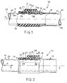
- a telescopic vacuum cleaner suction tube is generally designated by the reference number 10.
- the suction pipe has an inner pipe 11 and an outer tube 12.
- the outer tube 12 forms a sleeve-like widening 13.
- a guide body 15 made of plastic with an essentially circular cross section is arranged inside the overall space designated by 14 between the inner tube outer jacket surface 34 and the outer tube inner jacket surface 33.
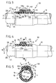
- a guide body 15 Received in the guide body 15 is in each case a slide 16 (FIGS. 1 and 2,) 16a, (FIG. 3) which is translationally movable along the pipe longitudinal axis x (FIG. 3) and a slide 16b which is rotatable about the pipe longitudinal axis x along the circumferential direction u (FIGS. 4 and 5 ).
- Each slide 16, 16a, 16b passes through the outer tube wall 13 with an actuation projection 17 within a recess 18.
- Each actuation projection 17 in turn carries a handle 19.
- Each inner tube 11 has a locking bar 20 with locking recesses 21.
- the inner tube 11 and outer tube 12 are made of sheet steel.
- the locking bar 20 with the locking recesses 21 is stamped into the inner tube wall 22 as a relatively narrow strip-like strip.
- the embossing is in this case such that each latching recess 21 is distanced from the respectively adjacent latching recess 21 via an undeformed circular cylindrical tube wall region 23.
- Each recess 21 has an axial end side which is inclined at an acute angle to the longitudinal axis of the tube x extending sliding flank 24 for a roller-like locking body 25 (FIGS. 1 and 2), for a web-like locking body 25a (FIG. 3) or for a ball locking body 25b (FIGS. 4 and 5).
- each locking recess 21 On the other axial end side of each locking recess 21, a locking or inhibiting flank 26 is formed with a relatively small radius of curvature.
- each latching recess 21 on its axial end side facing the suction attachment (the suction attachment is not shown, but indicated with an S and an arrow), such as a suction brush or suction nozzle, has the curved locking or inhibiting flank 26.
- the respective longitudinal axes of the latching recesses 21 (FIGS. 1-3) intended for elongated latching bodies 25, 25a extend secantially to the body of the inner tube 11, the cross section of which is circular-cylindrical.
- the latching recesses 21 corresponding to FIGS. 4 and 5 are, at least in cross section according to FIG. 5, essentially spherical in shape, while the associated latching body 25b itself - as already mentioned - has a spherical shape.
- the slider 16, 16a, 16b opens the connection to the free space 14, so that the latching body 25, 25a, 25b is able to slide out of the latching recess 21 (ie to decouple the two telescopic tubes 11, 12) as soon as a relative movement of the two telescopic tubes 11, 12 to one another is initiated.
- the latching body 25, 25a, 25b has a relatively small mass, so that a smooth-running latching process, that is to say also a smooth movement of the two tubes 11, 12 with respect to one another, is ensured.
- roller-shaped latching body 25 is located in a latching recess 21 and is held down there by means of a locking lug 27 of the slide 16.
- the locking or inhibiting flanks 26 serve, on the one hand, for a latching mark that can be felt or heard during the adjustment movement and, on the other hand, offer additional securing of the locking position (FIGS. 1, 3 to 5) also in the event that the pressure force in the direction d ( strong impact of the suction attachment S against an obstacle during suction work) should be relatively large. It is also the case in the exemplary embodiment according to FIG. 1 that when a relatively large force occurs in the direction d, an initial rolling movement of the roller body 25 causes a movement of the locking lug 27 in the direction z or g, that is to say an additional securing of the locking position. In this respect, the roller body 25 has approximately the function of a pinion rolling between two racks.
- each latching body 25, 25a, 25b is carried along or positioned approximately in the manner of a ball cage by means of an opening 29 on the slide side.
- the function is similar to that in the exemplary embodiment according to FIGS. 1 and 2.
- the web-like latching body 25a is part of a rectangular bracket or frame made of wire, designated overall by 30.
- the transverse web 31 of the bracket 30 facing away from the locking web 25a is accommodated within an elongated hole 32 on the slide side. It is conceivable that the elongated hole 32 allows the slide 16a to be displaced in the direction o, so that the locking lug 27 can establish the access of the latching body 25a to the free space 14 in order to release the locking state, as shown in FIG. 3.
- FIGS. 4 and 5 The function of the embodiment according to FIGS. 4 and 5 is fundamentally comparable to the embodiments according to FIGS. 1 to 3, with the difference that the actuation of the slide 16b is not translatory in the direction of the longitudinal pipe thing x, but rather rotatory about the longitudinal pipe axis x around in accordance with the arrows in Fig. 5 o in the opening direction and g in the closing direction. Also in this embodiment (Fig. 5) a locking lug 27 can be seen.
- the arrangement 16, 16a, 16b, 25, 25a, 25b could be replaced by a ball catch known per se.
- the handle 19 could be retained or even omitted.
- the strength of the detent force would have to be varied by the restoring force of a ball detent spring, not shown, which would represent the hold-down device in this case.
- the bracket 30 could be guided with its two longitudinal legs within the free space 14 between the outer tube inner jacket surface 33 and the inner tube outer jacket surface 34 within the guide body 15 and against the restoring force of one or two springs (hold-down device), not shown, can be disengaged from the latching recesses 21.
- the latching body 25a and the correlating latching recesses 21 would not be arranged at the top — as shown in FIG. 3 — but rather diametrically opposite on the lower side of the inner tube 11.
- the bead-like axial groove 35 would then - not as shown in Fig. 3 - provided below, but rather diametrically opposite at the top.
- An anti-rotation device between the inner tube 11 and outer tube 12 comes about as follows: The on Outer tube 12 within the widening 13 in a manner not shown in more detail (for example by gluing), rotationally secured guide body 15 engages (see FIG. 5) with an axial spring 36 in the axial longitudinal bead 35 provided on the inner tube side. At the same time, an air seal generating incorrect air is achieved here.
- the arrangement is otherwise such that the front outer region of the guide body 15 engages over an undeformed tube region 23 when the latching bodies 25, 25a, 25b are located in a latching recess 21.
- the invention also provides for axial groove 35 and latching recesses 21 to be superimposed.
- the spherical locking recesses 21 according to FIGS. 4 and 5 could be embossed in the deepest of an axial groove 35 offset circumferentially by 180 ° (the spring 36 would then also be offset).
Landscapes
- Engineering & Computer Science (AREA)
- Mechanical Engineering (AREA)
- Electric Vacuum Cleaner (AREA)
- Electric Suction Cleaners (AREA)
- Hooks, Suction Cups, And Attachment By Adhesive Means (AREA)
Priority Applications (1)
| Application Number | Priority Date | Filing Date | Title |
|---|---|---|---|
| AT87119407T ATE72743T1 (de) | 1987-06-03 | 1987-12-31 | Teleskopierbares staubsauger-saugrohr. |
Applications Claiming Priority (2)
| Application Number | Priority Date | Filing Date | Title |
|---|---|---|---|
| DE3718578A DE3718578C1 (de) | 1987-06-03 | 1987-06-03 | Teleskopierbares Staubsauger-Saugrohr |
| DE3718578 | 1987-06-03 |
Publications (2)
| Publication Number | Publication Date |
|---|---|
| EP0293518A1 EP0293518A1 (de) | 1988-12-07 |
| EP0293518B1 true EP0293518B1 (de) | 1992-02-26 |
Family
ID=6328954
Family Applications (1)
| Application Number | Title | Priority Date | Filing Date |
|---|---|---|---|
| EP87119407A Expired - Lifetime EP0293518B1 (de) | 1987-06-03 | 1987-12-31 | Teleskopierbares Staubsauger-Saugrohr |
Country Status (5)
| Country | Link |
|---|---|
| EP (1) | EP0293518B1 (enExample) |
| AT (1) | ATE72743T1 (enExample) |
| DE (1) | DE3776902D1 (enExample) |
| ES (1) | ES2030706T3 (enExample) |
| GR (1) | GR3004236T3 (enExample) |
Cited By (1)
| Publication number | Priority date | Publication date | Assignee | Title |
|---|---|---|---|---|
| US11137006B2 (en) | 2016-08-17 | 2021-10-05 | D & M Designs Llc | Collapsible telescoping pole |
Families Citing this family (15)
| Publication number | Priority date | Publication date | Assignee | Title |
|---|---|---|---|---|
| DK0520534T3 (da) * | 1991-06-28 | 1994-10-10 | Omeca Spa | Teleskopisk forlængelse af støvsugere |
| DE19615814C2 (de) * | 1995-04-27 | 1998-01-29 | Zelmer | Teleskopierbares Staubsaugerrohr |
| DE19524290C1 (de) * | 1995-07-06 | 1996-08-14 | Froh Roehren | Teleskopierbares Staubsauger-Saugrohr |
| PL181955B1 (pl) * | 1996-10-28 | 2001-10-31 | Zelmer | Teleskopowa rura ssaca do odkurzacza PL |
| AUPP124098A0 (en) * | 1998-01-07 | 1998-01-29 | Tubalco Manufacturing Pty Ltd | Locking arrangement for telescopically moving tubes |
| WO2000000075A1 (en) * | 1998-06-30 | 2000-01-06 | Daewoo Electronics Co., Ltd. | Telescopable wand assembly of a vacuum cleaner |
| EP1092383B1 (en) | 1999-10-11 | 2008-05-07 | OMEC S.p.A. | Telescopic extension for an electric household appliance |
| CN2401136Y (zh) | 2000-01-12 | 2000-10-18 | 徐为尔 | 吸尘器用的吸尘伸缩管 |
| KR200200566Y1 (ko) * | 2000-03-07 | 2000-10-16 | 은성전자주식회사 | 진공청소기의 흡입관 |
| CN2449639Y (zh) | 2000-09-30 | 2001-09-26 | 徐为尔 | 吸尘器用的伸缩吸尘管 |
| GB0425626D0 (en) * | 2004-11-22 | 2004-12-22 | Hoover Ltd | Wand assemblies for vacuum cleaners |
| CN1799487A (zh) * | 2005-09-16 | 2006-07-12 | 邬永龙 | 吸尘器用伸缩式吸尘管 |
| CN100367902C (zh) * | 2005-10-24 | 2008-02-13 | 徐为尔 | 吸尘器上的伸缩式吸管 |
| DE102006006189B3 (de) * | 2006-02-09 | 2007-06-06 | Wolfgang Hermes | Futter- und Tränkvorrichtung für Haustiere |
| DE102013101911B4 (de) * | 2013-02-26 | 2014-11-06 | Fischer Rohrtechnik Gmbh | Staubsauger-Saugrohr |
Citations (2)
| Publication number | Priority date | Publication date | Assignee | Title |
|---|---|---|---|---|
| US3351363A (en) * | 1964-12-23 | 1967-11-07 | Electrolux Corp | Adjustable length wand |
| US3351359A (en) * | 1964-12-23 | 1967-11-07 | Electrolux Corp | Adjustable length wand |
Family Cites Families (6)
| Publication number | Priority date | Publication date | Assignee | Title |
|---|---|---|---|---|
| FR1263595A (fr) * | 1959-07-20 | 1961-06-09 | Electrische App N En Metaalfab | Raccord d'accouplement |
| US3244437A (en) * | 1964-01-28 | 1966-04-05 | Electrolux Corp | Adjustable length vacuum cleaner wand |
| DE2618065C3 (de) * | 1976-04-24 | 1979-08-02 | Carl Froh Roehrenwerk Gmbh & Co, 5768 Sundern | Muffenlose teleskopierbare Rohrverbindung |
| DE3102898A1 (de) * | 1981-01-29 | 1982-08-26 | Licentia Patent-Verwaltungs-Gmbh, 6000 Frankfurt | Klemmvorrichtung an zwei ineinanderschiebbaren saugrohren |
| US4494270A (en) * | 1983-03-25 | 1985-01-22 | Electrolux Corporation | Vacuum cleaner wand |
| US4577837A (en) * | 1984-07-30 | 1986-03-25 | Marvin Berg | Locking mechanism for extendible telescoping tubular members |
-
1987
- 1987-12-31 EP EP87119407A patent/EP0293518B1/de not_active Expired - Lifetime
- 1987-12-31 AT AT87119407T patent/ATE72743T1/de not_active IP Right Cessation
- 1987-12-31 DE DE8787119407T patent/DE3776902D1/de not_active Expired - Lifetime
- 1987-12-31 ES ES198787119407T patent/ES2030706T3/es not_active Expired - Lifetime
-
1992
- 1992-04-01 GR GR920400608T patent/GR3004236T3/el unknown
Patent Citations (2)
| Publication number | Priority date | Publication date | Assignee | Title |
|---|---|---|---|---|
| US3351363A (en) * | 1964-12-23 | 1967-11-07 | Electrolux Corp | Adjustable length wand |
| US3351359A (en) * | 1964-12-23 | 1967-11-07 | Electrolux Corp | Adjustable length wand |
Cited By (1)
| Publication number | Priority date | Publication date | Assignee | Title |
|---|---|---|---|---|
| US11137006B2 (en) | 2016-08-17 | 2021-10-05 | D & M Designs Llc | Collapsible telescoping pole |
Also Published As
| Publication number | Publication date |
|---|---|
| ATE72743T1 (de) | 1992-03-15 |
| GR3004236T3 (enExample) | 1993-03-31 |
| DE3776902D1 (de) | 1992-04-02 |
| ES2030706T3 (es) | 1992-11-16 |
| EP0293518A1 (de) | 1988-12-07 |
Similar Documents
| Publication | Publication Date | Title |
|---|---|---|
| EP0293518B1 (de) | Teleskopierbares Staubsauger-Saugrohr | |
| EP0858762B1 (de) | Teleskopierbares Staubsauger-Saugrohr | |
| DE69200140T2 (de) | Teleskopierbare Rohrverbindung eines Staubsaugers. | |
| DE2711124C2 (de) | Handpipette | |
| EP1208787B1 (de) | Teleskopierbares Staubsauger-Saugrohr | |
| DE2924707C2 (enExample) | ||
| EP0552481B1 (de) | Teleskopierbares Staubsauger-Saugrohr | |
| DE19924450C1 (de) | Teleskopierbares Staubsauger-Saugrohr | |
| DE69911362T2 (de) | Anordnung zum Verbinden zweier rohrförmiger Elemente | |
| EP0859185B1 (de) | Anordnung zum Verbinden zweier rohrförmiger Elemente | |
| DE3718578C1 (de) | Teleskopierbares Staubsauger-Saugrohr | |
| DE19707041A1 (de) | Schnellverbindevorrichtung | |
| DE3046286A1 (de) | Rastung fuer teleskopierbare fuehrungsstiele | |
| DE68903707T2 (de) | Rollvorhang mit einer bremsvorrichtung mit einer zylindrischen nocke. | |
| EP0859106B1 (de) | Obere und untere Verschlussstellenvorrichtung für Türe mit automatischem Schloss | |
| DE4422171A1 (de) | NOT-AUS-Taster | |
| DE2253732C3 (de) | Vorrichtung zum Verstellen des Ausgangsgliedes eines Bewegungsgetriebes | |
| DE8717941U1 (de) | Teleskopierbares Staubsauger-Saugrohr | |
| DE3701433A1 (de) | Zapflanze mit zapfhahnkopf | |
| DE1760544C3 (de) | TürverschluB für eine mit einer Rundumdichtung versehene Beschickungstür einer Wasch- oder Geschirrspülmaschine | |
| DE10034471B4 (de) | Rammbohrgerät | |
| DE2930840C2 (de) | Endabdichtung eines ein Kabel aufnehmenden Ringraumes | |
| EP0079617A2 (de) | Ablassventil für ein Blutdruckmessgerät | |
| DE2134732C3 (de) | Rohrschnellkupplung | |
| EP1795104B1 (de) | Teleskopisches Staubsauger-Saugrohr mit Verlängerungsschiene des Schiebers |
Legal Events
| Date | Code | Title | Description |
|---|---|---|---|
| PUAI | Public reference made under article 153(3) epc to a published international application that has entered the european phase |
Free format text: ORIGINAL CODE: 0009012 |
|
| 17P | Request for examination filed |
Effective date: 19881010 |
|
| AK | Designated contracting states |
Kind code of ref document: A1 Designated state(s): AT BE CH DE ES FR GB GR IT LI LU NL SE |
|
| 17Q | First examination report despatched |
Effective date: 19900222 |
|
| ITF | It: translation for a ep patent filed | ||
| GRAA | (expected) grant |
Free format text: ORIGINAL CODE: 0009210 |
|
| AK | Designated contracting states |
Kind code of ref document: B1 Designated state(s): AT BE CH DE ES FR GB GR IT LI LU NL SE |
|
| REF | Corresponds to: |
Ref document number: 72743 Country of ref document: AT Date of ref document: 19920315 Kind code of ref document: T |
|
| GBT | Gb: translation of ep patent filed (gb section 77(6)(a)/1977) | ||
| REF | Corresponds to: |
Ref document number: 3776902 Country of ref document: DE Date of ref document: 19920402 |
|
| ET | Fr: translation filed | ||
| REG | Reference to a national code |
Ref country code: ES Ref legal event code: FG2A Ref document number: 2030706 Country of ref document: ES Kind code of ref document: T3 |
|
| PLBI | Opposition filed |
Free format text: ORIGINAL CODE: 0009260 |
|
| REG | Reference to a national code |
Ref country code: GR Ref legal event code: FG4A Free format text: 3004236 |
|
| 26 | Opposition filed |
Opponent name: OMEC S.P.A. Effective date: 19921120 |
|
| NLR1 | Nl: opposition has been filed with the epo |
Opponent name: OMEC S.P.A. |
|
| PLAB | Opposition data, opponent's data or that of the opponent's representative modified |
Free format text: ORIGINAL CODE: 0009299OPPO |
|
| R26 | Opposition filed (corrected) |
Opponent name: OMEC S.P.A. Effective date: 19921120 |
|
| EPTA | Lu: last paid annual fee | ||
| EAL | Se: european patent in force in sweden |
Ref document number: 87119407.2 |
|
| PLBN | Opposition rejected |
Free format text: ORIGINAL CODE: 0009273 |
|
| STAA | Information on the status of an ep patent application or granted ep patent |
Free format text: STATUS: OPPOSITION REJECTED |
|
| 27O | Opposition rejected |
Effective date: 19950227 |
|
| NLR2 | Nl: decision of opposition | ||
| REG | Reference to a national code |
Ref country code: CH Ref legal event code: PFA Free format text: CARL FROH ROEHRENWERK GMBH & CO. TRANSFER- CARL FROH GMBH |
|
| REG | Reference to a national code |
Ref country code: FR Ref legal event code: CD Ref country code: FR Ref legal event code: CJ |
|
| BECN | Be: change of holder's name |
Effective date: 19991027 |
|
| NLT1 | Nl: modifications of names registered in virtue of documents presented to the patent office pursuant to art. 16 a, paragraph 1 |
Owner name: CARL FROH GMBH;CARL FROH GMBH & CO |
|
| REG | Reference to a national code |
Ref country code: ES Ref legal event code: PC2A |
|
| REG | Reference to a national code |
Ref country code: CH Ref legal event code: NV Representative=s name: MOINAS & SAVOYE SA |
|
| REG | Reference to a national code |
Ref country code: CH Ref legal event code: PUE Owner name: CARL FROH GMBH TRANSFER- FROH HOUSE TECH GMBH & CO |
|
| NLT1 | Nl: modifications of names registered in virtue of documents presented to the patent office pursuant to art. 16 a, paragraph 1 |
Owner name: FROH HOUSE TECH GMBH & CO. KG |
|
| REG | Reference to a national code |
Ref country code: ES Ref legal event code: PC2A |
|
| REG | Reference to a national code |
Ref country code: FR Ref legal event code: CA |
|
| REG | Reference to a national code |
Ref country code: GB Ref legal event code: IF02 |
|
| PGFP | Annual fee paid to national office [announced via postgrant information from national office to epo] |
Ref country code: GR Payment date: 20041228 Year of fee payment: 18 |
|
| APAH | Appeal reference modified |
Free format text: ORIGINAL CODE: EPIDOSCREFNO |
|
| REG | Reference to a national code |
Ref country code: GB Ref legal event code: 732E |
|
| REG | Reference to a national code |
Ref country code: CH Ref legal event code: PFA Owner name: CARL FROH GMBH Free format text: FROH HOUSE TECH GMBH & CO. KG#AM LINDHOEVEL 1#59846 SUNDERN (DE) -TRANSFER TO- CARL FROH GMBH#157, HACHENER STRASSE#59846 SUNDERN (DE) |
|
| NLS | Nl: assignments of ep-patents |
Owner name: CARL FROH GMBH Effective date: 20060421 |
|
| REG | Reference to a national code |
Ref country code: ES Ref legal event code: PC2A |
|
| REG | Reference to a national code |
Ref country code: FR Ref legal event code: TP |
|
| PGFP | Annual fee paid to national office [announced via postgrant information from national office to epo] |
Ref country code: GB Payment date: 20061218 Year of fee payment: 20 |
|
| PGFP | Annual fee paid to national office [announced via postgrant information from national office to epo] |
Ref country code: AT Payment date: 20061222 Year of fee payment: 20 |
|
| PGFP | Annual fee paid to national office [announced via postgrant information from national office to epo] |
Ref country code: ES Payment date: 20061226 Year of fee payment: 20 |
|
| PGFP | Annual fee paid to national office [announced via postgrant information from national office to epo] |
Ref country code: NL Payment date: 20061229 Year of fee payment: 20 Ref country code: SE Payment date: 20061229 Year of fee payment: 20 |
|
| PGFP | Annual fee paid to national office [announced via postgrant information from national office to epo] |
Ref country code: IT Payment date: 20061231 Year of fee payment: 20 |
|
| PGFP | Annual fee paid to national office [announced via postgrant information from national office to epo] |
Ref country code: BE Payment date: 20070103 Year of fee payment: 20 |
|
| PGFP | Annual fee paid to national office [announced via postgrant information from national office to epo] |
Ref country code: LU Payment date: 20070110 Year of fee payment: 20 |
|
| PGFP | Annual fee paid to national office [announced via postgrant information from national office to epo] |
Ref country code: CH Payment date: 20070111 Year of fee payment: 20 |
|
| PGFP | Annual fee paid to national office [announced via postgrant information from national office to epo] |
Ref country code: DE Payment date: 20070123 Year of fee payment: 20 |
|
| BE20 | Be: patent expired |
Owner name: CARL *FROH G.M.B.H. Effective date: 20071231 |
|
| REG | Reference to a national code |
Ref country code: GB Ref legal event code: PE20 |
|
| PG25 | Lapsed in a contracting state [announced via postgrant information from national office to epo] |
Ref country code: NL Free format text: LAPSE BECAUSE OF EXPIRATION OF PROTECTION Effective date: 20071231 |
|
| REG | Reference to a national code |
Ref country code: CH Ref legal event code: PL |
|
| NLV7 | Nl: ceased due to reaching the maximum lifetime of a patent |
Effective date: 20071231 |
|
| REG | Reference to a national code |
Ref country code: ES Ref legal event code: FD2A Effective date: 20080102 |
|
| EUG | Se: european patent has lapsed | ||
| PG25 | Lapsed in a contracting state [announced via postgrant information from national office to epo] |
Ref country code: GB Free format text: LAPSE BECAUSE OF EXPIRATION OF PROTECTION Effective date: 20071230 Ref country code: GR Free format text: LAPSE BECAUSE OF NON-PAYMENT OF DUE FEES Effective date: 19920226 Ref country code: ES Free format text: LAPSE BECAUSE OF EXPIRATION OF PROTECTION Effective date: 20080102 |
|
| PGFP | Annual fee paid to national office [announced via postgrant information from national office to epo] |
Ref country code: FR Payment date: 20061227 Year of fee payment: 20 |