EP0293518B1 - Telescopic vacuum cleaner suction hose - Google Patents
Telescopic vacuum cleaner suction hose Download PDFInfo
- Publication number
- EP0293518B1 EP0293518B1 EP87119407A EP87119407A EP0293518B1 EP 0293518 B1 EP0293518 B1 EP 0293518B1 EP 87119407 A EP87119407 A EP 87119407A EP 87119407 A EP87119407 A EP 87119407A EP 0293518 B1 EP0293518 B1 EP 0293518B1
- Authority
- EP
- European Patent Office
- Prior art keywords
- locking
- vacuum cleaner
- tube
- cleaner suction
- axial
- Prior art date
- Legal status (The legal status is an assumption and is not a legal conclusion. Google has not performed a legal analysis and makes no representation as to the accuracy of the status listed.)
- Expired - Lifetime
Links
- 229920003023 plastic Polymers 0.000 claims description 5
- 239000004033 plastic Substances 0.000 claims description 5
- 230000001154 acute effect Effects 0.000 claims description 4
- 238000007789 sealing Methods 0.000 claims description 2
- 239000000463 material Substances 0.000 claims 2
- 238000004519 manufacturing process Methods 0.000 abstract description 3
- 230000002401 inhibitory effect Effects 0.000 description 4
- 230000006835 compression Effects 0.000 description 2
- 238000007906 compression Methods 0.000 description 2
- 238000010276 construction Methods 0.000 description 2
- 238000005096 rolling process Methods 0.000 description 2
- 229910000831 Steel Inorganic materials 0.000 description 1
- 238000004026 adhesive bonding Methods 0.000 description 1
- 239000011324 bead Substances 0.000 description 1
- 238000012790 confirmation Methods 0.000 description 1
- 238000004049 embossing Methods 0.000 description 1
- 238000005516 engineering process Methods 0.000 description 1
- 238000000034 method Methods 0.000 description 1
- 230000000717 retained effect Effects 0.000 description 1
- 239000010959 steel Substances 0.000 description 1
Images
Classifications
-
- A—HUMAN NECESSITIES
- A47—FURNITURE; DOMESTIC ARTICLES OR APPLIANCES; COFFEE MILLS; SPICE MILLS; SUCTION CLEANERS IN GENERAL
- A47L—DOMESTIC WASHING OR CLEANING; SUCTION CLEANERS IN GENERAL
- A47L9/00—Details or accessories of suction cleaners, e.g. mechanical means for controlling the suction or for effecting pulsating action; Storing devices specially adapted to suction cleaners or parts thereof; Carrying-vehicles specially adapted for suction cleaners
- A47L9/24—Hoses or pipes; Hose or pipe couplings
- A47L9/242—Hose or pipe couplings
- A47L9/244—Hose or pipe couplings for telescopic or extensible hoses or pipes
Definitions
- the invention relates to a telescopic vacuum cleaner suction pipe, as has become known according to the preamble of claim 1 by US-A-3 351 363.
- the outer tube (item 18) known from US-A-3 351 363 (see there Fig. 13-16) has a sleeve-like widening (item 81) at the end, which accommodates an annular plastic sealing body (item. 80), to which an axial rib (item 83) is also assigned (but not integrally formed), which interacts with an axial longitudinal groove (item 28a).
- the anti-rotation device created in this way is required for circumferential centering so that the axial locking adjustment (item 26, 44) remains in overlap and can thus function.
- the sleeve-like widening (item 81) according to US-A-3 351 363 offers advantages in terms of production technology and is insensitive to transverse forces Telescopic connection in particular in the event that the sleeve-like widening constitutes an integral integral part of the outer tube (item 18).
- the handling area of the known design is felt to be too voluminous.
- the invention is based on the object of further improving the known vacuum cleaner suction pipe while maintaining its manufacturing and operating advantages and its stable construction, and in doing so to make it particularly simple further develop compact design. This object is achieved in accordance with the characterizing part of patent claim 1.
- the vacuum cleaner suction pipe according to the invention allows a simple, compact design because practically all the essential functional parts are arranged within the sleeve-like widening.
- a voluminous control panel cf. US-A-3 351 363, Fig. 13, item 82
- the invention can be used with a Satisfy the recess of the sleeve-shaped widening, the comprehensive operating approach.
- This operating approach only needs to be supplemented by a small handle.
- the circular cylindrical plastic ring body also takes over the guiding of the hold-down device or the locking slide.
- a telescopic vacuum cleaner suction tube is generally designated by the reference number 10.
- the suction pipe has an inner pipe 11 and an outer tube 12.
- the outer tube 12 forms a sleeve-like widening 13.
- a guide body 15 made of plastic with an essentially circular cross section is arranged inside the overall space designated by 14 between the inner tube outer jacket surface 34 and the outer tube inner jacket surface 33.
- a guide body 15 Received in the guide body 15 is in each case a slide 16 (FIGS. 1 and 2,) 16a, (FIG. 3) which is translationally movable along the pipe longitudinal axis x (FIG. 3) and a slide 16b which is rotatable about the pipe longitudinal axis x along the circumferential direction u (FIGS. 4 and 5 ).
- Each slide 16, 16a, 16b passes through the outer tube wall 13 with an actuation projection 17 within a recess 18.
- Each actuation projection 17 in turn carries a handle 19.
- Each inner tube 11 has a locking bar 20 with locking recesses 21.
- the inner tube 11 and outer tube 12 are made of sheet steel.
- the locking bar 20 with the locking recesses 21 is stamped into the inner tube wall 22 as a relatively narrow strip-like strip.
- the embossing is in this case such that each latching recess 21 is distanced from the respectively adjacent latching recess 21 via an undeformed circular cylindrical tube wall region 23.
- Each recess 21 has an axial end side which is inclined at an acute angle to the longitudinal axis of the tube x extending sliding flank 24 for a roller-like locking body 25 (FIGS. 1 and 2), for a web-like locking body 25a (FIG. 3) or for a ball locking body 25b (FIGS. 4 and 5).
- each locking recess 21 On the other axial end side of each locking recess 21, a locking or inhibiting flank 26 is formed with a relatively small radius of curvature.
- each latching recess 21 on its axial end side facing the suction attachment (the suction attachment is not shown, but indicated with an S and an arrow), such as a suction brush or suction nozzle, has the curved locking or inhibiting flank 26.
- the respective longitudinal axes of the latching recesses 21 (FIGS. 1-3) intended for elongated latching bodies 25, 25a extend secantially to the body of the inner tube 11, the cross section of which is circular-cylindrical.
- the latching recesses 21 corresponding to FIGS. 4 and 5 are, at least in cross section according to FIG. 5, essentially spherical in shape, while the associated latching body 25b itself - as already mentioned - has a spherical shape.
- the slider 16, 16a, 16b opens the connection to the free space 14, so that the latching body 25, 25a, 25b is able to slide out of the latching recess 21 (ie to decouple the two telescopic tubes 11, 12) as soon as a relative movement of the two telescopic tubes 11, 12 to one another is initiated.
- the latching body 25, 25a, 25b has a relatively small mass, so that a smooth-running latching process, that is to say also a smooth movement of the two tubes 11, 12 with respect to one another, is ensured.
- roller-shaped latching body 25 is located in a latching recess 21 and is held down there by means of a locking lug 27 of the slide 16.
- the locking or inhibiting flanks 26 serve, on the one hand, for a latching mark that can be felt or heard during the adjustment movement and, on the other hand, offer additional securing of the locking position (FIGS. 1, 3 to 5) also in the event that the pressure force in the direction d ( strong impact of the suction attachment S against an obstacle during suction work) should be relatively large. It is also the case in the exemplary embodiment according to FIG. 1 that when a relatively large force occurs in the direction d, an initial rolling movement of the roller body 25 causes a movement of the locking lug 27 in the direction z or g, that is to say an additional securing of the locking position. In this respect, the roller body 25 has approximately the function of a pinion rolling between two racks.
- each latching body 25, 25a, 25b is carried along or positioned approximately in the manner of a ball cage by means of an opening 29 on the slide side.
- the function is similar to that in the exemplary embodiment according to FIGS. 1 and 2.
- the web-like latching body 25a is part of a rectangular bracket or frame made of wire, designated overall by 30.
- the transverse web 31 of the bracket 30 facing away from the locking web 25a is accommodated within an elongated hole 32 on the slide side. It is conceivable that the elongated hole 32 allows the slide 16a to be displaced in the direction o, so that the locking lug 27 can establish the access of the latching body 25a to the free space 14 in order to release the locking state, as shown in FIG. 3.
- FIGS. 4 and 5 The function of the embodiment according to FIGS. 4 and 5 is fundamentally comparable to the embodiments according to FIGS. 1 to 3, with the difference that the actuation of the slide 16b is not translatory in the direction of the longitudinal pipe thing x, but rather rotatory about the longitudinal pipe axis x around in accordance with the arrows in Fig. 5 o in the opening direction and g in the closing direction. Also in this embodiment (Fig. 5) a locking lug 27 can be seen.
- the arrangement 16, 16a, 16b, 25, 25a, 25b could be replaced by a ball catch known per se.
- the handle 19 could be retained or even omitted.
- the strength of the detent force would have to be varied by the restoring force of a ball detent spring, not shown, which would represent the hold-down device in this case.
- the bracket 30 could be guided with its two longitudinal legs within the free space 14 between the outer tube inner jacket surface 33 and the inner tube outer jacket surface 34 within the guide body 15 and against the restoring force of one or two springs (hold-down device), not shown, can be disengaged from the latching recesses 21.
- the latching body 25a and the correlating latching recesses 21 would not be arranged at the top — as shown in FIG. 3 — but rather diametrically opposite on the lower side of the inner tube 11.
- the bead-like axial groove 35 would then - not as shown in Fig. 3 - provided below, but rather diametrically opposite at the top.
- An anti-rotation device between the inner tube 11 and outer tube 12 comes about as follows: The on Outer tube 12 within the widening 13 in a manner not shown in more detail (for example by gluing), rotationally secured guide body 15 engages (see FIG. 5) with an axial spring 36 in the axial longitudinal bead 35 provided on the inner tube side. At the same time, an air seal generating incorrect air is achieved here.
- the arrangement is otherwise such that the front outer region of the guide body 15 engages over an undeformed tube region 23 when the latching bodies 25, 25a, 25b are located in a latching recess 21.
- the invention also provides for axial groove 35 and latching recesses 21 to be superimposed.
- the spherical locking recesses 21 according to FIGS. 4 and 5 could be embossed in the deepest of an axial groove 35 offset circumferentially by 180 ° (the spring 36 would then also be offset).
Landscapes
- Engineering & Computer Science (AREA)
- Mechanical Engineering (AREA)
- Electric Vacuum Cleaner (AREA)
- Electric Suction Cleaners (AREA)
- Hooks, Suction Cups, And Attachment By Adhesive Means (AREA)
Abstract
Description
Die Erfindung betrifft ein teleskopierbares Staubsauger-Saugrohr, wie es entsprechend dem Oberbegriff des Patentanspruchs 1 durch die US-A-3 351 363 bekanntgeworden ist.The invention relates to a telescopic vacuum cleaner suction pipe, as has become known according to the preamble of claim 1 by US-A-3 351 363.
Das durch die US-A-3 351 363 (s. dort Fig. 13-16) bekannte Außenrohr (Pos. 18) weist endseitig eine muffenartige Aufweitung (Pos. 81) auf, welche der Aufnahme eines kreisringförmigen Kunststoff-Dichtkörpers (Pos. 80) gestattet, welchem auch eine Axialrippe (Pos. 83) zugeordnet (aber nicht einstückig angeformt) ist, die mit einer axialen Längsnut (Pos. 28a) zusammenwirkt. Die hiermit geschaffene Verdrehsicherung ist zur Umfangszentrierung erforderlich, damit die axiale Rastverstellung (Pos. 26, 44) in Überdeckung verbleiben und damit funktionieren kann.The outer tube (item 18) known from US-A-3 351 363 (see there Fig. 13-16) has a sleeve-like widening (item 81) at the end, which accommodates an annular plastic sealing body (item. 80), to which an axial rib (item 83) is also assigned (but not integrally formed), which interacts with an axial longitudinal groove (item 28a). The anti-rotation device created in this way is required for circumferential centering so that the axial locking adjustment (
Die muffenartige Aufweitung (Pos. 81) gemäß der US-A-3 351 363 bietet fertigungstechnische Vorteile und eine gegen Querkräfte unempfindliche Teleskopverbindung insbesondere für den Fall, daß die muffenartige Aufweitung einen einstückig stoffschlüssigen Bestandteil des Außenrohres (Pos. 18) darstellt. Im Hinblick darauf, daß es sich bei Staubsauger-Saugrohren um Massenartikel handelt, wäre indes eine noch einfachere Bauform als die in der US-A-3 351 363 offenbarte wünschenswert. Zudem wird der Handhabungsbereich der bekannten Bauform als zu voluminös empfunden.The sleeve-like widening (item 81) according to US-A-3 351 363 offers advantages in terms of production technology and is insensitive to transverse forces Telescopic connection in particular in the event that the sleeve-like widening constitutes an integral integral part of the outer tube (item 18). In view of the fact that vacuum cleaner suction tubes are mass-produced items, an even simpler construction than the one disclosed in US Pat. No. 3,351,363 would be desirable. In addition, the handling area of the known design is felt to be too voluminous.
Ausgehend von dem teleskopierbaren Staubsauger-Saugrohr gemäß der US-A-3 351 363, liegt der Erfindung die Aufgabe zugrunde, das bekannte Staubsauger-Saugrohr unter Beibehaltung dessen fertigungs- und bedienungstechnischer Vorteile sowie dessen stabiler Bauweise weiter zu verbessern und hierbei zu einer besonders einfachen kompakten Bauform weiterzuentwickeln. Diese Aufgabe wird entsprechend dem Kennzeichenteil des Patentanspruchs 1 gelöst.Proceeding from the telescopic vacuum cleaner suction pipe according to US-A-3 351 363, the invention is based on the object of further improving the known vacuum cleaner suction pipe while maintaining its manufacturing and operating advantages and its stable construction, and in doing so to make it particularly simple further develop compact design. This object is achieved in accordance with the characterizing part of patent claim 1.
Das erfindungsgemäße Staubsauger-Saugrohr gestattet eine einfache kompakte Bauweise, weil praktisch alle wesentlichen Funktionsteile innerhalb der muffenartigen Aufweitung angeordnet sind. Insbesondere kann ein voluminöses Bedienteil (vgl. US-A-3 351 363, Fig. 13, Pos. 82) entfallen, denn die Erfindung kann sich mit einem die Aussparung der muffenförmigen Aufweitung durchgreifenden Bedienungsansatz begnügen. Dieser Bedienungsansatz braucht nur noch durch eine kleinbauende Handhabe ergänzt zu werden. Hierbei übernimmt in nicht naheliegender Weise der kreiszylindrische Kunststoff-Ringkörper zugleich die Führung des Niederhalters bzw. des Sperrschiebers.The vacuum cleaner suction pipe according to the invention allows a simple, compact design because practically all the essential functional parts are arranged within the sleeve-like widening. In particular, a voluminous control panel (cf. US-A-3 351 363, Fig. 13, item 82) can be omitted, because the invention can be used with a Satisfy the recess of the sleeve-shaped widening, the comprehensive operating approach. This operating approach only needs to be supplemented by a small handle. Here, in a manner that is not obvious, the circular cylindrical plastic ring body also takes over the guiding of the hold-down device or the locking slide.
Weitere Vorteile der Erfindung ergeben sich aus den Unteransprüchen.Further advantages of the invention emerge from the subclaims.
In den Zeichnungen sind bevorzugte Ausführungsbeispiele der Erfindung näher dargestellt, es zeigen:
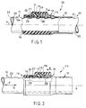
- Fig. 1 eine teilweise geschnittene Längsansicht der ersten Ausführungsform eines teleskopierbaren StaubsaugerSaugrohrs in der Verriegelungsstellung,
- Fig. 2 das Staubsauger-Saugrohr gemäß Fig. 1 in der entriegelten Stellung,
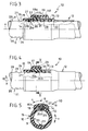
- Fig. 3 und 4 zwei weitere Ausführungsformen teleskopierbarer Staubsauger-Saugrohre in der Darstellungsweise gemäß den Fig. 1 und 2 und
- Fig. 5 einen Querschnitt entsprechend der mit V-V bezeichneten Schnittlinie in Fig. 4.
- 1 is a partially sectioned longitudinal view of the first embodiment of a telescopic vacuum cleaner suction pipe in the locked position,
- 2 the vacuum cleaner suction pipe according to FIG. 1 in the unlocked position,
- 3 and 4, two further embodiments of telescopic vacuum cleaner suction pipes in the representation according to FIGS. 1 and 2 and
- 5 shows a cross section corresponding to the section line labeled VV in FIG. 4.
In den Zeichnungen ist ein teleskopierbares Staubsauger-Saugrohr insgesamt mit der Bezugsziffer 10 bezeichnet. Das Saugrohr weist ein Innenrohr 11 und ein Außenrohr 12 auf. Das Außenrohr 12 bildet eine muffenartige Aufweitung 13. Innerhalb des zwischen Innenrohr-Außenmantelfläche 34 und Außenrohrinnenmantelfläche 33 befindlichen insgesamt mit 14 bezeichneten Freiraums ist ein im Querschnitt im wesentlichen kreisringförmiger Führungskörper 15 aus Kunststoff angeordnet. Im Führungskörper 15 aufgenommen ist jeweils ein entlang der Rohrlängsachse x translatorisch beweglicher Schieber 16 (Fig. 1 und 2,) 16a, (Fig. 3) sowie ein rotatorisch um die Rohrlängsachse x entlang der Umfangsrichtung u beweglicher Schieber 16b (Fig. 4 und 5).In the drawings, a telescopic vacuum cleaner suction tube is generally designated by the
Jeder Schieber 16, 16a, 16b durchgreift die Außenrohrwandung 13 mit einem Betätigungsansatz 17 innerhalb einer Aussparung 18. Jeder Betätigungsansatz 17 wiederum trägt eine Handhabe 19.Each
Jedes Innenrohr 11 weist eine Rastleiste 20 mit Rastausnehmungen 21 auf.Each
Bei den dargestellten Ausführungsformen be stehen das Innenrohr 11 und Außenrohr 12 aus Stahlblech. Die Rastleiste 20 mit den Rastausnehmungen 21 ist als relativ schmaler leistenartiger Streifen in die Innenrohrwandung 22 eingeprägt. Die Einprägung ist hierbei derart, daß jede Rastausnehmung 21 von der jeweils benachbarten Rastausnehmung 21 über einen unverformten kreiszylindrischen Rohrwandbereich 23 distanziert ist.In the illustrated embodiments, the
Jede Rastausnehmung 21 weist an einer axialen Endseite eine sich spitzwinklig geneigt zur Rohrlängsachse x erstrekkende Gleitflanke 24 für einen walzenartigen Rastkörper 25 (Fig. 1 und 2), für einen stegartigen Rastkörper 25a (Fig. 3) bzw. für einen Kugel-Rastkörper 25b (Fig. 4 und 5) auf.Each
An der anderen axialen Endseite einer jeden Rastausnehmung 21 ist mit einem relativ kleinen Krümmungsradius eine Sperr- bzw. Hemmflanke 26 ausgebildet. Und zwar weist eine jede Rastausnehmung 21 an ihrer zum Saugvorsatz (der Saugvorsatz ist nicht dargestellt, aber mit S und einem Pfeil angedeutet) wie zum Beispiel Saugbürste oder Saugdüse, weisenden axialen Endseite die gekrümmte Sperr- bzw. Hemmflanke 26 auf.On the other axial end side of each locking recess 21, a locking or inhibiting
Die jeweiligen Längsachsen der für längliche Rastkörper 25, 25a bestimmten Rastausnehmungen 21 (Fig. 1-3) erstrecken sich sekantial zum Körper des Innenrohrs 11, dessen Querschnitt kreiszylindrisch ist.The respective longitudinal axes of the latching recesses 21 (FIGS. 1-3) intended for
Die Rastausnehmungen 21 entsprechend den Fig. 4 und 5 sind, jedenfalls im Querschnitt gemäß Fig. 5, im wesentlichen kugelkalottenförmig ausgebildet, während der zugehörige Rastkörper 25b selbst - wie bereits vorerwähnt - Kugelgestalt aufweist.The
Allen dargestellten Ausführungsformen entsprechend den Fig. 1-5 ist als wesentliches Merkmal gemeinsam, daß Schieber (bzw. Niederhalter) 16, 16a, 16b und zugehörige Rastkörper 25, 25a, 25b gesonderte Bauteile bilden. Während des Sperrzustandes (Fig. 1 sowie Fig. 3-5) hält der jeweilige Schieber 16, 16a, 16b den jeweiligen Rastkörper 25, 25a, 25b zwangsweise innerhalb einer ausgewählten Rastausnehmung 21, so daß Innenrohr 11 und Außenrohr 12 unverschieblich zueinander gehalten sind.All of the illustrated embodiments corresponding to FIGS. 1-5 have in common as an essential feature that slide (or hold-down device) 16, 16a, 16b and associated
Falls jedoch der Schieber 16, 16a, 16b in Richtung o verschoben wird, öffnet der Schieber 16, 16a, 16b die Verbindung zum Freiraum 14, so daß der Rastkörper 25, 25a, 25b in der Lage ist, aus der Rastausnehmung 21 herauszugleiten (d.h., die beiden Teleskoprohre 11, 12 zu entkupplen), sobald eine Relativbewegung der beiden Teleskoprohre 11, 12 zueinander eingeleitet wird. In jedem Falle weist der Rastkörper 25, 25a, 25b eine relativ geringe Masse auf, so daß eine leichtgängiger Rastvorgang, also auch eine leichtgängige Verschieblichkeit der beiden Rohre 11, 12 zueinander, gewährleistet ist.However, if the
Die Funktion der einzelnen Ausführungsformen ist folgende:
Wie aus Fig. 1 ersichtlich, befindet sich der walzenförmige Rastkörper 25 in einer Rastausnehmung 21 und wird dort mittels einer Sperrnase 27 des Schiebers 16 niedergehalten.The function of the individual embodiments is as follows:
As can be seen from FIG. 1, the roller-
Sobald der Schieber 16 entgegen der Rückstellkraft einer lediglich gestrichelt eingezeichneten Schraubendruckfeder 28 betätigt wird, ergibt sich der Betriebszustand gemäß Fig. 2: Die Sperrnase 27 ist zurückgezogen, das Innenrohr 11 kann in Zugrichtung z nach links vom Außenrohr 12 weggezogen werden, wobei der walzenförmige Rastkörper 25 über jede Gleitflanke 24 völlig ungehindert hinweggleiten kann. Auch ein Ineinanderschieben der Rohrverbindung 10 in Druckrichtung d ist im dargestellten Zustand gemäß Fig. 2 möglich, da die Sperr- bzw. Hemmflanken 26 so ausgebildet sind, daß sie gerade noch ein Herausgleiten des jeweiligen Rastkörpers 25, 25a, 25b während der Verstellbewegung gestatten. Die Sperr- bzw. Hemmflanken 26 dienen einerseits einer während der Verstellbewegung fühl- bzw. hörbaren Rastmarkierung und bieten andererseits eine zusätzliche Sicherung der Sperrstellung (Fig. 1, Fig. 3 bis 5) auch für den Fall, daß die Druckkraft in Richtung d (starkes Anstoßen des Saugvorsatzes S gegen ein Hindernis während der Saugarbeit) relativ groß sein sollte. Auch ist es beim Ausführungsbeispiel gemäß Fig. 1 so, daß bei Auftreten einer relativ großen Kraft in Richtung d eine anfängliche Abrollbewegung des Walzenkörpers 25 eine Bewegung der Sperrnase 27 in Richtung z bzw. g, also eine zusätzliche Sicherung der Sperrstellung, bewirkt. Insoweit hat hier der Walzenkörper 25 etwa die Funktion eines sich zwischen zwei Zahnstangen abwälzenden Ritzels.As soon as the
Sobald sich der walzenförmige Rastkörper 25 gemäß Fig. 2 wieder im Tiefsten einer bestimmten Rastausnehmung 21 befindet, bewegt sich der Schieber 16 nach Bestätigungsentlastung unter der Wirkung der Schraubendruckfeder 28 in Schließrichtung g. Es ist noch wichtig zu erwähnen, daß eine Mitnahme bzw. Positionierung eines jeden Rastkörpers 25, 25a, 25b etwa nach Art eines Kugelkäfigs mittels einer schieberseitigen Öffnung 29 erfolgt.As soon as the roller-
Beim Ausführungsbeispiel gemäß Fig. 3 ist die Funktion ähnlich wie beim Ausführungsbeispiel gemäß den Fig. 1 und 2. Beim Ausführungsbeispiel gemäß Fig. 3 ist der stegartige Rastkörper 25a Bestandteil eines insgesamt mit 30 bezeichneten Rechtecksbügels bzw. -rahmens aus Draht. Der dem Verriegelungssteg 25a abgewandte Quersteg 31 des Bügels 30 ist innerhalb eines schieberseitigen Langloches 32 aufgenommen. Es ist vorstellbar, daß das Langloch 32 eine Verschiebung des Schiebers 16a in Richtung o gestattet, so daß die Sperrnase 27 den Zugang des Rastkörpers 25a zum Freiraum 14 herstellen kann, um den Verriegelungszustand, wie er in Fig. 3 dargestellt ist, aufzulösen.In the exemplary embodiment according to FIG. 3, the function is similar to that in the exemplary embodiment according to FIGS. 1 and 2. In the exemplary embodiment according to FIG. 3, the web-
Die Funktion der Ausführungsform gemäß den Fig. 4 und 5 ist grundsätzlich vergleichbar mit den Ausführungsformen gemäß den Fig. 1 bis 3, mit dem Unterschied, daß die Betätigung des Schiebers 16b nicht translatorisch in Richtung der Rohrlängsache x, sondern vielmehr rotatorisch um die Rohrlängsachse x herum entsprechend den in Fig. 5 eingetragenen Pfeilen o in Öffnungsrichtung und g in Schließrichtung erfolgt. Auch bei diesem Ausführungsbeispiel (Fig. 5) ist eine Sperrnase 27 zu erkennen.The function of the embodiment according to FIGS. 4 and 5 is fundamentally comparable to the embodiments according to FIGS. 1 to 3, with the difference that the actuation of the slide 16b is not translatory in the direction of the longitudinal pipe thing x, but rather rotatory about the longitudinal pipe axis x around in accordance with the arrows in Fig. 5 o in the opening direction and g in the closing direction. Also in this embodiment (Fig. 5) a
Im übrigen ist doch denkbar, daß die Anordnung 16, 16a, 16b, 25, 25a, 25b durch eine an sich bekannte Kugelrast ersetzbar wäre. Hierbei könnte die Handhabe 19 beibehalten werden oder sogar entfallen. Im letzteren Falle, müßte die Stärke der Rastkraft durch die Rückstellkraft einer nicht eingezeichneten Kugelrast-Feder, welche in diesem Falle den Niederhalter darstellen würde, variiert werden. Eine ähnliche Ausführungsform wäre auch im Zusammenhang mit Fig. 3 denkbar. Dort könnte der Bügel 30 mit seinen beiden Längsschenkeln innerhalb des Freiraums 14 zwischen Außenrohr-Innenmantelfläche 33 und Innenrohr-Außenmantelfläche 34 innerhalb des Führungskörpers 15 translatorisch geführt und entgegen der Rückstellkraft einer oder zweier nicht dargestellter Federn (Niederhalter) aus den Rastausnehmungen 21 ausrastbar sein. Bei dieser nicht dargestellten Ausführungsform würden der Rastkörper 25a und die korrelierenden Rastausnehmungen 21 nicht - wie in Fig. 3 eingetragen - oben sondern vielmehr diametral gegenüberliegend an der unteren Seite des Innenrohres 11 angeordnet sein. Die sickenartige Axialnut 35 wäre sodann - nicht wie in Fig. 3 dargestellt - unten, sondern vielmehr diametral gegenüberliegend oben vorgesehen.Otherwise, it is conceivable that the
Eine Verdrehsicherung zwischen Innenrohr 11 und Außenrohr 12 kommt wie folgt zustande: Der am Außenrohr 12 innerhalb der Aufweitung 13 in nicht näher dargestellter Weise (beispielsweise durch Klebung) drehgesicherte Führungskörper 15 greift (vgl. Fig. 5) mit einer Axialfeder 36 in die innenrohrseitig vorgesehene axiale Längssicke 35 ein. Zugleich wird hier ein Fehlluft erzeugender Luftabschluß erreicht. Die Anordnung ist hierbei im übrigen so getroffen, daß der vordere äußere Bereich des Führungskörpers 15 einen unverformten Rohrbereich 23 übergreift, wenn sich die Rastkörper 25, 25a, 25b in einer Rastausnehmung 21 befinden.An anti-rotation device between the
Die Erfindung sieht alternativ auch vor, Axialnut 35 und Rastausnehmungen 21 zu überlagern. So könnten die kugelförmigen Rastausnehmungen 21 gemäß Fig. 4 und 5 im Tiefsten einer um 180° umfangsversetzten Axialnut 35 (auch die Feder 36 wäre dann versetzt) eingeprägt sein.Alternatively, the invention also provides for
Claims (12)
- A telescopic vacuum cleaner suction tube (10) comprising an outer tube (12) with an axially extending locking strip (20), whose locking recesses (21) are imprinted in the wall (22) of the inner tube (11), a locking element (25; 25a; 25b), which cooperates with the locking recesses (21), locks the outer tube (12) and inner tube (11) relative to one another in an axially releasable manner, is held on the outer tube (12) so as to be radially movable for instance, is lockable by means of a holding-down device (16; 16a, 16b) and forms a separate component which is displaceable relative to the respective locking recess (21) into a locking or releasing position by means of the holding-down element (16; 16a; 16b) which acts as a control element and is displaceable independently of the locking element (25; 25a; 25b), the holding-down element (16; 16a; 16b) overlying the locking element (25; 25a; 25b) in its locking position and in its releasing position opening a free space (14) towards the locking recess (21), a form-locking safety device, which prevents a relative rotation of the inner and outer tubes (11, 12), comprising an axial groove (35) formed in the tube wall (22) of the inner tube (11), in which groove an axial guide rib (36) engages in a sealing-tight manner, which rib is associated with a circular cylindrical plastics material ring element (15), which is arranged between the inner tube (11) and a sleeve-shaped enlarged section (13) of the outer tube (12) and comprises an opening (29) for guiding the locking element (25; 25a; 25b), characterised in that for receiving the locking element (25; 25a; 25b) cooperating with the locking recesses (21) of the locking strip (20), the free space (14) is formed between the inner tube outer cylindrical surface (34) and the outer tube inner cylindrical surface (35) of the sleeve-shaped enlarged section (13), in which free space the holding-down element movable in the longitudinal (x) or circumferential (u) directions of the tube is also arranged, the holding-down element being guided by the plastics material ring element designed as a guide element (15) and engaging through the outer tube wall with an operating attachment (17) in a recess (18).
- A vacuum cleaner suction tube according to claim 1, characterised in that, at at least one axial end face, the respective locking recess (21) forms a sliding flank (24) for the locking element (25; 25a; 25b) extending inclined at an acute angle to the longitudinal axis (x) of the tube.
- A vacuum cleaner suction tube according to claim 1, characterised in that, at both of its axial end faces, the respective locking recess (21) forms a sliding flank (24) for the locking element (25; 25a; 25b) extending inclined at an acute angle to the longitudinal axis (x) of the tube.
- A vacuum cleaner suction tube according to claim 1 or 2, characterised in that, at one axial end face, the locking recess (21) forms a sliding flank (24) extending inclined at an acute angle to the longitudinal axis (x) of the tube and at the other axial end face forms a locking or checking flank (26) curved with a relatively small radius.
- A vacuum cleaner suction tube according to claim 4, characterised in that, at its axial end face pointing towards the suction accessory (at S), such as a suction brush or suction nozzle, the locking recess (21) comprises the curved locking or checking flank (26).
- A vacuum cleaner suction tube according to one of claims 1 to 5, characterised in that the longitudinal axes of the locking surface-flanks (24; 26) extend in the form of a secant relative to the circular cylindrical inner tube element (11).
- A vacuum cleaner suction tube according to one of the claims 1 to 6, characterised in that the locking element is a cylindrical (25; 25a) or spherical (25b) element.
- A vacuum cleaner suction tube according to claim 7, characterised in that the locking element is a roller-shaped element (25).
- A vacuum cleaner suction tube according to one of claims 1 to 6, characterised in that the locking element forms a cross web (25a) extending in the shape of a secant relative to the circular cylindrical inner element (11) of C-shaped or rectangular wire bracket (30), which is displaceably guided or articulated so as to pivot at least indirectly (at 32) on the outer tube (12) with its side (at 31) facing away from the cross web (25a).
- A vacuum cleaner suction tube according to claim 8 or 9, characterised in that the displaceably guided bracket (30) comprising the cross web (25a) as a locking element is pulled or pushed by means of at least one spring as a holding-down element against the inner tube-side locking strip (20).
- A vacuum cleaner suction tube according to one of the preceding claims, characterised in that the guide element (15) secured against rotation on the outer tube (12) engages fully with an axial guide or sealing rib (36) in the inner tube-side axial longitudinal corrugation (35).
- A vacuum cleaner suction tube according to one of the preceding claims, characterised in that the locking recesses (21) penetrate the axial corrugation (35) transversely or are imprinted as spherical segment-shaped locking recesses at the deepest point of the axial corrugation (35).
Priority Applications (1)
| Application Number | Priority Date | Filing Date | Title |
|---|---|---|---|
| AT87119407T ATE72743T1 (en) | 1987-06-03 | 1987-12-31 | TELESCOPIC VACUUM CLEANER SUCTION TUBE. |
Applications Claiming Priority (2)
| Application Number | Priority Date | Filing Date | Title |
|---|---|---|---|
| DE3718578 | 1987-06-03 | ||
| DE3718578A DE3718578C1 (en) | 1987-06-03 | 1987-06-03 | Telescopic suction tube for vacuum cleaner - has inner section forming arresting strip with deformed region with arresting recesses |
Publications (2)
| Publication Number | Publication Date |
|---|---|
| EP0293518A1 EP0293518A1 (en) | 1988-12-07 |
| EP0293518B1 true EP0293518B1 (en) | 1992-02-26 |
Family
ID=6328954
Family Applications (1)
| Application Number | Title | Priority Date | Filing Date |
|---|---|---|---|
| EP87119407A Expired - Lifetime EP0293518B1 (en) | 1987-06-03 | 1987-12-31 | Telescopic vacuum cleaner suction hose |
Country Status (5)
| Country | Link |
|---|---|
| EP (1) | EP0293518B1 (en) |
| AT (1) | ATE72743T1 (en) |
| DE (1) | DE3776902D1 (en) |
| ES (1) | ES2030706T3 (en) |
| GR (1) | GR3004236T3 (en) |
Cited By (1)
| Publication number | Priority date | Publication date | Assignee | Title |
|---|---|---|---|---|
| US11137006B2 (en) | 2016-08-17 | 2021-10-05 | D & M Designs Llc | Collapsible telescoping pole |
Families Citing this family (15)
| Publication number | Priority date | Publication date | Assignee | Title |
|---|---|---|---|---|
| ES2107614T3 (en) * | 1991-06-28 | 1997-12-01 | Omec Spa | TELESCOPIC EXTENSION FOR A VACUUM CLEANER. |
| DE19615814C2 (en) * | 1995-04-27 | 1998-01-29 | Zelmer | Telescopic vacuum cleaner pipe |
| DE19524290C1 (en) * | 1995-07-06 | 1996-08-14 | Froh Roehren | Telescopic suction tube for vacuum cleaner with outer and inner tube |
| PL181955B1 (en) * | 1996-10-28 | 2001-10-31 | Zelmer | Telescoped suction tube for vacuum cleaners |
| AUPP124098A0 (en) * | 1998-01-07 | 1998-01-29 | Tubalco Manufacturing Pty Ltd | Locking arrangement for telescopically moving tubes |
| JP2003534024A (en) * | 1998-06-30 | 2003-11-18 | 株式会社大宇エレクトロニクス | Vacuum cleaner foldable suction pipe assembly |
| EP1092383B1 (en) | 1999-10-11 | 2008-05-07 | OMEC S.p.A. | Telescopic extension for an electric household appliance |
| CN2401136Y (en) | 2000-01-12 | 2000-10-18 | 徐为尔 | Extension tube for suction cleaner |
| KR200200566Y1 (en) * | 2000-03-07 | 2000-10-16 | 은성전자주식회사 | Inhalation pipe of vacuum cleaner |
| CN2449639Y (en) | 2000-09-30 | 2001-09-26 | 徐为尔 | Telescopic suction tube for suction cleaner |
| GB0425626D0 (en) * | 2004-11-22 | 2004-12-22 | Hoover Ltd | Wand assemblies for vacuum cleaners |
| CN1799487A (en) * | 2005-09-16 | 2006-07-12 | 邬永龙 | Telescopic dust collection pipe of dust cleaner |
| CN100367902C (en) * | 2005-10-24 | 2008-02-13 | 徐为尔 | Telescopic sucking tube of vacuum cleaner |
| DE102006006189B3 (en) * | 2006-02-09 | 2007-06-06 | Wolfgang Hermes | Fodder and water device for domestic animals e.g. for dogs, has operating handle guided at adjuster, which acts upon a form-fit or clamping body, which are locked on stand-pole or detached from stand-pole |
| DE102013101911B4 (en) * | 2013-02-26 | 2014-11-06 | Fischer Rohrtechnik Gmbh | Vacuum cleaner suction tube |
Citations (2)
| Publication number | Priority date | Publication date | Assignee | Title |
|---|---|---|---|---|
| US3351363A (en) * | 1964-12-23 | 1967-11-07 | Electrolux Corp | Adjustable length wand |
| US3351359A (en) * | 1964-12-23 | 1967-11-07 | Electrolux Corp | Adjustable length wand |
Family Cites Families (6)
| Publication number | Priority date | Publication date | Assignee | Title |
|---|---|---|---|---|
| FR1263595A (en) * | 1959-07-20 | 1961-06-09 | Electrische App N En Metaalfab | Coupling fitting |
| US3244437A (en) * | 1964-01-28 | 1966-04-05 | Electrolux Corp | Adjustable length vacuum cleaner wand |
| DE2618065C3 (en) * | 1976-04-24 | 1979-08-02 | Carl Froh Roehrenwerk Gmbh & Co, 5768 Sundern | Sleeveless telescopic pipe connection |
| DE3102898A1 (en) * | 1981-01-29 | 1982-08-26 | Licentia Patent-Verwaltungs-Gmbh, 6000 Frankfurt | Clamping device on two telescopic suction pipes |
| US4494270A (en) * | 1983-03-25 | 1985-01-22 | Electrolux Corporation | Vacuum cleaner wand |
| US4577837A (en) * | 1984-07-30 | 1986-03-25 | Marvin Berg | Locking mechanism for extendible telescoping tubular members |
-
1987
- 1987-12-31 ES ES198787119407T patent/ES2030706T3/en not_active Expired - Lifetime
- 1987-12-31 DE DE8787119407T patent/DE3776902D1/en not_active Expired - Lifetime
- 1987-12-31 EP EP87119407A patent/EP0293518B1/en not_active Expired - Lifetime
- 1987-12-31 AT AT87119407T patent/ATE72743T1/en not_active IP Right Cessation
-
1992
- 1992-04-01 GR GR920400608T patent/GR3004236T3/el unknown
Patent Citations (2)
| Publication number | Priority date | Publication date | Assignee | Title |
|---|---|---|---|---|
| US3351363A (en) * | 1964-12-23 | 1967-11-07 | Electrolux Corp | Adjustable length wand |
| US3351359A (en) * | 1964-12-23 | 1967-11-07 | Electrolux Corp | Adjustable length wand |
Cited By (1)
| Publication number | Priority date | Publication date | Assignee | Title |
|---|---|---|---|---|
| US11137006B2 (en) | 2016-08-17 | 2021-10-05 | D & M Designs Llc | Collapsible telescoping pole |
Also Published As
| Publication number | Publication date |
|---|---|
| ES2030706T3 (en) | 1992-11-16 |
| GR3004236T3 (en) | 1993-03-31 |
| DE3776902D1 (en) | 1992-04-02 |
| EP0293518A1 (en) | 1988-12-07 |
| ATE72743T1 (en) | 1992-03-15 |
Similar Documents
| Publication | Publication Date | Title |
|---|---|---|
| EP0293518B1 (en) | Telescopic vacuum cleaner suction hose | |
| DE69200140T2 (en) | Telescopic pipe connection of a vacuum cleaner. | |
| EP0858762B1 (en) | Telescopic vacuum cleaner suction hose | |
| DE2711124C2 (en) | Hand pipette | |
| EP1208787B1 (en) | Telescopic vacuum cleaner suction pipe | |
| DE2924707C2 (en) | ||
| EP0552481B1 (en) | Telescopic vacuum cleaner suction hose | |
| DE19924450C1 (en) | Telescopic vacuum cleaner suction tube has actuator for the locking body in form of rotation body acting directly on locking body with spring for securing actuator locking position | |
| DE69911362T2 (en) | Arrangement for connecting two tubular elements | |
| EP0859185B1 (en) | Arrangement for the connection of two tubular elements | |
| DE3718578C1 (en) | Telescopic suction tube for vacuum cleaner - has inner section forming arresting strip with deformed region with arresting recesses | |
| DE3046286A1 (en) | LATCHING FOR TELESCOPICOUS GUIDES | |
| DE68903707T2 (en) | ROLLING CURTAIN WITH A BRAKE DEVICE WITH A CYLINDRICAL CAM. | |
| EP0859106B1 (en) | Upper and lower closure device for doors with an automatic lock | |
| DE3917351C2 (en) | ||
| DE4422171A1 (en) | Emergency switch-off button for working machines | |
| DE2253732C3 (en) | Device for adjusting the output member of a motion gear | |
| DE8717941U1 (en) | Telescopic vacuum cleaner suction tube | |
| DE3701433A1 (en) | TAP PLANT WITH TAP HEAD | |
| DE1760544C3 (en) | Door lock for a loading door of a washing machine or dishwasher with an all-round seal | |
| DE10034471B4 (en) | Ram boring machine | |
| DE2556616C3 (en) | Fastener feed device on a pneumatic tool | |
| DE2930840C2 (en) | End seal of an annular space that accommodates a cable | |
| EP0079617A2 (en) | Pressure relief valve for a sphygmomanometer | |
| DE2134732C3 (en) | Quick coupling |
Legal Events
| Date | Code | Title | Description |
|---|---|---|---|
| PUAI | Public reference made under article 153(3) epc to a published international application that has entered the european phase |
Free format text: ORIGINAL CODE: 0009012 |
|
| 17P | Request for examination filed |
Effective date: 19881010 |
|
| AK | Designated contracting states |
Kind code of ref document: A1 Designated state(s): AT BE CH DE ES FR GB GR IT LI LU NL SE |
|
| 17Q | First examination report despatched |
Effective date: 19900222 |
|
| ITF | It: translation for a ep patent filed | ||
| GRAA | (expected) grant |
Free format text: ORIGINAL CODE: 0009210 |
|
| AK | Designated contracting states |
Kind code of ref document: B1 Designated state(s): AT BE CH DE ES FR GB GR IT LI LU NL SE |
|
| REF | Corresponds to: |
Ref document number: 72743 Country of ref document: AT Date of ref document: 19920315 Kind code of ref document: T |
|
| GBT | Gb: translation of ep patent filed (gb section 77(6)(a)/1977) | ||
| REF | Corresponds to: |
Ref document number: 3776902 Country of ref document: DE Date of ref document: 19920402 |
|
| ET | Fr: translation filed | ||
| REG | Reference to a national code |
Ref country code: ES Ref legal event code: FG2A Ref document number: 2030706 Country of ref document: ES Kind code of ref document: T3 |
|
| PLBI | Opposition filed |
Free format text: ORIGINAL CODE: 0009260 |
|
| REG | Reference to a national code |
Ref country code: GR Ref legal event code: FG4A Free format text: 3004236 |
|
| 26 | Opposition filed |
Opponent name: OMEC S.P.A. Effective date: 19921120 |
|
| NLR1 | Nl: opposition has been filed with the epo |
Opponent name: OMEC S.P.A. |
|
| PLAB | Opposition data, opponent's data or that of the opponent's representative modified |
Free format text: ORIGINAL CODE: 0009299OPPO |
|
| R26 | Opposition filed (corrected) |
Opponent name: OMEC S.P.A. Effective date: 19921120 |
|
| EPTA | Lu: last paid annual fee | ||
| EAL | Se: european patent in force in sweden |
Ref document number: 87119407.2 |
|
| PLBN | Opposition rejected |
Free format text: ORIGINAL CODE: 0009273 |
|
| STAA | Information on the status of an ep patent application or granted ep patent |
Free format text: STATUS: OPPOSITION REJECTED |
|
| 27O | Opposition rejected |
Effective date: 19950227 |
|
| NLR2 | Nl: decision of opposition | ||
| REG | Reference to a national code |
Ref country code: CH Ref legal event code: PFA Free format text: CARL FROH ROEHRENWERK GMBH & CO. TRANSFER- CARL FROH GMBH |
|
| REG | Reference to a national code |
Ref country code: FR Ref legal event code: CD Ref country code: FR Ref legal event code: CJ |
|
| BECN | Be: change of holder's name |
Effective date: 19991027 |
|
| NLT1 | Nl: modifications of names registered in virtue of documents presented to the patent office pursuant to art. 16 a, paragraph 1 |
Owner name: CARL FROH GMBH;CARL FROH GMBH & CO |
|
| REG | Reference to a national code |
Ref country code: ES Ref legal event code: PC2A |
|
| REG | Reference to a national code |
Ref country code: CH Ref legal event code: NV Representative=s name: MOINAS & SAVOYE SA |
|
| REG | Reference to a national code |
Ref country code: CH Ref legal event code: PUE Owner name: CARL FROH GMBH TRANSFER- FROH HOUSE TECH GMBH & CO |
|
| NLT1 | Nl: modifications of names registered in virtue of documents presented to the patent office pursuant to art. 16 a, paragraph 1 |
Owner name: FROH HOUSE TECH GMBH & CO. KG |
|
| REG | Reference to a national code |
Ref country code: ES Ref legal event code: PC2A |
|
| REG | Reference to a national code |
Ref country code: FR Ref legal event code: CA |
|
| REG | Reference to a national code |
Ref country code: GB Ref legal event code: IF02 |
|
| PGFP | Annual fee paid to national office [announced via postgrant information from national office to epo] |
Ref country code: GR Payment date: 20041228 Year of fee payment: 18 |
|
| APAH | Appeal reference modified |
Free format text: ORIGINAL CODE: EPIDOSCREFNO |
|
| REG | Reference to a national code |
Ref country code: GB Ref legal event code: 732E |
|
| REG | Reference to a national code |
Ref country code: CH Ref legal event code: PFA Owner name: CARL FROH GMBH Free format text: FROH HOUSE TECH GMBH & CO. KG#AM LINDHOEVEL 1#59846 SUNDERN (DE) -TRANSFER TO- CARL FROH GMBH#157, HACHENER STRASSE#59846 SUNDERN (DE) |
|
| NLS | Nl: assignments of ep-patents |
Owner name: CARL FROH GMBH Effective date: 20060421 |
|
| REG | Reference to a national code |
Ref country code: ES Ref legal event code: PC2A |
|
| REG | Reference to a national code |
Ref country code: FR Ref legal event code: TP |
|
| PGFP | Annual fee paid to national office [announced via postgrant information from national office to epo] |
Ref country code: GB Payment date: 20061218 Year of fee payment: 20 |
|
| PGFP | Annual fee paid to national office [announced via postgrant information from national office to epo] |
Ref country code: AT Payment date: 20061222 Year of fee payment: 20 |
|
| PGFP | Annual fee paid to national office [announced via postgrant information from national office to epo] |
Ref country code: ES Payment date: 20061226 Year of fee payment: 20 |
|
| PGFP | Annual fee paid to national office [announced via postgrant information from national office to epo] |
Ref country code: NL Payment date: 20061229 Year of fee payment: 20 Ref country code: SE Payment date: 20061229 Year of fee payment: 20 |
|
| PGFP | Annual fee paid to national office [announced via postgrant information from national office to epo] |
Ref country code: IT Payment date: 20061231 Year of fee payment: 20 |
|
| PGFP | Annual fee paid to national office [announced via postgrant information from national office to epo] |
Ref country code: BE Payment date: 20070103 Year of fee payment: 20 |
|
| PGFP | Annual fee paid to national office [announced via postgrant information from national office to epo] |
Ref country code: LU Payment date: 20070110 Year of fee payment: 20 |
|
| PGFP | Annual fee paid to national office [announced via postgrant information from national office to epo] |
Ref country code: CH Payment date: 20070111 Year of fee payment: 20 |
|
| PGFP | Annual fee paid to national office [announced via postgrant information from national office to epo] |
Ref country code: DE Payment date: 20070123 Year of fee payment: 20 |
|
| BE20 | Be: patent expired |
Owner name: CARL *FROH G.M.B.H. Effective date: 20071231 |
|
| REG | Reference to a national code |
Ref country code: GB Ref legal event code: PE20 |
|
| PG25 | Lapsed in a contracting state [announced via postgrant information from national office to epo] |
Ref country code: NL Free format text: LAPSE BECAUSE OF EXPIRATION OF PROTECTION Effective date: 20071231 |
|
| REG | Reference to a national code |
Ref country code: CH Ref legal event code: PL |
|
| NLV7 | Nl: ceased due to reaching the maximum lifetime of a patent |
Effective date: 20071231 |
|
| REG | Reference to a national code |
Ref country code: ES Ref legal event code: FD2A Effective date: 20080102 |
|
| EUG | Se: european patent has lapsed | ||
| PG25 | Lapsed in a contracting state [announced via postgrant information from national office to epo] |
Ref country code: GB Free format text: LAPSE BECAUSE OF EXPIRATION OF PROTECTION Effective date: 20071230 Ref country code: GR Free format text: LAPSE BECAUSE OF NON-PAYMENT OF DUE FEES Effective date: 19920226 Ref country code: ES Free format text: LAPSE BECAUSE OF EXPIRATION OF PROTECTION Effective date: 20080102 |
|
| PGFP | Annual fee paid to national office [announced via postgrant information from national office to epo] |
Ref country code: FR Payment date: 20061227 Year of fee payment: 20 |