EP0287351A2 - Imprimante - Google Patents
Imprimante Download PDFInfo
- Publication number
- EP0287351A2 EP0287351A2 EP88303326A EP88303326A EP0287351A2 EP 0287351 A2 EP0287351 A2 EP 0287351A2 EP 88303326 A EP88303326 A EP 88303326A EP 88303326 A EP88303326 A EP 88303326A EP 0287351 A2 EP0287351 A2 EP 0287351A2
- Authority
- EP
- European Patent Office
- Prior art keywords
- ribbon
- carriage
- printing
- take
- ink ribbon
- Prior art date
- Legal status (The legal status is an assumption and is not a legal conclusion. Google has not performed a legal analysis and makes no representation as to the accuracy of the status listed.)
- Granted
Links
Images


Classifications
-
- B—PERFORMING OPERATIONS; TRANSPORTING
- B41—PRINTING; LINING MACHINES; TYPEWRITERS; STAMPS
- B41J—TYPEWRITERS; SELECTIVE PRINTING MECHANISMS, i.e. MECHANISMS PRINTING OTHERWISE THAN FROM A FORME; CORRECTION OF TYPOGRAPHICAL ERRORS
- B41J35/00—Other apparatus or arrangements associated with, or incorporated in, ink-ribbon mechanisms
- B41J35/36—Alarms, indicators, or feed disabling devices responsive to ink ribbon breakage or exhaustion
-
- B—PERFORMING OPERATIONS; TRANSPORTING
- B41—PRINTING; LINING MACHINES; TYPEWRITERS; STAMPS
- B41J—TYPEWRITERS; SELECTIVE PRINTING MECHANISMS, i.e. MECHANISMS PRINTING OTHERWISE THAN FROM A FORME; CORRECTION OF TYPOGRAPHICAL ERRORS
- B41J33/00—Apparatus or arrangements for feeding ink ribbons or like character-size impression-transfer material
- B41J33/02—Ribbon arrangements
- B41J33/06—Ribbons associated, but not moving, with typewriter platens, e.g. extending transversely to the length of the platen
-
- B—PERFORMING OPERATIONS; TRANSPORTING
- B41—PRINTING; LINING MACHINES; TYPEWRITERS; STAMPS
- B41J—TYPEWRITERS; SELECTIVE PRINTING MECHANISMS, i.e. MECHANISMS PRINTING OTHERWISE THAN FROM A FORME; CORRECTION OF TYPOGRAPHICAL ERRORS
- B41J33/00—Apparatus or arrangements for feeding ink ribbons or like character-size impression-transfer material
- B41J33/14—Ribbon-feed devices or mechanisms
- B41J33/38—Slow, e.g. "creep", feed mechanisms
- B41J33/388—Slow, e.g. "creep", feed mechanisms the ribbon being fed only when type impression takes place
Definitions
- This invention relates to a printer, and more particularly to a printer such as an electro-thermic printer which has a ribbon cassette mounted in a stationary state independently of the carriage, and lets off the ink ribbon from the ribbon cassette and recovers it into the ribbon cassette by means of a print head mounted on the carriage along with the reciprocal motion of the carriage in the printing direction.
- a printer such as an electro-thermic printer which has a ribbon cassette mounted in a stationary state independently of the carriage, and lets off the ink ribbon from the ribbon cassette and recovers it into the ribbon cassette by means of a print head mounted on the carriage along with the reciprocal motion of the carriage in the printing direction.
- the conventional printer using an ink ribbon was generally composed so as to mount the ribbon cassette on the carriage together with the print head, but the weight of the entire carriage was increased by mounting the ribbon cassette and ribbon take-up mechanism, and it was hard to move the carriage at high speed. Besides, in order to move this heavy carriage at high speed, a driving motor of a high output torque was required, and in this respect, too, the size of the carriage was enlarged, and the ribbon cassette that could be mounted on the carriage was limited accordingly.
- This printer however, of the ribbon cassette fixed type involves the following technical problems that must be solved. That is, although the carriage can be reduced in size and weight and can be moved at high speed because ribbon cassette is not mounted on it, but when transferring the ink ribbon, whenever the carriage is returned to the initial printing position (home positioned), a friction member for fixing in order to press and fix the ink ribbon to the platen at the initial printing position is separated from the platen, and the take-up side reel is rotated in the take-up direction, and the unused ink ribbon for the portion of the length to record while the carriage makes one reciprocal stroke is preliminarily taken up on the take-up side reel.
- the friction member presses and fixes the ink ribbon to the platen by means of driving source such as magnet to define the let-off of the ink ribbon from the feed side reel, and the carriage moves in the printing direction, and along with this movement, the unused ink ribbon which has been previously taken up is let off from the take-up side reel, and is printed by the print head, and when returning as the carriage reaches the end of printing direction, the used ink ribbon is taken up by the take-up side reel, and the same operation is repeated.
- driving source such as magnet
- the ink ribbon in the length necessary for one reciprocal stroke of the carriage is preliminarily taken up on the take-up side reel and the initial printing portion of this ink ribbon is fixed by the friction member, if non-printing blank portions occur continuously in the printing process, the print head is released from the ink ribbon, but these portions remain unused, and are taken up on the take-up side reel when returning the carriage. That is, since the action generally known as ribbon skip cannot be effected, the ink ribbon is consumed purposelessly.
- this invention presents a printer in which a ribbon cassette having an ink ribbon wound between a feed reel and a take-up reel is mounted in a stationary state independently of a carriage, and the ink ribbon is let off from said ribbon cassette and is recovered into the ribbon cassette by means of a print head mounted on the carriage along with the movement of the carriage in the printing direction.
- Said carriage is provided with a control roller which is disposed on the transfer route of the ink ribbon and is controlled so as to transfer the ink ribbon in the length corresponding to the printing portion at every printing by said print head in the printing action in the direction of said take-up reel and to fix the ink ribbon when said carriage returns or when transferring without printing, and between said reels is disposed a reel control mechanism which applies a rotating force of small torque of such as extent as to slip with respect to the ribbon let-off force by said print head to said both reels in printing action in the take-up rotating direction, and applies a rotating force of large torque to said both reels when said carriage returns in the take-up rotating direction.
- thermo-melting ink of the ink ribbon melted in the form of a character pattern is transferred on the printing paper, and a character is printed, and at this time the ink ribbon in the length corresponding to this printing is transferred in the take-up reel direction by the control roller.
- the print head is released from the ink ribbon and the control roller fixes the ink ribbon while the carriage moves in the printing direction, so that the ink ribbon can be drawn out of the ribbon cassette. That is, ribbon skip action is effected, and the ink ribbon can be saved accordingly.
- the carriage reaches the terminal end in the printing direction, the print heat is released from the ink ribbon, and the carriage is returned to the initial printing position while the controller is fixing the ink ribbon, and the unused portion and printed portion of the ink ribbon are taken up, respectively on the feed reel and take-up reel which are provided with a rotating direction of large torque in the take-up rotating direction by the reel control mechanism.
- Fig. 1 to Fig. 7 refer to one of the embodiments of a printer of this invention, in which:
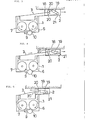
- Fig. 1 is a schematic plan view of a ribbon cassette 1 and a carriage 2 which are essential parts of this invention
- Fig. 2 is a schematic drawing showing the entire printing mechanism.
- a feed reel 4 and a take-up reel 5 of an ink ribbon 3 are disposed parallel, and gears 6, 7 are affixed to these reels 4, 5 as their control mechanism, and a prime gear 9 mounted on a motor shaft of a ribbon control motor 8 is meshed with the take-up side gear 7, and the rotation of this prime gear 9 is transmitted to the feed side gear 6 by way of a transmission gear 10.
- a rotating force is provided in the take-up rotating direction indicated by the arrow in the same drawing, on the both reels 4, 5 through the transmission gear 10, feed and take-up side gears 6, 7.
- This rotating force is, in printing action, a small torque so as to slip with respect to the draw-out force by a print head which is described below, and becomes a large torque when the carriage 2 returns.
- the reel torque is set so that the take-up side torque is larger than the feed side torque.
- This ribbon cassette is mounted in a stationary state being independent of the carriage, on a specified plate 100 of the printer, and is detachable together therewith.
- This ribbon cassette can be used on both face and back sides, being in a symmetrical configuration having a guide roller for smoothly leading out the ink ribbon outside and a guide part 12 disposed at right and left symmetrical positions, and the ribbon pancake is exchangeable.
- a ribbon end sensor 13 is provided at a specified position.
- a timing belt 17 wound on a prime side pulley 15 mounted on a printing motor 14 and a guide pulley 16 is applied, and the carriage 2 is moved reciprocally in the printing direction along a flat platen 18 by turning of this timing belt 17.
- This carriage 2 is provided with, for example, a print head 19 having a specified number of heating elements disposed in a matrix form and a pair of control rollers 20 and a guide roller 21.
- the print head 19 is disposed so as to be freely rotatable in the arrow direction by a head motor (not shown) located beneath the carriage from one end as the fulcrum, and a printing electrode part composed of said specified number of heating elements is provided at this free end.
- the pair of control rollers 20 are controlled in rotation so as to feed the ink ribbon 3 by the portion corresponding to the printing length in the direction to the take-up side reel 5 at every printing action of the print head 19 to the recording paper.
- Three feed rollers 23 rotated by a paper feed motor 22 are attached to the flat platen 18, and a paper end sensor 24 for detecting the end of recording paper sent by each feed roller 23 is provided near a roller shaft 25 of the feed roller 23, and moreover a cassette detection switch 26 to detect whether the ribbon cassette 1 is set in place or not, and a home position switch 27 to detect the return state of the carriage 2 to the initial printing position are disposed at specified positions.
- Fig. 6 the relation between the ribbon cassette 1 and carriage 2 is explained.
- the both control rollers 20 are spaced from each other at the carriage 2, and the print head 19 is also released from the platen 18, and when the ribbon cassette 1 is loaded, the ink ribbon 3 is inserted between the both control rollers 20.
- this ribbon cassette 1 is set in the specified position of the printer main body, it is detected by the cassette detection switch 26, and the print head 19 turns in the arrow direction as shown in fig.
- the head motor rotates the print head 19 in the direction to contact with the platen 18 as shown in Fig. 7(b), and immediately the print head 19 is rotated in the direction to be separated from the platen 18.
- the printing motor 14 is rotated reversely as shown in fig. 7(a), and the carriage 2 is moved toward the initial printing position, and, at time t3, when the carriage 2 returns to the initial printing position, the printing motor 15 slightly rotates in normal direction to set the carriage 2 in the specified initial printing position.
- the printing motor 15 slightly rotates in normal direction to set the carriage 2 in the specified initial printing position.
- the ribbon control motor 8 is rotated to move the ink ribbon 3 by a specified length. Then, at time t4, the head motor rotates to move the print head to the platen 18 side, and the print head 19 is pressed on the recording paper 28 through the ink ribbon 3, so as to be ready to print.
- the both control rollers 20 rotate in the arrow direction in Fig. 3 to transfer the ink ribbon 3 by the portion corresponding to the printing length in the direction to the take-up reel 5, and when not printing, that is, when the carriage 2 moves, the ink ribbon 3 is held and fixed to draw out the ink ribbon 3 from between the both reels 4, 5.
- the head motor rotates the print head 19 in the direction to be separated from the platen 18.
- the quantity of rotation at this time is, as obvious from Fig. 7(b), about half of the usual rotation, and the printing electrode part of the print head 19 is slightly spaced from the recording paper 28 as shown in Fig. 4.
- the ribbon control motor 8 stops rotating.
- the carriage 2 is moved in the printing direction as indicated by the arrow in Fig. 4 by the rotation of the printing motor 14, and, at this time, since the both control rollers 20 are holding and fixing the ink ribbon 3, the ink ribbon 3 is drawn out from the both reels 4, 5.
- the both control rollers 20 is pinching and fixing the ink ribbon 3, and the unused and used ink ribbons are taken up on the both reels 4, 5.
- the rotation of the printing motor 14 is stopped as shown in Fig. 7(a), and later at time t14 the rotation of the ribbon control motor 8 stops as shown in Fig. 79c).
- the head motor rotates as shown in Fig. 7(b) to move the print head 19 to the specified position, thereby opening a specified space against the recording paper 28, and at time t16 the paper feed motor 22 rotates as shown in Fig. 7(d), and the recording paper 28 is fed.
- the printer of this invention aside from the advantages of the ribbon cassette fixed type, such as high speed, small size, and use of large-sized ribbon cassette, since the ink ribbon can be transferred by the portion of the printing length by the print head at the time of printing by the newly installed control rollers, there is no loss in ribbon take-up, and faster operation is realized, and moreover the ribbon skip action which was difficult in the conventional ribbon cassette type can be easily effected, and the ink ribbon can be saved, so that great economical effects can be obtained.
Applications Claiming Priority (2)
| Application Number | Priority Date | Filing Date | Title |
|---|---|---|---|
| JP62090412A JPS63254087A (ja) | 1987-04-13 | 1987-04-13 | 印字装置 |
| JP90412/87 | 1987-04-13 |
Publications (3)
| Publication Number | Publication Date |
|---|---|
| EP0287351A2 true EP0287351A2 (fr) | 1988-10-19 |
| EP0287351A3 EP0287351A3 (en) | 1990-05-02 |
| EP0287351B1 EP0287351B1 (fr) | 1993-09-15 |
Family
ID=13997874
Family Applications (1)
| Application Number | Title | Priority Date | Filing Date |
|---|---|---|---|
| EP88303326A Expired - Lifetime EP0287351B1 (fr) | 1987-04-13 | 1988-04-13 | Imprimante |
Country Status (4)
| Country | Link |
|---|---|
| US (2) | US4952086A (fr) |
| EP (1) | EP0287351B1 (fr) |
| JP (1) | JPS63254087A (fr) |
| DE (1) | DE3884038T2 (fr) |
Cited By (1)
| Publication number | Priority date | Publication date | Assignee | Title |
|---|---|---|---|---|
| US5088846A (en) * | 1987-04-13 | 1992-02-18 | Sharp Kabushiki Kaisha | Printer of ribbon cassette fixed type |
Families Citing this family (8)
| Publication number | Priority date | Publication date | Assignee | Title |
|---|---|---|---|---|
| US5383733A (en) * | 1992-07-24 | 1995-01-24 | Summagraphics Corporation | Ribbon cassette for a printer |
| US5613785A (en) * | 1993-03-24 | 1997-03-25 | Seiko Precision Inc. | Dot impact printer having a ink ribbon loading means |
| US5794242A (en) * | 1995-02-07 | 1998-08-11 | Digital Equipment Corporation | Temporally and spatially organized database |
| CN1273307C (zh) * | 1999-01-07 | 2006-09-06 | 精工爱普生株式会社 | 具有色带卷取机构的打印机 |
| US7059791B2 (en) * | 2002-09-19 | 2006-06-13 | Dymo | Tape printer |
| US9116641B2 (en) | 2004-11-30 | 2015-08-25 | Panduit Corp. | Market-based labeling system and method |
| US9061522B2 (en) * | 2005-03-16 | 2015-06-23 | Panduit Corp. | Reversible printer assembly |
| EP2392465A3 (fr) * | 2010-06-03 | 2015-03-11 | JVM Co., Ltd. | Imprimante pour machine d'emballage automatique et procédé de contrôle associé |
Citations (3)
| Publication number | Priority date | Publication date | Assignee | Title |
|---|---|---|---|---|
| GB2089734A (en) * | 1980-12-11 | 1982-06-30 | Sony Corp | Printing apparatus |
| JPS58217384A (ja) * | 1982-06-11 | 1983-12-17 | Canon Inc | 記録装置 |
| US4621270A (en) * | 1984-07-30 | 1986-11-04 | Oki Electric Industry Co., Ltd. | Multi-color printer |
Family Cites Families (21)
| Publication number | Priority date | Publication date | Assignee | Title |
|---|---|---|---|---|
| IT1030105B (it) * | 1975-02-10 | 1979-03-30 | C Spa | Dispositivo per trasferire un nastro da una bobina di alimentazione ad una bobina di raccolta |
| US4264224A (en) * | 1979-03-19 | 1981-04-28 | International Business Machines Corporation | Off-the-carrier ribbon feed and drive on a high speed movable-carrier impact printer |
| CH647200A5 (de) * | 1979-09-26 | 1985-01-15 | Qume Corp | Schreibmaschine. |
| US4396305A (en) * | 1981-01-22 | 1983-08-02 | Scm Corporation | Ribbon Cartridge handling apparatus |
| JPS57201675A (en) * | 1981-06-08 | 1982-12-10 | Fuji Xerox Co Ltd | Transfer-type heat-sensitive recorder |
| JPS599083A (ja) * | 1982-07-09 | 1984-01-18 | Canon Inc | 記録装置 |
| JPS59133089A (ja) * | 1983-01-19 | 1984-07-31 | Silver Seiko Ltd | タイプライタ |
| JPS59185687A (ja) * | 1983-04-08 | 1984-10-22 | Canon Inc | 印字装置 |
| JPS59217548A (ja) * | 1983-05-23 | 1984-12-07 | Hitachi Ltd | 感熱転写記録装置 |
| JPS6046285A (ja) * | 1983-08-24 | 1985-03-13 | Alps Electric Co Ltd | 熱転写プリンタ |
| JPS60120086A (ja) * | 1983-11-30 | 1985-06-27 | Tokyo Electric Co Ltd | リボン位置切換装置 |
| JPS60120085A (ja) * | 1983-12-02 | 1985-06-27 | Tokyo Electric Co Ltd | サ−マルプリンタの印字リボン送り装置 |
| JPS60194557U (ja) * | 1984-06-01 | 1985-12-25 | ブラザー工業株式会社 | シリアルプリンタ |
| US4624592A (en) * | 1984-06-05 | 1986-11-25 | International Business Machines Corporation | Ribbon cartridge retention |
| JPS61160276A (ja) * | 1984-12-31 | 1986-07-19 | Canon Inc | インクリボンカセツト |
| US4629346A (en) * | 1985-04-22 | 1986-12-16 | Surti Tyrone N | Printer ribbon cassette |
| JPH065901Y2 (ja) * | 1986-02-26 | 1994-02-16 | アルプス電気株式会社 | 熱転写プリンタ |
| JPH061823Y2 (ja) * | 1986-04-11 | 1994-01-19 | 三菱電機株式会社 | 印字装置 |
| JPS62256675A (ja) * | 1986-04-30 | 1987-11-09 | Seiko Epson Corp | 熱転写プリンタ |
| US4798487A (en) * | 1986-05-10 | 1989-01-17 | Brother Kogyo Kabushiki Kaisha | Thermal printer having ribbon take-up mechanism utilizing carriage movement |
| JPS63254087A (ja) * | 1987-04-13 | 1988-10-20 | Sharp Corp | 印字装置 |
-
1987
- 1987-04-13 JP JP62090412A patent/JPS63254087A/ja active Pending
-
1988
- 1988-04-13 EP EP88303326A patent/EP0287351B1/fr not_active Expired - Lifetime
- 1988-04-13 DE DE88303326T patent/DE3884038T2/de not_active Expired - Fee Related
-
1989
- 1989-11-27 US US07/442,488 patent/US4952086A/en not_active Expired - Lifetime
-
1990
- 1990-05-31 US US07/531,239 patent/US5088846A/en not_active Expired - Lifetime
Patent Citations (3)
| Publication number | Priority date | Publication date | Assignee | Title |
|---|---|---|---|---|
| GB2089734A (en) * | 1980-12-11 | 1982-06-30 | Sony Corp | Printing apparatus |
| JPS58217384A (ja) * | 1982-06-11 | 1983-12-17 | Canon Inc | 記録装置 |
| US4621270A (en) * | 1984-07-30 | 1986-11-04 | Oki Electric Industry Co., Ltd. | Multi-color printer |
Non-Patent Citations (1)
| Title |
|---|
| PATENT ABSTRACTS OF JAPAN vol. 8, no. 69 (M-286)(1506), 31 March 1984; & JP-A- 58 217 384 (CANON K.K.) 17.12.1983 (Cat. D) * |
Cited By (1)
| Publication number | Priority date | Publication date | Assignee | Title |
|---|---|---|---|---|
| US5088846A (en) * | 1987-04-13 | 1992-02-18 | Sharp Kabushiki Kaisha | Printer of ribbon cassette fixed type |
Also Published As
| Publication number | Publication date |
|---|---|
| EP0287351B1 (fr) | 1993-09-15 |
| US4952086A (en) | 1990-08-28 |
| EP0287351A3 (en) | 1990-05-02 |
| DE3884038T2 (de) | 1994-02-03 |
| JPS63254087A (ja) | 1988-10-20 |
| DE3884038D1 (de) | 1993-10-21 |
| US5088846A (en) | 1992-02-18 |
Similar Documents
| Publication | Publication Date | Title |
|---|---|---|
| US4456392A (en) | Heat transfer printer | |
| US3349887A (en) | Ribbon mechanism | |
| US4563692A (en) | Head and ribbon driving mechanism for thermal printer | |
| EP0214466A2 (fr) | Cartouche à matériau de transfert d'encre et enregistreur d'images l'utilisant | |
| EP0287351A2 (fr) | Imprimante | |
| JPH057186B2 (fr) | ||
| US5033888A (en) | Ribbon guide mechanism for a thermal printer with a ribbon cassette | |
| JPH0444588B2 (fr) | ||
| US3728963A (en) | Ribbon feed cartridge | |
| US5459504A (en) | Thermal printer | |
| EP0126203B1 (fr) | Dispositif d'alimentation de ruban à transfert thermique pour une imprimante | |
| EP0878313A3 (fr) | Appareil et procédé d'impression d'images vidéo | |
| EP0154990B1 (fr) | Imprimante thermique à transfert | |
| US4758845A (en) | Thermal printer carriage-medium transport | |
| JP2629820B2 (ja) | サーマルプリンタ | |
| JPS62156980A (ja) | 印字装置のリボンカ−トリツジ | |
| US4711591A (en) | Printer for printing by ink transfer | |
| JPS5917645Y2 (ja) | プリンタ | |
| JP2995259B2 (ja) | 熱転写プリンタにおける熱転写フィルム送り機構 | |
| JPH03166977A (ja) | テーププリンタ及びそれに着脱可能なテープカセット | |
| JP2902518B2 (ja) | 熱転写プリンタ | |
| JPH04164679A (ja) | 熱転写プリンタのインクリボン送り機構 | |
| JPS61258783A (ja) | 熱転写式シリアル・プリンタ | |
| JPH03262679A (ja) | リボンフィード機構 | |
| JPS6270078A (ja) | 記録装置 |
Legal Events
| Date | Code | Title | Description |
|---|---|---|---|
| PUAI | Public reference made under article 153(3) epc to a published international application that has entered the european phase |
Free format text: ORIGINAL CODE: 0009012 |
|
| AK | Designated contracting states |
Kind code of ref document: A2 Designated state(s): DE GB |
|
| PUAL | Search report despatched |
Free format text: ORIGINAL CODE: 0009013 |
|
| AK | Designated contracting states |
Kind code of ref document: A3 Designated state(s): DE GB |
|
| RHK1 | Main classification (correction) |
Ipc: B41J 33/08 |
|
| 17P | Request for examination filed |
Effective date: 19900716 |
|
| 17Q | First examination report despatched |
Effective date: 19920219 |
|
| GRAA | (expected) grant |
Free format text: ORIGINAL CODE: 0009210 |
|
| AK | Designated contracting states |
Kind code of ref document: B1 Designated state(s): DE GB |
|
| REF | Corresponds to: |
Ref document number: 3884038 Country of ref document: DE Date of ref document: 19931021 |
|
| PLBE | No opposition filed within time limit |
Free format text: ORIGINAL CODE: 0009261 |
|
| STAA | Information on the status of an ep patent application or granted ep patent |
Free format text: STATUS: NO OPPOSITION FILED WITHIN TIME LIMIT |
|
| 26N | No opposition filed | ||
| REG | Reference to a national code |
Ref country code: GB Ref legal event code: IF02 |
|
| PGFP | Annual fee paid to national office [announced via postgrant information from national office to epo] |
Ref country code: GB Payment date: 20040407 Year of fee payment: 17 |
|
| PGFP | Annual fee paid to national office [announced via postgrant information from national office to epo] |
Ref country code: DE Payment date: 20040422 Year of fee payment: 17 |
|
| PG25 | Lapsed in a contracting state [announced via postgrant information from national office to epo] |
Ref country code: GB Free format text: LAPSE BECAUSE OF NON-PAYMENT OF DUE FEES Effective date: 20050413 |
|
| PG25 | Lapsed in a contracting state [announced via postgrant information from national office to epo] |
Ref country code: DE Free format text: LAPSE BECAUSE OF NON-PAYMENT OF DUE FEES Effective date: 20051101 |
|
| GBPC | Gb: european patent ceased through non-payment of renewal fee |
Effective date: 20050413 |