EP0285863A1 - Verfahren zum Herabsetzen von Restspannungen in einer Schweissnaht - Google Patents
Verfahren zum Herabsetzen von Restspannungen in einer Schweissnaht Download PDFInfo
- Publication number
- EP0285863A1 EP0285863A1 EP88104069A EP88104069A EP0285863A1 EP 0285863 A1 EP0285863 A1 EP 0285863A1 EP 88104069 A EP88104069 A EP 88104069A EP 88104069 A EP88104069 A EP 88104069A EP 0285863 A1 EP0285863 A1 EP 0285863A1
- Authority
- EP
- European Patent Office
- Prior art keywords
- hollow body
- link chain
- zone
- tensioning
- compressive stresses
- Prior art date
- Legal status (The legal status is an assumption and is not a legal conclusion. Google has not performed a legal analysis and makes no representation as to the accuracy of the status listed.)
- Withdrawn
Links
- 238000000034 method Methods 0.000 title claims abstract description 20
- 230000003467 diminishing effect Effects 0.000 title 1
- 238000003466 welding Methods 0.000 claims abstract description 4
- 230000035882 stress Effects 0.000 abstract 2
- 230000006835 compression Effects 0.000 abstract 1
- 238000007906 compression Methods 0.000 abstract 1
- 230000008646 thermal stress Effects 0.000 abstract 1
- 238000010438 heat treatment Methods 0.000 description 2
- 238000001816 cooling Methods 0.000 description 1
- 238000009826 distribution Methods 0.000 description 1
- 230000000694 effects Effects 0.000 description 1
- 230000001939 inductive effect Effects 0.000 description 1
- 238000009434 installation Methods 0.000 description 1
- 238000005461 lubrication Methods 0.000 description 1
- 238000004519 manufacturing process Methods 0.000 description 1
- 238000005096 rolling process Methods 0.000 description 1
Images
Classifications
-
- F—MECHANICAL ENGINEERING; LIGHTING; HEATING; WEAPONS; BLASTING
- F16—ENGINEERING ELEMENTS AND UNITS; GENERAL MEASURES FOR PRODUCING AND MAINTAINING EFFECTIVE FUNCTIONING OF MACHINES OR INSTALLATIONS; THERMAL INSULATION IN GENERAL
- F16L—PIPES; JOINTS OR FITTINGS FOR PIPES; SUPPORTS FOR PIPES, CABLES OR PROTECTIVE TUBING; MEANS FOR THERMAL INSULATION IN GENERAL
- F16L13/00—Non-disconnectable pipe joints, e.g. soldered, adhesive, or caulked joints
- F16L13/02—Welded joints
- F16L13/04—Welded joints with arrangements preventing overstressing
- F16L13/06—Welded joints with arrangements preventing overstressing with tension-relief of the weld by means of detachable members, e.g. divided tensioning rings, bolts in flanges
Definitions
- the invention relates to a method according to the preamble of claim 1.
- Disadvantages of the known method consist in particular in that the shape and the dimensions of the split ring have to correspond exactly to that of the hollow body under the compressive stresses generated, so that deformations of the hollow body other than those desired by the method are avoided.
- the hollow body is a circular cylindrical tube, it must be avoided that this tube is deformed elliptically. This requires a very precise and therefore complex and costly production of the split ring, which can also only be used for a very specific shape and size of the hollow body.
- the well-known split ring is an inherently rigid structure that does not offer any options for adapting to small deviations in shape. For this reason, in the known method, a plastically deformable intermediate ring is inserted between the split ring and the hollow body, which compensates for small deviations in shape between the inner surface of the split ring and the outer surface of the hollow body and thus ensures an even load. After each use of the split ring, the used intermediate ring must be replaced by a new one, which increases the cost of the process even more.
- the object of the invention is to improve the known method so that its use is possible with less installation effort and inexpensively.
- the link chain consists of a series of interconnected pins and links, so that their length can be adjusted within wide limits by appropriate selection of the number of pins and links or the positions of the eccentrics. This makes it possible to use a single link chain in hollow bodies of different sizes and shapes to generate the necessary compressive stresses. It is easy to adapt to small shape deviations or errors.
- a plastically deformable intermediate ring is superfluous, and clamping reusable intermediate pieces between the link chain and the hollow body advantageously enables a better load distribution.
- Claims 2 to 5 indicate various possibilities for carrying out the method according to the invention without any significant mechanical effort.
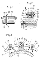
- a tube 10 has a weld seam 20 running in the circumferential direction.
- On one side of the weld seam 20 is a zone of the tube which is thermally stressed or influenced during the welding 10 spanned by a closed link chain 30, 10 segment-shaped intermediate pieces 1 are arranged between the link chain 30 and the tube.
- the link chain 30 consists of outer links 31 and inner links 32, which are held together in an articulated manner by means of pins 33, 37. Every second pin 33 has an eccentric 33 ⁇ in the area of the inner tab 32 and a pin nut 34 at each end. After assembling the link chain 30, the pin nuts 34 are firmly connected to the pins 33 by means of welded seams 35.
- each fixing washer 36 has a hexagonal hole in its center, which fits snugly on the spigot nut 34, so that the fixing washers 36 can be pushed over the spigot nut 34 and fastened to the outer tabs 31 by means of welded seams 35 ⁇ .
- the intermediate pieces 1 are each provided with a trough 3 in which the link chain 30 is supported.
- the pins 37 which have no eccentric, are fixed in the link chain 30 by means of two split pins 38 each.
- the length of the link chain 30 can be varied within wide limits in order to ensure its use in tubes 10 with very different diameters.
- the adjustability of the link chain 30 can additionally be increased by replacing at least part of the eccentric pin 37, pin 33 can be used with eccentrics 33 ⁇ .
- the link chain 30 is now tensioned in such a way that mechanical compressive stresses are generated in this zone which are less than the pressure-breaking strength of the tube 10 in this heat-affected zone are, but cause a deformation beyond the yield point.
- the intermediate pieces 1 bring about an equalization of the compressive stresses.
- the necessary mechanical compressive stresses can also be generated simply by rotating one of the pins 33, the necessary torques to be transferred to the pin 33, e.g. can be generated hydraulically. Good lubrication of the pin 33 is recommended.
- the invention also encompasses embodiments in which, instead of the fastening weld seams 35 ⁇ , e.g. Pins or screws can be used for attaching the fixing washers 36. If self-locking eccentrics are used, there is no need to additionally fix the eccentric position. It is also possible to design at least the pin 33, which is used to generate the final compressive stresses, in such a way that it is provided in one piece with a lever in order to enable large torques to be transmitted. Arranging rolling bearings, e.g. Needle bearings between these pins 33 and the tabs 31, 32 is possible to reduce the friction.
- the fastening weld seams 35 ⁇ e.g. Pins or screws can be used for attaching the fixing washers 36. If self-locking eccentrics are used, there is no need to additionally fix the eccentric position. It is also possible to design at least the pin 33, which is used to generate the final compressive stresses, in such a way that it is provided in one piece with a lever in order to enable large torques to be transmitted
- the method according to the invention can also be applied to other than tubular, cylindrical hollow bodies, such as e.g. on machine housings and on hollow bodies with weld seams that only extend over part of the circumference.
Landscapes
- Engineering & Computer Science (AREA)
- General Engineering & Computer Science (AREA)
- Mechanical Engineering (AREA)
- Heat Treatment Of Articles (AREA)
- Arc Welding In General (AREA)
- Butt Welding And Welding Of Specific Article (AREA)
- Shafts, Cranks, Connecting Bars, And Related Bearings (AREA)
Applications Claiming Priority (2)
| Application Number | Priority Date | Filing Date | Title |
|---|---|---|---|
| CH127387A CH672359A5 (enExample) | 1987-04-02 | 1987-04-02 | |
| CH1273/87 | 1987-04-02 |
Publications (1)
| Publication Number | Publication Date |
|---|---|
| EP0285863A1 true EP0285863A1 (de) | 1988-10-12 |
Family
ID=4206560
Family Applications (1)
| Application Number | Title | Priority Date | Filing Date |
|---|---|---|---|
| EP88104069A Withdrawn EP0285863A1 (de) | 1987-04-02 | 1988-03-15 | Verfahren zum Herabsetzen von Restspannungen in einer Schweissnaht |
Country Status (3)
| Country | Link |
|---|---|
| EP (1) | EP0285863A1 (enExample) |
| JP (1) | JPS63264276A (enExample) |
| CH (1) | CH672359A5 (enExample) |
Citations (2)
| Publication number | Priority date | Publication date | Assignee | Title |
|---|---|---|---|---|
| DE282734C (enExample) * | ||||
| EP0151670A2 (de) * | 1984-02-13 | 1985-08-21 | GebràDer Sulzer Aktiengesellschaft | Vorrichtung zur Bruchverhinderung an einer Rohrleitung |
Family Cites Families (1)
| Publication number | Priority date | Publication date | Assignee | Title |
|---|---|---|---|---|
| DE2827343C2 (de) * | 1978-06-22 | 1983-04-07 | Duewag AG, 4150 Krefeld | Vorrichtung für das Fertigen eines aus Einzelteilen gebildeten Hohlkörpers, insbesondere eines Kessels |
-
1987
- 1987-04-02 CH CH127387A patent/CH672359A5/de not_active IP Right Cessation
-
1988
- 1988-03-15 EP EP88104069A patent/EP0285863A1/de not_active Withdrawn
- 1988-04-01 JP JP8114888A patent/JPS63264276A/ja active Pending
Patent Citations (2)
| Publication number | Priority date | Publication date | Assignee | Title |
|---|---|---|---|---|
| DE282734C (enExample) * | ||||
| EP0151670A2 (de) * | 1984-02-13 | 1985-08-21 | GebràDer Sulzer Aktiengesellschaft | Vorrichtung zur Bruchverhinderung an einer Rohrleitung |
Also Published As
| Publication number | Publication date |
|---|---|
| CH672359A5 (enExample) | 1989-11-15 |
| JPS63264276A (ja) | 1988-11-01 |
Similar Documents
| Publication | Publication Date | Title |
|---|---|---|
| DE2922628C2 (de) | Vorrichtung zum Umwandeln von Wärmeenergie in mechanische Arbeit | |
| DE2938476C2 (enExample) | ||
| DE1511224C3 (de) | Walze mit feststehender hohler Tragachse | |
| DE1648365B2 (de) | Kraftmeßwandler | |
| DE3124877C2 (de) | Einspannvorrichtung für Werkstoffprüfmaschinen zur Durchführung von Wechselspannungs- und Wechseldehnversuchen bei hohen Temperaturen | |
| EP2492517B1 (de) | Verbindungsanordnung für Bambusrohre | |
| DE2239075A1 (de) | Vorrichtung zur befestigung von druckwalzen | |
| EP0525481B1 (de) | Halteeinrichtung für Rohrleitungen, insbesondere für solche in Kraftwerken | |
| CH705267B1 (de) | Vorrichtung zum Befestigen eines Zugelementes, insbesondere eines Zugseils. | |
| EP0285863A1 (de) | Verfahren zum Herabsetzen von Restspannungen in einer Schweissnaht | |
| DE1924716C3 (de) | Verfahren und Vorrichtung zum Beseitigen von Beulen und asymmetrischen Spannungen an der Seitenwand bzw. dem Mantel oder Mantelteil von zylindrischen Behältern aus Metallblech mit festgelegter SoU-Abmessung | |
| DE1958469A1 (de) | Einrichtung zum stirnseitigen Verspannen der Naben von zwei Sektionen eines Gasturbinenrades | |
| DE2455799C3 (de) | Verfahren zum Befestigen und Lösen von in Aufnahmebohrungen angeordneter Stahl-Sitzringe | |
| DE102014224606A1 (de) | Verspannungsanordnung eines ersten Bauteils und eines zweiten Bauteils | |
| DE102013209553A1 (de) | Schraubverbindung mit einem dehnbaren Schaft | |
| DE1922430A1 (de) | Verfahren zum Spannen von Schrauben,insbesondere von Dehnschrauben und Dehnschraube zur Durchfuehrung des Verfahrens | |
| DE3422711C2 (de) | Verfahren zur Befestigung von Tragringen auf der äußeren Wandungsfläche einer Trommel großen Durchmessers | |
| DE1502645B2 (de) | Umfangsschleifscheibe | |
| DE3340817A1 (de) | Pleuel-kolbenanordnung fuer zylinder-kolben-motoren | |
| DE2345610C3 (de) | Matrize zum Strangpressen oder Ziehen | |
| DE3309329C1 (de) | Stab für Sieb-, Förder- oder Roderbänder und Verfahren zu seiner Herstellung | |
| DE1525269B1 (de) | Stock- bzw. holmartiges,straff ausspannbares Geraet | |
| DE3613415C2 (enExample) | ||
| DE600504C (de) | Federnde Befestigung von Isolatoren auf Stuetzen | |
| AT247691B (de) | Verfahren und Vorrichtung zur Herstellung von Kugelgelenklagern sowie nach dem Verfahren hergestelltes Lager |
Legal Events
| Date | Code | Title | Description |
|---|---|---|---|
| PUAI | Public reference made under article 153(3) epc to a published international application that has entered the european phase |
Free format text: ORIGINAL CODE: 0009012 |
|
| AK | Designated contracting states |
Kind code of ref document: A1 Designated state(s): DE ES FR IT SE |
|
| STAA | Information on the status of an ep patent application or granted ep patent |
Free format text: STATUS: THE APPLICATION IS DEEMED TO BE WITHDRAWN |
|
| 18D | Application deemed to be withdrawn |
Effective date: 19890413 |