EP0283985A2 - Commande hydraulique pour un appareil interrupteur à haute tension - Google Patents
Commande hydraulique pour un appareil interrupteur à haute tension Download PDFInfo
- Publication number
- EP0283985A2 EP0283985A2 EP88104445A EP88104445A EP0283985A2 EP 0283985 A2 EP0283985 A2 EP 0283985A2 EP 88104445 A EP88104445 A EP 88104445A EP 88104445 A EP88104445 A EP 88104445A EP 0283985 A2 EP0283985 A2 EP 0283985A2
- Authority
- EP
- European Patent Office
- Prior art keywords
- piston
- fluid
- potential
- control unit
- hydraulic
- Prior art date
- Legal status (The legal status is an assumption and is not a legal conclusion. Google has not performed a legal analysis and makes no representation as to the accuracy of the status listed.)
- Withdrawn
Links
Images


Classifications
-
- H—ELECTRICITY
- H01—ELECTRIC ELEMENTS
- H01H—ELECTRIC SWITCHES; RELAYS; SELECTORS; EMERGENCY PROTECTIVE DEVICES
- H01H33/00—High-tension or heavy-current switches with arc-extinguishing or arc-preventing means
- H01H33/02—Details
- H01H33/28—Power arrangements internal to the switch for operating the driving mechanism
- H01H33/30—Power arrangements internal to the switch for operating the driving mechanism using fluid actuator
- H01H33/34—Power arrangements internal to the switch for operating the driving mechanism using fluid actuator hydraulic
-
- H—ELECTRICITY
- H01—ELECTRIC ELEMENTS
- H01H—ELECTRIC SWITCHES; RELAYS; SELECTORS; EMERGENCY PROTECTIVE DEVICES
- H01H9/00—Details of switching devices, not covered by groups H01H1/00 - H01H7/00
- H01H2009/0083—Details of switching devices, not covered by groups H01H1/00 - H01H7/00 using redundant components, e.g. two pressure tubes for pressure switch
-
- H—ELECTRICITY
- H01—ELECTRIC ELEMENTS
- H01H—ELECTRIC SWITCHES; RELAYS; SELECTORS; EMERGENCY PROTECTIVE DEVICES
- H01H33/00—High-tension or heavy-current switches with arc-extinguishing or arc-preventing means
- H01H33/02—Details
- H01H33/027—Integrated apparatus for measuring current or voltage
-
- H—ELECTRICITY
- H01—ELECTRIC ELEMENTS
- H01H—ELECTRIC SWITCHES; RELAYS; SELECTORS; EMERGENCY PROTECTIVE DEVICES
- H01H33/00—High-tension or heavy-current switches with arc-extinguishing or arc-preventing means
- H01H33/02—Details
- H01H33/42—Driving mechanisms
- H01H33/423—Driving mechanisms making use of an electromagnetic wave communication
Definitions
- the invention relates to a hydraulic drive according to the preamble of claim 1.
- High-voltage circuit breakers are actuated, inter alia, by hydraulic drives which have a piston-cylinder arrangement, of which the piston is connected or coupled to the movable contact piece of the power switching device.
- the hydraulic drive is usually outside the metal encapsulation or outside the switch pole, and it is usually arranged at earth potential; the connection between the piston rod and the movable switch contact piece of the circuit breaker is made by means of insulating drive rods and, if necessary, further mechanical transmission elements. All of these transmission elements must be designed in such a way that the switching pin can be accelerated and braked without play. As a result, the design effort for such a circuit breaker is relatively high.
- the object of the invention is to provide a hydraulic drive of the type mentioned, in which the mechanical design effort is reduced.
- the piston-cylinder arrangement is at high voltage potential, as is the energy store, and only the control pulses for the drive and the processing of the signals coming from the drive, which, for example, indicate the switch position, are processed at ground potential.
- this reduces the expenditure on equipment for the drive, because relatively long transmission rods made of insulating material can be omitted, and, on the other hand, the size of the switching device is considerably reduced. It is no longer necessary to connect the entire drive housing to a separately provided connection flange.
- E SH energy of the switching action
- M1 moving mass of the drive
- M2 moving mass of the transmission linkage
- M3 moving mass of the switch (switch contact piece, blow piston ect.)
- E L energy of the arc solution.
- the hydraulic drive is at high voltage potential and the distance from the piston to the switching contact piece is thereby considerably reduced.
- the transmission linkage can be omitted and M2 become 0.
- the low energy to be supplied by the drive allows a smaller design, so that M1 is reduced.
- the hydraulic drive can be further reduced and thus improved.
- the electronic control unit which is used to control hydraulic actuators (valves) and the drive piston, is also arranged at high voltage potential, so that long control paths are advantageously eliminated.
- the signals supplied to the control unit or the signals coming from the control unit are, according to the characterizing features of claim 3 and claim 4, light signals which are supplied to or removed from the control unit via fiber optic cables or by a direct light beam, the operating energy being light energy is transmitted and converted into electrical energy by means of a photocell arrangement and either directly to operate the control unit or to charge an electrical storage device (Accumulator) is used, the energy content of which in turn is then used for the electrical supply to the control unit.
- an electrical storage device Accelulator
- a central control device can be provided which, according to the characterizing feature of claim 5, is at earth potential and is coupled to the control unit via light signals.
- a compressor unit is therefore provided at earth potential, which is connected to the piston-cylinder arrangement or the fluid storage arrangement via electrically insulating, pressure-resistant hydraulic lines.
- the control unit is arranged at high voltage potential, which, like the valves, requires electrical energy which is to be taken from a battery or accumulator, as mentioned above, which is at high voltage potential, or which is via optical glass fiber lines or via direct emitted light is charged with a downstream photovoltaic element.
- an electrical generator at high voltage potential can preferably be spatially closely associated with the movable contact piece, which is also by means of a high voltage potential which isolates it from the earth potential to the high voltage potential
- High pressure lines pumped hydraulic fluid driven hydraulic motor is driven and thereby charges the electrical storage. It is thereby achieved that, if necessary, larger energies can be transported from earth potential to high voltage potential more easily with the aid of hydraulic lines than with optical glass fiber lines.
- an accumulator with a higher capacity can be used or it is possible to charge the battery in a shorter time than in the known embodiment.
- the same pressure fluid can be used as that used to actuate the contact piece of the switching device, i. that is, with which the hydraulic accumulators are charged.
- the pump at ground potential could also be supplemented redundantly by a second pump which has the same output as the main pressure fluid pump; this second pump can also be designed so that it is just sufficient to drive the hydraulic motor.
- the drive is directly spatially assigned to the circuit breaker contact, it is divided into one drive for each phase.
- the actuation of the “partial drives” for each phase can be adapted to the phase position of the current in the associated conductor.
- the energy required for synchronous switching in accordance with the phase position is significantly less than that which is to be provided if the switch has to switch independently of the phase position. So that the compression or gas piston can be made smaller and accordingly the mass to be accelerated M3 of the switch is reduced in the above formula.
- the switch drive becomes smaller because it is spatially assigned to the switch contact pin and is at the same potential with it, and vice versa, it can be placed there because it has become smaller.
- a waveguide 11 located at high voltage potential, which is held within the metal encapsulation 10 by means of a disk-shaped support insulator 12.
- This post insulator 12 can of course also be a partition insulator.
- the waveguide 11 has an area 13 of enlarged diameter, in which a drive unit 14 is accommodated.
- a drive unit 14 With this drive unit 14, a movable switching contact piece 15 is driven, which interacts with a fixed switching contact piece 16 and thus forms a high-voltage circuit breaker.
- the drive unit 14 has a piston-cylinder arrangement 17, the piston 18 of which is coupled to the movable switching contact piece 15.
- Inside the drive unit 14 there are also storage spaces 19 for pressurized fluid, with which the piston-cylinder arrangement 17 is actuated or driven in order to bring the movable switch contact piece into the switch-on or switch-off position.
- 2 storage spaces are provided for switching on or switching off in the arrangement according to FIG. 1. Both the piston-cylinder arrangement and the storage spaces 19 are actuated by means of electrically operated valves 20.
- control unit 21 In the interior of the waveguide 11 and approximately in the region 13 with an enlarged diameter, there is a control unit 21, the output signals of which are fed to the drive unit 14 via a line 22 in order to control the valves 20.
- electrical store 23 In the interior of the waveguide 11 there is also an electrical store 23, which is designed as a battery and supplies the control unit 21 with electrical energy via a line 24.
- the drive unit 14 is a unitary block in which all the components required for actuating the movable contact piece 15 are combined.
- the charging of the electrical memory 23 is effected by a supply unit 25, which supplies an optical transmitter unit 26 via a line 27, in which optical transmitter unit 26 light is generated which is supplied via the beam path 28 to a photocell 29, in which the light energy is converted into electrical energy converted and fed to the electrical storage 23 via a line 30.
- a central control module 31 At ground potential is a central control module 31, from which control signals are supplied to the control unit 21 via a glass fiber line 32 and which is also connected to the compressor unit 33 and the feed unit 25 via the lines 36, 37.
- a compressor unit 33 at earth potential which is supplied to the drive unit 14 via a pressure-resistant hydraulic line 34 and pressurized fluid, and there to the storage spaces 19.
- a return line 35 runs parallel to this and is used to return used fluid from the storage spaces 19 or the piston-cylinder arrangement 17 to the compressor unit.
- the supply line 34 as well as the return line 35 and the control line 32 are guided through the post insulator 12 from earth potential to high voltage potential.
- FIG. 2 shows an advantageous embodiment of the switch according to FIG. 1.
- a current sensor 38 is arranged around the waveguide 11 and is connected to the control unit 21 via a connecting line 39. This arrangement of the attachment of the current sensor 38 to the conductor 11 makes it possible for the actuation of the drive piston 18 triggered by the control unit 21 to be synchronized with the current profile, so that the switching device according to FIG. 2 is a synchronous switch.
- a Rogowski coil can be used as the current sensor 38, as described in the parallel application (E No. 4697).
- FIGS. 1 and 2 The configuration or attachment of the drive according to the invention to the high-voltage conductor has been described in FIGS. 1 and 2 using an SF incas-gas-insulated, metal-encapsulated switch.
- the inventive idea can also be used in an outdoor switching device.
- This outdoor switching device has a base part 40 on which a support insulator 41 is fastened and constructed, which supports the switching unit 42 or isolates it from earth potential.
- the switching unit consists of a first housing 43, to which an insulating intermediate piece 44 is connected, which is tubular and extends transversely to the longitudinal axis of the supporting insulator, an end cover made of electrically conductive material 45 being fastened to the free end face of the insulating intermediate piece.
- a fixed contact piece 46 and a movable contact piece 47 are provided in the end cover 45, the latter being connected to a hydraulic drive unit 48 which has a piston-cylinder arrangement 49, on the piston 50 of which piston the movable contact piece 47 is coupled.
- control unit 51 In the interior of the housing 43 there is a control unit 51 corresponding to the control unit 21, which is fed or supplied by a battery unit 52, which corresponds to the battery unit 23. At ground potential there is a compressor unit 53 which is connected to the drive unit 48 via a supply line 54 and a return line 55.
- a central control module 56 controls the control unit 51 and by means of an energy supply device 57 the battery 52 is supplied with energy via an optical fiber line 58; the unit 57 emits light, which is converted into electrical current by a photocell in the battery unit 52.
- the line 59, via which the central control device 56 controls the control unit 51, is also designed as an optical fiber line.
- the fluid lines 54, 55 and the glass fiber lines 58, 59 provided for the transmission of the control energy and the control information are routed within a supply line 60 running parallel to the post insulator 41.
- the assembly outlay can be advantageously reduced in particular if the support insulator 41 is subdivided at higher voltage levels and if the support insulator is possibly only mounted on the switching unit 42 at the construction site.
- the drive described above with several separate storage spaces that are matched in number to the number of switching operations required, can of course also be arranged at high voltage potential, because due to its close proximity to the movable contact piece and the resulting smaller design, it has sufficient space for actuating smaller masses has high voltage potential.
- the energy for charging the battery takes place via the glass fiber lines or via direct light radiation.
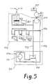
- the elements of the circuit breaker drive according to the invention are combined in two main blocks 111 and 110, one of which 111 is at ground potential and the other 110 is at high voltage potential.
- the two blocks 110 and 111 are connected to one another via two electrically insulating high-pressure hydraulic lines 112 and 113.
- a pump 114 and a low-pressure container 115 are accommodated in the main block 111, which is at ground potential. With the help of the pump 114, pressurized fluid can be transported to high-voltage potential via the high-pressure hydraulic line 112, and there depending on the position Reusable valve 116 either drive the hydraulic motor 117 or serve to charge one of the storage spaces 118, 119 and 120.
- the hydraulic motor 117 is connected via a shaft 123 to a generator 124 connected, which is used for electrical recharging of a battery 125.
- two pumps 114 and 114a can be arranged in the main block 111, which is at earth potential, each of which is adapted to the different requirements when reloading the storage spaces 118, 119 and 120 on the one hand and the drive of the hydraulic motor 117 on the other hand, or they are designed redundantly to increase the device reliability are. Considerations for increasing reliability through redundant execution of individual elements can of course be extended to other elements.
- An alternator the size of which is small and which can then be assigned to block 110, which is at high voltage potential, can preferably be used as the generator.
Landscapes
- Driving Mechanisms And Operating Circuits Of Arc-Extinguishing High-Tension Switches (AREA)
- Valve Device For Special Equipments (AREA)
- Fluid-Pressure Circuits (AREA)
- Gas-Insulated Switchgears (AREA)
Applications Claiming Priority (4)
| Application Number | Priority Date | Filing Date | Title |
|---|---|---|---|
| DE19873710082 DE3710082C2 (de) | 1987-03-27 | 1987-03-27 | Hydraulischer Antrieb für ein Hochspannungsschaltgerät |
| DE3710082 | 1987-03-27 | ||
| DE19873718869 DE3718869A1 (de) | 1987-06-05 | 1987-06-05 | Hydraulischer antrieb fuer ein hochspannungsschaltgeraet |
| DE3718869 | 1987-06-05 |
Publications (2)
| Publication Number | Publication Date |
|---|---|
| EP0283985A2 true EP0283985A2 (fr) | 1988-09-28 |
| EP0283985A3 EP0283985A3 (fr) | 1990-07-11 |
Family
ID=25853963
Family Applications (1)
| Application Number | Title | Priority Date | Filing Date |
|---|---|---|---|
| EP19880104445 Withdrawn EP0283985A3 (fr) | 1987-03-27 | 1988-03-21 | Commande hydraulique pour un appareil interrupteur à haute tension |
Country Status (4)
| Country | Link |
|---|---|
| US (1) | US4849650A (fr) |
| EP (1) | EP0283985A3 (fr) |
| JP (1) | JPS63252331A (fr) |
| DE (1) | DE3710082C2 (fr) |
Cited By (1)
| Publication number | Priority date | Publication date | Assignee | Title |
|---|---|---|---|---|
| RU2148280C1 (ru) * | 1998-09-30 | 2000-04-27 | Комбинат "Электрохимприбор" | Гидравлический привод для силового высоковольтного выключателя |
Families Citing this family (7)
| Publication number | Priority date | Publication date | Assignee | Title |
|---|---|---|---|---|
| JP2549170B2 (ja) * | 1989-04-24 | 1996-10-30 | 株式会社日立製作所 | 柱上用開閉器 |
| DE3929808A1 (de) * | 1989-09-07 | 1991-03-21 | Gema Ransburg Ag | Automatische erdungseinrichtung einer elektrostatischen spruehbeschichtungsanlage |
| DE4022262A1 (de) * | 1990-07-12 | 1992-01-16 | Siemens Ag | Verfahren zum betrieb eines leistungsschalters |
| RU2141146C1 (ru) * | 1998-04-23 | 1999-11-10 | Российский Федеральный Ядерный Центр - Всероссийский Научно-Исследовательский Институт Экспериментальной Физики | Способ контроля и управления гидроприводом |
| JP4351811B2 (ja) * | 2001-03-22 | 2009-10-28 | 株式会社東芝 | タンク型真空遮断器 |
| USD711839S1 (en) * | 2012-07-03 | 2014-08-26 | Abb Ag | Hydraulic drive for high-voltage circuit breaker |
| EP2701280A1 (fr) * | 2012-08-24 | 2014-02-26 | ABB Technology AG | Alimentation électrique auxiliaire pour des applications haute tension |
Family Cites Families (18)
| Publication number | Priority date | Publication date | Assignee | Title |
|---|---|---|---|---|
| US2783338A (en) * | 1955-09-21 | 1957-02-26 | Gen Electric | Operating mechanism for a fluid-blast circuit breaker |
| US3075060A (en) * | 1957-10-30 | 1963-01-22 | Westinghouse Electric Corp | Circuit interrupters |
| DE1256296B (de) * | 1958-01-16 | 1967-12-14 | Westinghouse Electric Corp | Hydraulischer Antrieb fuer einen elektrischen Leistungsschalter |
| FR1352178A (fr) * | 1962-12-04 | 1964-02-14 | Comp Generale Electricite | Perfectionnements aux dispositifs de commande oléopneumatique de disjoncteurs devant effectuer des manoeuvres successives pendant un court laps de temps |
| US3500723A (en) * | 1965-02-16 | 1970-03-17 | Westinghouse Electric Corp | Hydraulic systems with increased speed of response |
| US3454734A (en) * | 1965-09-22 | 1969-07-08 | Westinghouse Electric Corp | Compressed-gas circuit interrupter |
| DE1807592A1 (de) * | 1968-04-19 | 1970-01-29 | Liebknecht Transformat | Hochspannungsschalter |
| DE1807590A1 (de) * | 1968-04-19 | 1969-11-06 | Liebknecht Transformat | Betaetigungseinrichtung fuer Hochspannungsschalter |
| DE1807591A1 (de) * | 1968-11-07 | 1969-11-06 | Liebknecht Transformat | Steuerungssystem fuer Hochspannungsschalter |
| DE2003095A1 (de) * | 1969-02-07 | 1970-08-27 | Liebknecht Transformat | Einrichtung zur Betaetigung von Hochspannungsschaltern |
| US3646292A (en) * | 1970-05-11 | 1972-02-29 | Gen Electric | High-voltage electric circuit breaker with high-speed tripping means |
| DE2063093C3 (de) * | 1970-12-11 | 1976-01-08 | Siemens Ag, 1000 Berlin Und 8000 Muenchen | Hochspannungsschalter |
| US3885113A (en) * | 1973-10-19 | 1975-05-20 | Gen Electric | Control for an electric circuit breaker with valve and piston operating means |
| FR2272477B1 (fr) * | 1974-05-22 | 1978-06-16 | Gratzmuller J | |
| DE2631194B2 (de) * | 1976-07-10 | 1979-03-08 | Friedhelm Dipl.-Ing. 4630 Bochum Caspers | Anordnung zur Zuführung von Versorgungsenergie an ein MeB- und Nachrichtengerät in einer Hochspannungsanlage |
| DE2901872A1 (de) * | 1979-01-18 | 1980-07-31 | Siemens Ag | Hochspannungsisoliereinrichtung, insbesondere isolator mit einem lichtleiter |
| US4413166A (en) * | 1981-03-19 | 1983-11-01 | Westinghouse Electric Corp. | Disconnect switch |
| US4610033A (en) * | 1984-12-14 | 1986-09-02 | Harvey Hubbell Incorporated | Insulator with fiber optic communication channel |
-
1987
- 1987-03-27 DE DE19873710082 patent/DE3710082C2/de not_active Expired - Fee Related
-
1988
- 1988-03-21 EP EP19880104445 patent/EP0283985A3/fr not_active Withdrawn
- 1988-03-23 JP JP63069228A patent/JPS63252331A/ja active Pending
- 1988-03-28 US US07/174,086 patent/US4849650A/en not_active Expired - Fee Related
Cited By (1)
| Publication number | Priority date | Publication date | Assignee | Title |
|---|---|---|---|---|
| RU2148280C1 (ru) * | 1998-09-30 | 2000-04-27 | Комбинат "Электрохимприбор" | Гидравлический привод для силового высоковольтного выключателя |
Also Published As
| Publication number | Publication date |
|---|---|
| JPS63252331A (ja) | 1988-10-19 |
| US4849650A (en) | 1989-07-18 |
| DE3710082C2 (de) | 1994-05-19 |
| EP0283985A3 (fr) | 1990-07-11 |
| DE3710082A1 (de) | 1988-10-06 |
Similar Documents
| Publication | Publication Date | Title |
|---|---|---|
| DE69903422T2 (de) | Betriebsteuerungsvorrichtung für elektrische schaltanlage | |
| EP0291762B1 (fr) | Installation de commutation polyphasée haute tension blindée à isolation gazeuse | |
| DE69929229T2 (de) | Gasisolierte schaltvorrichtung | |
| DE69905065T2 (de) | Gasisolierte schaltvorrichtung | |
| EP0735637A2 (fr) | Dispositif de coupure ayant un caiter métallique mis à la terre et rempli d'un gaz isolant | |
| DE3915948A1 (de) | Lastschaltanlage mit einem dreistellungsschalter | |
| DE19929572A1 (de) | Magnetischer Linearantrieb | |
| DE69903049T2 (de) | Betriebsteuerungsvorrichtung für hoch oder mittelspannungschaltgerät | |
| EP0283985A2 (fr) | Commande hydraulique pour un appareil interrupteur à haute tension | |
| WO2015082280A1 (fr) | Commutateur d'isolation et/ou de mise à la terre triphasé pour une installation de commutation triphasée isolée par gaz | |
| EP0812462B1 (fr) | Commande a accumulation d'energie pour un pole d'interrupteur de puissance haute tension rempli de gaz isolant | |
| DE2111121C3 (de) | Gasentladungsschaltröhre | |
| DE1615634B2 (de) | Schalter zum schnellen Kurzschließen von elektrischen Apparaten | |
| DE19815538A1 (de) | Antriebseinrichtungen für Unterbrechereinheiten von Schaltgeräten zur Energieversorgung und -verteilung | |
| EP0996135A2 (fr) | Dispositif de commande pour le contact mobile d'un interrupteur électrique | |
| DE4320906C2 (de) | Gehäuse für einen druckgasisolierten Hochspannungs- Leistungs-Schalter | |
| DE19533794A1 (de) | Metallgekapselter, gasisolierter Hochspannungsschalter | |
| DE2636410A1 (de) | Schalteinrichtung fuer mittelspannungskabelnetze | |
| DE60132164T2 (de) | Kombinierte Antriebvorrichtung durch Flüssigkeitsdruck | |
| EP1164610A1 (fr) | Installation de commutation à haute tension | |
| DE19807777C1 (de) | Schaltfeld für eine gasisolierte Schaltanlage mit liegenden Leistungsschaltern und einer einseitig zu einer vertikalen Strombahn angeordneten dreiphasig gekapselten Doppelsammelschiene | |
| DE1958837A1 (de) | Metallgekapselte Hochspannungsschaltanlage | |
| DE1807591A1 (de) | Steuerungssystem fuer Hochspannungsschalter | |
| DE19837009A1 (de) | Antrieb für das bewegliche Kontaktstück eines Hochspannungsleistungsschalters | |
| EP0253053A1 (fr) | Générateur d'ondes de choc pour un dispositif de désintégration à distance des concrétions dans un organisme vivant |
Legal Events
| Date | Code | Title | Description |
|---|---|---|---|
| PUAI | Public reference made under article 153(3) epc to a published international application that has entered the european phase |
Free format text: ORIGINAL CODE: 0009012 |
|
| AK | Designated contracting states |
Kind code of ref document: A2 Designated state(s): CH DE FR GB IT LI SE |
|
| RAP1 | Party data changed (applicant data changed or rights of an application transferred) |
Owner name: ASEA BROWN BOVERI AKTIENGESELLSCHAFT |
|
| PUAL | Search report despatched |
Free format text: ORIGINAL CODE: 0009013 |
|
| AK | Designated contracting states |
Kind code of ref document: A3 Designated state(s): CH DE FR GB IT LI SE |
|
| STAA | Information on the status of an ep patent application or granted ep patent |
Free format text: STATUS: THE APPLICATION IS DEEMED TO BE WITHDRAWN |
|
| 18D | Application deemed to be withdrawn |
Effective date: 19910112 |