EP0735637A2 - Dispositif de coupure ayant un caiter métallique mis à la terre et rempli d'un gaz isolant - Google Patents
Dispositif de coupure ayant un caiter métallique mis à la terre et rempli d'un gaz isolant Download PDFInfo
- Publication number
- EP0735637A2 EP0735637A2 EP96810139A EP96810139A EP0735637A2 EP 0735637 A2 EP0735637 A2 EP 0735637A2 EP 96810139 A EP96810139 A EP 96810139A EP 96810139 A EP96810139 A EP 96810139A EP 0735637 A2 EP0735637 A2 EP 0735637A2
- Authority
- EP
- European Patent Office
- Prior art keywords
- busbar
- switching device
- power connection
- circuit breaker
- metal housing
- Prior art date
- Legal status (The legal status is an assumption and is not a legal conclusion. Google has not performed a legal analysis and makes no representation as to the accuracy of the status listed.)
- Granted
Links
Images


Classifications
-
- H—ELECTRICITY
- H02—GENERATION; CONVERSION OR DISTRIBUTION OF ELECTRIC POWER
- H02B—BOARDS, SUBSTATIONS OR SWITCHING ARRANGEMENTS FOR THE SUPPLY OR DISTRIBUTION OF ELECTRIC POWER
- H02B13/00—Arrangement of switchgear in which switches are enclosed in, or structurally associated with, a casing, e.g. cubicle
- H02B13/02—Arrangement of switchgear in which switches are enclosed in, or structurally associated with, a casing, e.g. cubicle with metal casing
- H02B13/035—Gas-insulated switchgear
-
- H—ELECTRICITY
- H01—ELECTRIC ELEMENTS
- H01H—ELECTRIC SWITCHES; RELAYS; SELECTORS; EMERGENCY PROTECTIVE DEVICES
- H01H31/00—Air-break switches for high tension without arc-extinguishing or arc-preventing means
- H01H31/003—Earthing switches
Definitions
- the invention is based on a switching device according to the preamble of claim 1.
- This switching device has a grounded, insulating gas-filled metal housing, which accommodates a power switch and an earthing switch. At least one power connection to at least one busbar and one power connection to a consumer outlet, for example to a line or a cable, are led through the wall of the metal housing.
- Such a switching device has smaller dimensions than a correspondingly acting outdoor switching device, since the dielectric strength of the metal housing increases the dielectric strength against air.
- the invention relates to a prior art of switching devices as known from DE-PS 951 019 and DE 27 54 691 C2.
- the switching device described in DE-PS 951 019 has a housing filled with an insulating gas with a higher dielectric strength than air, in which switches such as circuit breakers, output isolating switches, measuring transducers and bushings are contained. Furthermore, all devices for actuating the switches and all fuses and monitoring devices are accommodated in the housing, so that the switching device represents a ready-to-use switching unit which only needs to be connected to the busbars and the control lines at the place of use.
- the busbars and the associated ones Busbar isolators are arranged in a further housing filled with insulating gas. To connect the switching device, therefore, a connecting channel, which is also filled with insulating gas, is required, which is installed between the switching device and the busbar housing.
- the switching device described in DE 27 54 691 C1 is part of a metal-encapsulated, pressurized gas-insulated high-voltage switchgear and has a pressure vessel filled with SF 6 of several bar pressure, in which, in addition to the circuit breaker, current transformers and working earth electrodes are arranged and in which different connections of these are connected by field-specific current-carrying parts Devices can be produced one below the other.
- the pressure vessel is positively connected to two further SF 6 -filled pressure vessels, one of which contains all devices and current-carrying parts required on the connection side, such as disconnectors, cable or overhead line connection elements and earth electrodes, and the other contains all switching devices and current-carrying parts belonging to the busbar .
- Such a switching device achieves high operational availability in a gas-insulated high-voltage switchgear in which the busbar part and the outgoing part are each accommodated in separate compressed gas containers, with the smallest possible number of pressure containers.
- a high-voltage circuit breaker described in DE 33 18 344 A1 has a switching unit arranged in a grounded metal housing filled with insulating gas, the two current connections of which are led through the wall of the metal housing to overhead lines.
- two disconnection points are arranged, which can be actuated by the assembly personnel after the insulating gas has been released and the metal housing has been opened, and are used to disconnect and connect the power connections during the disassembly and assembly of the switching unit.
- this switch and all other switchgear elements are assembled component by component.
- the invention has for its object to provide a switching device of the type mentioned, which is characterized by a more compact design and higher availability than a comparable-acting outdoor switching device and with which a variety of circuit configurations between one or several busbars located in the open air and a consumer outlet, such as a cable or an overhead line, can be formed.
- the switching device according to the invention is characterized in that the majority of all switching devices required in a high-voltage switchgear, such as circuit breakers, busbar disconnectors and earth electrodes, are accommodated in a single bulkhead-free gas space of a predominantly tubular metal housing.
- a switching device can be prefabricated and tested as a whole self-contained module in the factory.
- a high-voltage switchgear can then be completed on site in an extremely quick and simple manner by connecting a power connection led from the switching device to the busbar (s) and a further power connection led out of the switching device to a cable or an overhead line.
- the switching devices of the high-voltage system are no longer exposed to the direct influence of the weather and are therefore highly available even after long, switch-free periods.
- several foundations assigned to the individual components are no longer required for all the essential components of the system, but a single foundation supporting the switching device is generally sufficient.
- the switching device Since the switching device has small insulation distances because of the insulating gas provided in the interior of its metal housing, it is small and space-saving and can easily be used as a replacement for several in one or more branches one or more busbars provided switchgear can be installed in any existing outdoor switchgear. Because of the small spatial dimensions, the switching device according to the invention can be easily installed in all common switchgear layouts.
- the switching device according to the invention is particularly advantageously suitable for retrofitting existing outdoor switchgear with small dimensions. By installing the switching device according to the invention, such systems can be expanded particularly easily and inexpensively to a higher voltage level.
- additional switching devices such as outgoer isolators or further earth electrodes, and / or sensors, such as, in particular, capacitive or optically acting voltage sensors and Rogowski coil designed or optically acting current sensors and / or a current and voltage sensor combining both sensors, can be used in the Switching device may be provided. Since such sensors, in contrast to conventional current and / or voltage converters, are designed to be extremely space-saving, the switchgear according to the invention can easily be retrofitted with additional current and / or voltage sensors, which then, for example, the voltage measurement required for synchronized and controlled switch-on operations on both Allow sides of the switch.
- the metal housing expediently has a housing of defined dimensions for each voltage class. It is advisable to choose the dimensions so that the metal housing can accommodate circuit breakers, busbar disconnectors and earth electrodes as well as outgoer disconnectors and sensors. The metal housing can then contain all of these components or only a part of these components as required.
- the switching device according to the invention is used, for example, to retrofit an outdoor switchgear assembly in which functional current and / or voltage converters and outgoing disconnectors are still present, so it is sufficient if the metal housing includes circuit breakers, busbar disconnectors and earth electrodes, and if the current and voltage transformers that are still present are attached to the bushings when the high-voltage switchgear is installed and the outgoing disconnector that is still present is connected to the switchgear outlet.
- the switching device can be installed in systems with a single busbar as well as in systems with a double busbar.
- a particularly space-saving arrangement is achieved if, when using the switching device according to the invention in a switchgear assembly with a double busbar, the busbar isolator is designed as a multiple position isolator and can switch from one busbar to the other busbar without interruption.
- one of the two outdoor feedthroughs can be removed and the flange attachment on the metal housing and used to hold the outdoor feedthrough can be closed by an earthed metal cover a fixed contact of the busbar disconnector, which acts as a grounding contact, is attached to the inside of the housing.
- the switching device according to the invention can be encapsulated both single-phase and multi-phase.
- the switching device shown in FIGS. 1 and 2 and identified by the reference numeral 1 has an essentially tubular metal housing 2 filled with insulating gas, such as SF 6 of a few bar pressure.
- the metal housing 2 is mounted on a frame (not shown) and is at earth potential.
- the metal housing has three non-visible openings on its surface, which are each limited by one of three tubular flange lugs 3, 4 and 5.
- One of three outdoor bushings 6, 7 and 8 is held at the ends of the flange attachments facing away from the metal housing 2.
- These outdoor bushings preferably each have a fiber-reinforced plastic housing with a silicone shield.
- the switching device is not only considerably lighter and therefore easier to transport compared to a device equipped with porcelain insulators, but at the same time the risk of an explosion of the bushings, for example as a result of assembly or maintenance work in the system or under the influence of breaking forces, is practically eliminated.
- the axes of the flange lugs 3, 4 and 5 are typically at an angle of approximately 50 ° on the pipe axis of the metal housing 2.
- the flange lugs 4 and 5 are inclined towards one another by an angle of typically 80 to 100 °. Due to the angled arrangement of the flange attachments, the required dielectric strength in air can be achieved with the smallest possible housing dimensions.
- the metal housing 2 has two further, likewise not visible, openings on its two end faces.
- a drive 9 for a circuit breaker located in the interior of the metal housing is guided through one opening and a drive 10 for a busbar disconnector also located inside the housing is passed through the other opening in a gas-tight manner.
- the metal housing 2 On its outer surface, the metal housing 2 has a further opening, which cannot be seen, through which a drive 11 for an earth electrode located in the metal housing 2 is guided in a gas-tight manner.
- the metal housing 2 of the switching device receives a circuit breaker 12, one of which has a power connection via a busbar isolator 13 designed as a multi-position isolator and one of the two outdoor bushings 7 or 8 with a busbar SS1 or SS2 of a high-voltage switchgear and its other Power connection via the outdoor bushing 6 with a consumer outlet, approximately a cable or line L of the high-voltage switchgear.
- the metal housing 3 also accommodates an earth electrode 14 connected between the output-side power connection of the circuit breaker 12 and the grounded metal housing 2, as well as sensors, such as a current sensor 15 and a voltage sensor 16, which detect the current and the voltage at the consumer-side power connection of the power switch 12.
- the sensors 15, 16 are designed to save space.
- the current sensor 15 can be designed as a Rogowski coil or optical sensor, the voltage sensor 16 as a capacitive voltage divider or optical sensor. Alternatively, the two sensors can be combined in a single sensor.
- the outdoor bushing 8 can alternatively be omitted and the circuit breaker 12 can be connected to only one busbar SS of the high-voltage switchgear via a busbar isolator 13 designed as a 2-position isolator and the outdoor bushing 7.
- a busbar isolator 13 designed as a 2-position isolator and the outdoor bushing 7.
- an earthing switch 17 connected between the busbar-side power connection of the circuit breaker 12 and the grounded metal housing 2 and / or an output isolator 18 and / or a further voltage sensor 19 and a further current sensor 20 connected between the output-side power connection of the circuit breaker and the current conductor of the outdoor bushing 6 be provided.
- the sensors 19, 20 detect current and voltage at the busbar-side power connection of the circuit breaker 12. Together with the sensors 15, 16, differential currents and / or voltages can thus be determined via the circuit breaker 12, which enables a possibly desired synchronous switching of the circuit breaker.
- Housing voltage and current sensors and other sensors for example for measuring pressure, density or temperature or partial discharges, in a single housing saves housing bushings and at the same time the distances required to transmit the information determined by the sensors can be kept short.
- are through the compact design also accommodates all the connections required for the control and regulation of the switching devices of the switching device 1 for the exchange of information between the sensors and the switching devices in a short and central place. To fulfill its I&C functionality, it is therefore only necessary to connect the switching device 1 in a simple manner to a control cabinet which performs I&C tasks.
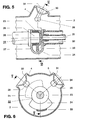
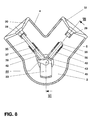
- FIG. 5 A constructively designed part of the switching device according to Figure 1 is shown in Figures 5 and 6.
- sections through the metal housing 2 of the switching device 1 in the region of the two flange attachments 4 and 5 are shown after the two outdoor bushings 7 and 8 have been removed.
- the section shown in Figure 5 is carried out along the axis of the tubular metal housing 2, whereas the section shown in Figure 6 is carried out essentially transversely to the axis.
- 21 denotes a shaft, which is made gas-tight from the metal housing 2 and consists of insulating material, of the drive 10 of the busbar disconnector 13 shown in FIGS. 1 and 2.
- the movable contact arrangement 22 is constructed from a bearing bush 23 and a circular sector-shaped section 24, which is attached to the bearing bush and extends radially outwards.
- the bearing bush 23 is rotatably supported on a cylindrical end section 25 of a fixed power connection 26 of the circuit breaker 12 arranged on the busbar side.
- a slide contact 27 serving for the current transmission from the busbar disconnector 13 to the circuit breaker 12 is arranged.
- the reference numerals 28 and 29 denote fixed contacts of the busbar disconnector 13, which are held by support insulators 30 and 31 in the region of the flange extensions 4 and 5.
- the support insulators 30 and 31 can be designed as partition insulators, which seal the inside of the metal housing 2 gas-tight to the outside. However, they are preferably designed as gas-permeable post insulators. Insulating gas from the interior of the metal housing then forms a total volume at the same pressure level with the interior of the gas-tight outdoor bushings 7 and 8.
- a support insulator 32 fastened on the end face of the metal housing 2 concentrically surrounds the shaft 21 and carries at its end facing away from the metal housing 2 a bracket-shaped holding part 33 which engages behind the movable contact arrangement 22 and on which the busbar-side power connection 26 of the circuit breaker 12 is supported.
- the power connection 26 of the circuit breaker 12 can also be supported on an insulator mounted on the inner lateral surface of the metal housing 2. The shaft 21 can then be guided into the interior of the housing via an opening provided on the outer surface of the metal housing 2.
- the movable contact arrangement of the busbar disconnector 13 can have four preferred positions:
- the section 24 contacts the fixed contact 28 and has thus connected the busbar SS1 to the power connection of the circuit breaker 12 on the busbar side. With the circuit breaker 12 closed, the busbar SS1 now feeds into the load outlet L.
- a second position (not shown in FIG. 6) can be achieved by rotating the shaft 21 clockwise.
- the section 24 shaped as a sufficiently large circular sector can additionally contact the fixed contact 29 without the galvanic connection between the busbar SS1 and the movable contact arrangement 22 being interrupted.
- the two busbars SS1 and SS2 are then connected to one another via the busbar disconnector 13.
- a third position can be reached (also not shown in FIG. 6).
- the fixed contact 28 and the movable contact arrangement 22 separate from one another and now only the fixed contact 29 and thus the busbar SS2 are connected to the busbar-side power connection 26 of the circuit breaker 12.
- the busbar SS2 is now connected to the load outlet L.
- the flange extension 5 can carry a metal cover 34 shown in dashed lines in FIG. 6, on the side of which is directed into the interior of the housing and is now attached to the fixed contact 29 of the busbar disconnector 13 which acts as a ground contact.
- the busbar disconnector 13 Then, in the second position, the busbar SS1 and at the same time the busbar-side power connection 26 of the circuit breaker 12 are grounded. In the third position, he only grounds the power connection 26 of the circuit breaker.
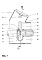
- FIGS. 7 and 8 show a busbar disconnector 13 which is modified compared to the busbar disconnector shown in FIGS. 5 and 6.
- the movable contact part 22 of this busbar disconnector does not have a rotatable, sector-shaped section 24 made of contact material, but a contact part 35 which is guided in a substantially displaceable manner in the direction of the axis of the tubular flange extension 4 and an essentially in Contact part 36, which is displaceably guided in the direction of the axis of the tubular flange shoulder 5.
- Each of the two contact parts 35 and 36 is guided in a metal sleeve 39, 40 which is at the potential of the busbar-side power connection 26 of the circuit breaker 12 and encloses at least one sliding contact 37 or 38.
- the two metal sleeves 39 and 40 are fastened to the busbar-side power connection 26 of the circuit breaker 12 by means of a metal connecting part 41 of L-shaped profile in such a way that they are at the same potential as the power connection 26 and that their sleeve axes are each on one of the two axes the flange approaches 4 and 5 are.
- a coupling rod 42, 43 of a gear 44 is articulated to the ends of the contact parts 35, 36 facing away from the fixed contacts 28, 29.
- the coupling rods 42 and 43 are articulated with their ends facing away from the contact parts 35 and 36, respectively, to a crank arm 45 of the transmission 44, which is rotated by the shaft 21 guided into the metal housing 2.
- the contact parts 35, 36 are inserted into the assigned fixed contacts 28, 29.
- the dimensions of the individual parts of the gear 44 as well as their articulation points and angular positions are selected such that when the shaft 21 is rotated, the one in the busbar disconnector 5 and 6 possible positions can be achieved.
- the first position shown in FIG. 8 in which only the busbar SS1 is connected to the busbar-side connection 26 of the circuit breaker 12, is first in the second position, in which both busbars are connected to one another, and then transferred to the third position, in which only the busbar SS2 is connected to the circuit breaker 12.
- a particular advantage of the design of the switching device 1 with the busbar disconnector according to FIGS. 7 and 8 is that by opening and closing the contacts in the axial direction, an arc that arises during switching is axially aligned and does not tend to migrate to the wall of the metal housing 2 .
- the switching device 1 according to the invention can advantageously be serviced and revised as follows:
Landscapes
- Engineering & Computer Science (AREA)
- Power Engineering (AREA)
- Gas-Insulated Switchgears (AREA)
Applications Claiming Priority (2)
| Application Number | Priority Date | Filing Date | Title |
|---|---|---|---|
| DE19511168A DE19511168A1 (de) | 1995-03-28 | 1995-03-28 | Schaltvorrichtung |
| DE19511168 | 1995-03-28 |
Publications (3)
| Publication Number | Publication Date |
|---|---|
| EP0735637A2 true EP0735637A2 (fr) | 1996-10-02 |
| EP0735637A3 EP0735637A3 (fr) | 1996-12-27 |
| EP0735637B1 EP0735637B1 (fr) | 2002-12-11 |
Family
ID=7757857
Family Applications (1)
| Application Number | Title | Priority Date | Filing Date |
|---|---|---|---|
| EP96810139A Expired - Lifetime EP0735637B1 (fr) | 1995-03-28 | 1996-03-07 | Dispositif de coupure ayant un carter métallique mis à la terre et rempli d'un gaz isolant |
Country Status (7)
| Country | Link |
|---|---|
| US (1) | US5796060A (fr) |
| EP (1) | EP0735637B1 (fr) |
| JP (1) | JPH08275323A (fr) |
| CN (1) | CN1061181C (fr) |
| CA (1) | CA2168637A1 (fr) |
| DE (2) | DE19511168A1 (fr) |
| RU (1) | RU2196376C2 (fr) |
Cited By (10)
| Publication number | Priority date | Publication date | Assignee | Title |
|---|---|---|---|---|
| EP0878816A2 (fr) * | 1997-05-14 | 1998-11-18 | ABBPATENT GmbH | Disjoncteur dans un boítier métallique isolé par gaz |
| FR2937175A1 (fr) * | 2008-10-14 | 2010-04-16 | Areva T & D Sa | Appareil de commutation electrique muni de deux interrupteurs, tels qu'un sectionneur de barre et un sectionneur de terre et comprenant des moyens d'entrainement communs des contacts mobiles des interrupteurs. |
| FR2937177A1 (fr) * | 2008-10-14 | 2010-04-16 | Areva T & D Ag | Appareil de commutation electrique muni de deux interrupteurs, tels qu'un sectionneur de barre et un sectionneur de terre et comprenant des moyens d'entrainement communs aux contacts mobiles des interrupteurs. |
| WO2010149482A2 (fr) * | 2009-06-23 | 2010-12-29 | Siemens Aktiengesellschaft | Installation à haute tension |
| WO2010149486A1 (fr) | 2009-06-23 | 2010-12-29 | Siemens Aktiengesellschaft | Ensemble haute tension |
| US8080746B2 (en) | 2005-11-02 | 2011-12-20 | Abb Technology Ag | High-voltage circuit breaker and switch arrangement |
| CN102339684A (zh) * | 2010-07-16 | 2012-02-01 | 日本Ae帕瓦株式会社 | 带有接地开闭器的断路器 |
| US8173927B2 (en) | 2008-10-14 | 2012-05-08 | Areva T&D Ag | High and medium voltage switch apparatus with two interrupters, having common means for actuating the movable contacts of the interrupters |
| WO2017141060A1 (fr) | 2016-02-18 | 2017-08-24 | Koncar - Elektricni Visokonaponski Aparati D.D. | Module de commutation combiné de déconnexion et de mise à la terre pour un appareillage de commutation à isolation gazeuse |
| RU178773U1 (ru) * | 2017-10-31 | 2018-04-19 | Закрытое акционерное общество "Группа компаний "Электрощит"-ТМ Самара" | Узел поворотных контактов сигнализации положения главных ножей разъединителя и заземлителя |
Families Citing this family (62)
| Publication number | Priority date | Publication date | Assignee | Title |
|---|---|---|---|---|
| DE19608285A1 (de) * | 1996-02-23 | 1997-08-28 | Siemens Ag | Hochspannungsfreiluftschalter |
| DE19641391C1 (de) * | 1996-09-27 | 1998-02-19 | Siemens Ag | Hochspannungsschaltanlage in Hybridbauweise |
| DE19649613A1 (de) * | 1996-11-29 | 1998-06-04 | Abb Patent Gmbh | Leistungsschalter-Modul für eine gasisolierte Hochspannungsschaltanlage |
| DE29700930U1 (de) * | 1997-01-09 | 1997-04-03 | Siemens Ag | Hochspannungsschaltanlage mit einem Dead-Tank-Schalter |
| FR2759818B1 (fr) * | 1997-02-20 | 1999-04-02 | Gec Alsthom T & D Sa | Systeme de commutation incluant un sectionneur d'injection de courant integre a un disjoncteur de generateur |
| NL1007499C2 (nl) * | 1997-11-10 | 1999-05-11 | Elin Holec High Voltage Bv | Schakelinrichting voor middenspanning. |
| FR2771560B1 (fr) * | 1997-11-24 | 2000-01-28 | Gec Alsthom T & D Sa | Dispositif de commutation d'un generateur de centrale electrique et d'un transformateur avec un sectionneur a trois positions relie au transformateur |
| FR2771561B1 (fr) * | 1997-11-24 | 2000-01-28 | Gec Alsthom T & D Sa | Dispositif de commutation d'un generateur de centrale electrique et d'un transformateur avec un sectionneur a trois positions |
| DE19825386C2 (de) * | 1998-05-28 | 2000-05-11 | Siemens Ag | Kapselungsbaustein mit einem kombinierten Trenn-Erdungs-Schalter für eine gasisolierte Schaltanlage |
| DE19838251B4 (de) * | 1998-08-22 | 2007-01-18 | Abb Schweiz Ag | Gasisolierte Schaltanlage mit Befestigungsmitteln |
| IT1302715B1 (it) | 1998-10-20 | 2000-09-29 | Abb Ricerca Spa | Apparecchiatura di interruzione e sezionamento isolata in gas |
| DE29823222U1 (de) * | 1998-12-23 | 1999-02-25 | Siemens Ag | Gasisolierte, dreiphasig gekapselte Schaltanlage |
| DE19907887A1 (de) * | 1999-02-24 | 2000-08-31 | Asea Brown Boveri | Steuerscheibe für Getriebe eines Trennschalters und ein Verfahren zur Herstellung einer solchen Steuerscheibe |
| IT1311070B1 (it) * | 1999-03-04 | 2002-02-28 | Abb Ricerca Spa | Sottostazione per la trasmissione e distribuzione di energiaelettrica per applicazioni di alta e/o media tensione. |
| ITMI991177A1 (it) * | 1999-05-27 | 2000-11-27 | Abb Ricerca Spa | Sottostazione per la trasmissione e distribuzione di energia elettrica per applicazione di alta e/o media tensione |
| US6137068A (en) * | 1999-06-01 | 2000-10-24 | Astec International Limited | Combined handle-guard and grip for plug-in circuit breakers |
| US6530811B1 (en) | 1999-06-04 | 2003-03-11 | Astec International Limited | Modular distribution assembly |
| US6560123B1 (en) | 1999-06-04 | 2003-05-06 | Astec International Limited | Plug-in GMT fuse block |
| US6315580B1 (en) | 1999-06-04 | 2001-11-13 | Astec International Limited | PCB connector module for plug-in circuit breakers and fuses |
| IT1313732B1 (it) * | 1999-09-15 | 2002-09-17 | Abb Ricerca Spa | Apparecchiatura di interruzione e sezionamento isolata in gas |
| IT1313744B1 (it) * | 1999-09-17 | 2002-09-17 | Abb Ricerca Spa | Apparecchiatura di interruzione e sezionamento con unita' di messa aterra |
| IT1313321B1 (it) * | 1999-10-01 | 2002-07-17 | Abb Ricerca Spa | Apparecchiatura di interruzione e sezionamento isolata in gas. |
| FR2799895B1 (fr) * | 1999-10-15 | 2001-11-16 | Alstom | Commutateur electrique a enveloppe metallique compartimentee pour la mise en place de sectionneurs |
| EP1261091A4 (fr) | 2000-03-01 | 2005-03-09 | Hitachi Ltd | Dispositif etanche aux gaz et procede de determination du taux de defaillances |
| US6853528B2 (en) | 2002-03-14 | 2005-02-08 | Hitachi, Ltd. | Gas insulating apparatus and method for locating fault point thereof |
| IT1316811B1 (it) | 2000-03-17 | 2003-05-12 | Abb Ricerca Spa | Apparecchiatura di interruzione e sezionamento isolata in gas |
| DE10032656B4 (de) * | 2000-06-28 | 2008-11-27 | Siemens Ag | Freiluft-Hochspannungs-Durchführung und Hochspannungs-Schaltgerät mit einer solchen Durchführung |
| JP2002051415A (ja) * | 2000-08-02 | 2002-02-15 | Toshiba Corp | 複合形ガス絶縁開閉装置 |
| JP2002051414A (ja) * | 2000-08-02 | 2002-02-15 | Toshiba Corp | 複合形ガス絶縁開閉装置 |
| JP2002152924A (ja) | 2000-11-08 | 2002-05-24 | Toshiba Corp | 複合型ガス絶縁開閉装置用変流器 |
| FR2817673B1 (fr) * | 2000-12-06 | 2003-01-03 | Alstom | Appareillage electrique blinde avec un disque de rupture protege contre les agressions atmospheriques |
| AU763276B2 (en) * | 2001-02-07 | 2003-07-17 | Hitachi Limited | Gas insulated switchgear |
| KR100379689B1 (ko) * | 2001-04-03 | 2003-04-10 | 엘지산전 주식회사 | 가스 절연 부하 개폐기 |
| DE50208334D1 (de) * | 2002-03-15 | 2006-11-16 | Abb Schweiz Ag | Energieverteilungsnetz |
| JP4275365B2 (ja) * | 2002-08-06 | 2009-06-10 | 三菱電機株式会社 | 複合形ガス絶縁開閉装置 |
| US6723939B2 (en) * | 2002-09-11 | 2004-04-20 | Eaton Corporation | Isolation switch for electric power systems |
| US6831498B2 (en) * | 2002-12-09 | 2004-12-14 | Douglas G Marsh | High speed integrated circuit current switch |
| CN1830123B (zh) * | 2003-08-07 | 2012-02-08 | 阿雷瓦输配电公司 | 具有三个开关位置的接地开关 |
| US8035329B2 (en) * | 2003-09-13 | 2011-10-11 | Abb Technology Ag | Apparatus for actuating an electrical switching device |
| DE102004006061A1 (de) * | 2004-01-30 | 2005-08-18 | Siemens Ag | Hochspannungs-Freiluft-Durchführungsanordnung |
| US7250583B2 (en) * | 2004-04-19 | 2007-07-31 | Abb Technology Ag | Gas-insulated switchgear device |
| EP1589625B1 (fr) | 2004-04-19 | 2019-10-23 | ABB Schweiz AG | Dispositif de commutation isolé par gaz |
| DE102004029871A1 (de) | 2004-06-16 | 2006-02-16 | Siemens Ag | Leistungsschalter mit einer innerhalb eines Kapselungsgehäuses angeordneten Unterbrechereinheit |
| DE102005029600A1 (de) * | 2004-06-28 | 2006-01-19 | Abb Technology Ag | Gasisolierte Mittelspannungs-Schaltanlage |
| DE102004061277A1 (de) * | 2004-12-13 | 2006-06-22 | Siemens Ag | Mehrphasiges Schaltgerät mit zumindest drei gleichartigen Unterbrechereinheiten |
| DE102006025650A1 (de) * | 2006-05-29 | 2007-12-06 | Siemens Ag | Gasisoliertes Schalterfeld einer Mittelspannungsschaltanlage |
| WO2008134996A1 (fr) * | 2007-05-03 | 2008-11-13 | Siemens Aktiengesellschaft | Procédé pour influer sur les dispositifs d'une installation haute tension |
| US20100038228A1 (en) * | 2008-08-12 | 2010-02-18 | H-J International, Inc. | Stand-Alone Circuit Breaker Assembly and Associated Method of Use |
| WO2011085820A1 (fr) * | 2010-01-18 | 2011-07-21 | Abb Technology Ag | Module d'encapsulage à sectionneurs pour installation de commutation isolée par gaz |
| EP2615705A1 (fr) | 2012-01-16 | 2013-07-17 | ABB Technology AG | Traversée extérieure pour une installation de distribution électrique |
| EP2733802B1 (fr) | 2012-11-14 | 2016-04-27 | ABB Technology AG | Dispositif d'actionnement pour appareillage de commutation électrique |
| FR2999331B1 (fr) * | 2012-12-12 | 2019-05-31 | Alstom Technology Ltd | Appareillage de coupure de courant ameliore |
| JP6121251B2 (ja) * | 2013-06-07 | 2017-04-26 | 株式会社日立産機システム | 開閉装置及びその開閉方法 |
| ES2676723T3 (es) * | 2013-12-20 | 2018-07-24 | Siemens Aktiengesellschaft | Transductor aislado por gas con dispositivo separador |
| DE102016213162A1 (de) * | 2016-07-19 | 2018-01-25 | Siemens Aktiengesellschaft | Schalteinrichtung |
| EP3336870B1 (fr) * | 2016-12-14 | 2021-11-03 | General Electric Technology GmbH | Gis à commutateur de déconnexion et raccordement à la terre |
| DE102019207926A1 (de) * | 2019-05-29 | 2020-12-03 | Siemens Aktiengesellschaft | Schaltanordnung |
| EP3745547B1 (fr) | 2019-05-31 | 2023-02-15 | Hitachi Energy Switzerland AG | Arrangement comprenant un appareil de commutation haute tension monte sur tour et une tour de transmission haute tension |
| US10672573B1 (en) * | 2019-06-27 | 2020-06-02 | EMA Electromechanis, Inc. | Gas insulated grounding switch |
| US10784063B1 (en) * | 2019-06-27 | 2020-09-22 | EMA Electromechanics, Inc. | Air insulated grounding switch |
| CN113037142B (zh) * | 2019-12-09 | 2023-07-18 | 苏州星诺奇科技股份有限公司 | 电动收紧装置的控制方法 |
| US11476647B1 (en) | 2021-04-22 | 2022-10-18 | Rockwell Automation Technologies, Inc. | Maintenance grounding device in motor control center with integrated interlock system |
Citations (8)
| Publication number | Priority date | Publication date | Assignee | Title |
|---|---|---|---|---|
| US3857006A (en) * | 1973-10-30 | 1974-12-24 | Hitachi Ltd | Gas insulated switching apparatus |
| DE2754691A1 (de) * | 1977-12-06 | 1979-06-07 | Siemens Ag | Ein- oder mehrphasig metallgekapselte, druckgasisolierte hochspannungsschaltanlage |
| DE2929054A1 (de) * | 1978-07-19 | 1980-01-31 | Tokyo Shibaura Electric Co | Gasisolierte schalteinrichtung |
| DE3035870A1 (de) * | 1979-09-25 | 1981-04-09 | BBC AG Brown, Boveri & Cie., Baden, Aargau | Drehtrennschalter fuer gasisolierte unterstationen |
| DE3421265A1 (de) * | 1983-06-10 | 1984-12-13 | Mitsubishi Denki K.K., Tokio/Tokyo | Schaltgeraet |
| US4527220A (en) * | 1977-04-19 | 1985-07-02 | Coq B.V. | Multiphase switchgear for high voltages |
| DE3616621A1 (de) * | 1985-05-17 | 1986-11-20 | Villamosipari Kutató Intézet, Budapest | Verfahren zur herstellung von besonders der schaedigung der voegel widerstehendem hochspannungsisolierstoff, ferner verfahren und einrichtung zur herstellung des isolierstoffes |
| DE4121653A1 (de) * | 1991-04-22 | 1992-10-29 | Asea Brown Boveri | Strom- und spannungswandler fuer eine metallgekapselte, gasisolierte hochspannungsanlage |
Family Cites Families (5)
| Publication number | Priority date | Publication date | Assignee | Title |
|---|---|---|---|---|
| BE445878A (fr) * | 1941-05-03 | |||
| NL6708481A (fr) * | 1967-06-19 | 1968-12-20 | ||
| JPS56107716A (en) * | 1980-01-28 | 1981-08-26 | Hitachi Ltd | Gas insulated electric equipment |
| CH658946A5 (de) * | 1982-06-07 | 1986-12-15 | Bbc Brown Boveri & Cie | Hochspannungsanlage. |
| DE4336951A1 (de) * | 1993-10-29 | 1995-05-04 | Abb Management Ag | Hochspannungsschaltgerät |
-
1995
- 1995-03-28 DE DE19511168A patent/DE19511168A1/de not_active Withdrawn
-
1996
- 1996-02-01 CA CA002168637A patent/CA2168637A1/fr not_active Abandoned
- 1996-02-05 US US08/596,746 patent/US5796060A/en not_active Expired - Fee Related
- 1996-03-07 DE DE59609960T patent/DE59609960D1/de not_active Expired - Fee Related
- 1996-03-07 EP EP96810139A patent/EP0735637B1/fr not_active Expired - Lifetime
- 1996-03-27 RU RU96105816/09A patent/RU2196376C2/ru not_active IP Right Cessation
- 1996-03-27 JP JP8072745A patent/JPH08275323A/ja active Pending
- 1996-03-28 CN CN96104141A patent/CN1061181C/zh not_active Expired - Fee Related
Patent Citations (8)
| Publication number | Priority date | Publication date | Assignee | Title |
|---|---|---|---|---|
| US3857006A (en) * | 1973-10-30 | 1974-12-24 | Hitachi Ltd | Gas insulated switching apparatus |
| US4527220A (en) * | 1977-04-19 | 1985-07-02 | Coq B.V. | Multiphase switchgear for high voltages |
| DE2754691A1 (de) * | 1977-12-06 | 1979-06-07 | Siemens Ag | Ein- oder mehrphasig metallgekapselte, druckgasisolierte hochspannungsschaltanlage |
| DE2929054A1 (de) * | 1978-07-19 | 1980-01-31 | Tokyo Shibaura Electric Co | Gasisolierte schalteinrichtung |
| DE3035870A1 (de) * | 1979-09-25 | 1981-04-09 | BBC AG Brown, Boveri & Cie., Baden, Aargau | Drehtrennschalter fuer gasisolierte unterstationen |
| DE3421265A1 (de) * | 1983-06-10 | 1984-12-13 | Mitsubishi Denki K.K., Tokio/Tokyo | Schaltgeraet |
| DE3616621A1 (de) * | 1985-05-17 | 1986-11-20 | Villamosipari Kutató Intézet, Budapest | Verfahren zur herstellung von besonders der schaedigung der voegel widerstehendem hochspannungsisolierstoff, ferner verfahren und einrichtung zur herstellung des isolierstoffes |
| DE4121653A1 (de) * | 1991-04-22 | 1992-10-29 | Asea Brown Boveri | Strom- und spannungswandler fuer eine metallgekapselte, gasisolierte hochspannungsanlage |
Cited By (19)
| Publication number | Priority date | Publication date | Assignee | Title |
|---|---|---|---|---|
| EP0878816A3 (fr) * | 1997-05-14 | 1999-08-11 | ABBPATENT GmbH | Disjoncteur dans un boítier métallique isolé par gaz |
| EP0878816A2 (fr) * | 1997-05-14 | 1998-11-18 | ABBPATENT GmbH | Disjoncteur dans un boítier métallique isolé par gaz |
| US8080746B2 (en) | 2005-11-02 | 2011-12-20 | Abb Technology Ag | High-voltage circuit breaker and switch arrangement |
| US8389884B2 (en) | 2008-10-14 | 2013-03-05 | Areva T & D Sas | Electrical switch apparatus having two interrupters, such as a busbar disconnector and a grounding disconnector, and including common actuator means for the movable contacts of the interrupters |
| WO2010043604A1 (fr) * | 2008-10-14 | 2010-04-22 | Areva T & D Ag | Appareil de commutation electrique muni de deux interrupteurs, tels qu'un sectionneur de barre et un sectionneur de terre et comprenant des moyens d'entrainement communs aux contacts mobiles des interrupteurs |
| FR2937177A1 (fr) * | 2008-10-14 | 2010-04-16 | Areva T & D Ag | Appareil de commutation electrique muni de deux interrupteurs, tels qu'un sectionneur de barre et un sectionneur de terre et comprenant des moyens d'entrainement communs aux contacts mobiles des interrupteurs. |
| EP2178100A1 (fr) * | 2008-10-14 | 2010-04-21 | Areva T&D Sas | Appareil de commutation electrique muni de deux interrupteurs, tels qu'un sectionneur de barre et un sectionneur de terre et comprenant des moyens d'entrainement communs des contacts mobiles des interrupteurs |
| US8173927B2 (en) | 2008-10-14 | 2012-05-08 | Areva T&D Ag | High and medium voltage switch apparatus with two interrupters, having common means for actuating the movable contacts of the interrupters |
| FR2937175A1 (fr) * | 2008-10-14 | 2010-04-16 | Areva T & D Sa | Appareil de commutation electrique muni de deux interrupteurs, tels qu'un sectionneur de barre et un sectionneur de terre et comprenant des moyens d'entrainement communs des contacts mobiles des interrupteurs. |
| RU2516446C2 (ru) * | 2008-10-14 | 2014-05-20 | Альстом Текнолоджи Лтд | Электрическое устройство переключения, содержащее два прерывателя, таких как шинный разъединитель и заземляющий разъединитель, и содержащее общее исполнительное устройство для подвижных контактов прерывателей |
| US8803012B2 (en) | 2009-06-23 | 2014-08-12 | Siemens Aktiengesellschaft | High-voltage assembly |
| WO2010149482A2 (fr) * | 2009-06-23 | 2010-12-29 | Siemens Aktiengesellschaft | Installation à haute tension |
| WO2010149486A1 (fr) | 2009-06-23 | 2010-12-29 | Siemens Aktiengesellschaft | Ensemble haute tension |
| WO2010149482A3 (fr) * | 2009-06-23 | 2011-03-03 | Siemens Aktiengesellschaft | Installation à haute tension |
| US8829371B2 (en) | 2009-06-23 | 2014-09-09 | Siemens Aktiengesellschaft | High-voltage arrangement |
| CN102339684A (zh) * | 2010-07-16 | 2012-02-01 | 日本Ae帕瓦株式会社 | 带有接地开闭器的断路器 |
| CN102339684B (zh) * | 2010-07-16 | 2014-05-14 | 株式会社日立制作所 | 带有接地开闭器的断路器 |
| WO2017141060A1 (fr) | 2016-02-18 | 2017-08-24 | Koncar - Elektricni Visokonaponski Aparati D.D. | Module de commutation combiné de déconnexion et de mise à la terre pour un appareillage de commutation à isolation gazeuse |
| RU178773U1 (ru) * | 2017-10-31 | 2018-04-19 | Закрытое акционерное общество "Группа компаний "Электрощит"-ТМ Самара" | Узел поворотных контактов сигнализации положения главных ножей разъединителя и заземлителя |
Also Published As
| Publication number | Publication date |
|---|---|
| DE19511168A1 (de) | 1996-10-02 |
| CA2168637A1 (fr) | 1996-09-29 |
| US5796060A (en) | 1998-08-18 |
| EP0735637A3 (fr) | 1996-12-27 |
| RU2196376C2 (ru) | 2003-01-10 |
| JPH08275323A (ja) | 1996-10-18 |
| CN1061181C (zh) | 2001-01-24 |
| DE59609960D1 (de) | 2003-01-23 |
| EP0735637B1 (fr) | 2002-12-11 |
| CN1140351A (zh) | 1997-01-15 |
Similar Documents
| Publication | Publication Date | Title |
|---|---|---|
| EP0735637B1 (fr) | Dispositif de coupure ayant un carter métallique mis à la terre et rempli d'un gaz isolant | |
| EP0291762B1 (fr) | Installation de commutation polyphasée haute tension blindée à isolation gazeuse | |
| EP0744803B1 (fr) | Sectionneur pour une installation de commutation à haute tension, blindé et à isolation gazeuse | |
| EP0005208B1 (fr) | Installation de commutation électrique | |
| WO2005083859A1 (fr) | Installation de commutation a isolation gazeuse dans une enveloppe | |
| EP1082791B1 (fr) | Commutateur combine de separation et de mise a la terre pour l'installation dans une module d'encapsulation pour une installation de commutation isolee par gaz et module d'encapsulation comportant un commutateur combine de separation et de mise a la terre | |
| DE3915948A1 (de) | Lastschaltanlage mit einem dreistellungsschalter | |
| DE4420524A1 (de) | Metallgekapselte gasisolierte Schaltanlage | |
| EP0093225B1 (fr) | Installation de commutation moyenne tension blindée à isolation gazeuse | |
| EP0678955B1 (fr) | Appareillage de commutation blindé métallique à isolement gazeux | |
| EP1149445B1 (fr) | Dispositif disjoncteur haute tension encapsule pour courant polyphase pour montage a l'exterieur | |
| DE4001192C2 (de) | Schaltstation im Baukastensystem | |
| EP0152611B1 (fr) | Appareillage de commutation blindé métallique à gaz isolant | |
| DE3521945A1 (de) | Trennschalter fuer eine metallgekapselte, druckgasisolierte hochspannungsschaltanlage | |
| DE10325683B3 (de) | Trennschalteranordnung | |
| DE4226472C5 (de) | Schaltanlage | |
| EP1580856B1 (fr) | Poste à haute tension aérien | |
| DE2817417A1 (de) | Gas- oder fluessigkeitsisolierte mittelspannungs-schaltanlage, insbesondere fuer spannungen von 1 bis 36 kv | |
| EP0593902B2 (fr) | Installation de commutation à moyenne tension | |
| DE102018213934A1 (de) | Mehrphasige Schaltanlage | |
| EP0099970B1 (fr) | Switchgear | |
| CH694417A5 (de) | Gasisolierte, dreiphasig gekapselte Schaltanlage. | |
| WO2003063314A2 (fr) | Installation de distribution a haute tension etanche aux gaz | |
| DE19649613A1 (de) | Leistungsschalter-Modul für eine gasisolierte Hochspannungsschaltanlage | |
| DE4319378A1 (de) | Ortsfest aufstellbarer Druckgas-Hochspannungs-Leistungsschalter mit Tragefunktion für gasisolierte Schaltanlagenkomponenten |
Legal Events
| Date | Code | Title | Description |
|---|---|---|---|
| PUAI | Public reference made under article 153(3) epc to a published international application that has entered the european phase |
Free format text: ORIGINAL CODE: 0009012 |
|
| AK | Designated contracting states |
Kind code of ref document: A2 Designated state(s): CH DE FR GB LI |
|
| PUAL | Search report despatched |
Free format text: ORIGINAL CODE: 0009013 |
|
| AK | Designated contracting states |
Kind code of ref document: A3 Designated state(s): CH DE FR GB LI |
|
| RAP1 | Party data changed (applicant data changed or rights of an application transferred) |
Owner name: ASEA BROWN BOVERI AG |
|
| 17P | Request for examination filed |
Effective date: 19970514 |
|
| 17Q | First examination report despatched |
Effective date: 19991122 |
|
| RAP1 | Party data changed (applicant data changed or rights of an application transferred) |
Owner name: ABB HOCHSPANNUNGSTECHNIK AG |
|
| GRAG | Despatch of communication of intention to grant |
Free format text: ORIGINAL CODE: EPIDOS AGRA |
|
| RAP1 | Party data changed (applicant data changed or rights of an application transferred) |
Owner name: ABB SCHWEIZ AG |
|
| GRAG | Despatch of communication of intention to grant |
Free format text: ORIGINAL CODE: EPIDOS AGRA |
|
| GRAH | Despatch of communication of intention to grant a patent |
Free format text: ORIGINAL CODE: EPIDOS IGRA |
|
| GRAH | Despatch of communication of intention to grant a patent |
Free format text: ORIGINAL CODE: EPIDOS IGRA |
|
| GRAA | (expected) grant |
Free format text: ORIGINAL CODE: 0009210 |
|
| AK | Designated contracting states |
Kind code of ref document: B1 Designated state(s): CH DE FR GB LI |
|
| REG | Reference to a national code |
Ref country code: GB Ref legal event code: FG4D Free format text: NOT ENGLISH |
|
| REG | Reference to a national code |
Ref country code: CH Ref legal event code: EP |
|
| REF | Corresponds to: |
Ref document number: 59609960 Country of ref document: DE Date of ref document: 20030123 |
|
| PGFP | Annual fee paid to national office [announced via postgrant information from national office to epo] |
Ref country code: CH Payment date: 20030218 Year of fee payment: 8 |
|
| PGFP | Annual fee paid to national office [announced via postgrant information from national office to epo] |
Ref country code: GB Payment date: 20030226 Year of fee payment: 8 |
|
| PGFP | Annual fee paid to national office [announced via postgrant information from national office to epo] |
Ref country code: DE Payment date: 20030311 Year of fee payment: 8 |
|
| PGFP | Annual fee paid to national office [announced via postgrant information from national office to epo] |
Ref country code: FR Payment date: 20030314 Year of fee payment: 8 |
|
| GBT | Gb: translation of ep patent filed (gb section 77(6)(a)/1977) |
Effective date: 20030329 |
|
| ET | Fr: translation filed | ||
| PLBE | No opposition filed within time limit |
Free format text: ORIGINAL CODE: 0009261 |
|
| STAA | Information on the status of an ep patent application or granted ep patent |
Free format text: STATUS: NO OPPOSITION FILED WITHIN TIME LIMIT |
|
| 26N | No opposition filed |
Effective date: 20030912 |
|
| PG25 | Lapsed in a contracting state [announced via postgrant information from national office to epo] |
Ref country code: GB Free format text: LAPSE BECAUSE OF NON-PAYMENT OF DUE FEES Effective date: 20040307 |
|
| PG25 | Lapsed in a contracting state [announced via postgrant information from national office to epo] |
Ref country code: LI Free format text: LAPSE BECAUSE OF NON-PAYMENT OF DUE FEES Effective date: 20040331 Ref country code: CH Free format text: LAPSE BECAUSE OF NON-PAYMENT OF DUE FEES Effective date: 20040331 |
|
| PG25 | Lapsed in a contracting state [announced via postgrant information from national office to epo] |
Ref country code: DE Free format text: LAPSE BECAUSE OF NON-PAYMENT OF DUE FEES Effective date: 20041001 |
|
| GBPC | Gb: european patent ceased through non-payment of renewal fee | ||
| PG25 | Lapsed in a contracting state [announced via postgrant information from national office to epo] |
Ref country code: FR Free format text: LAPSE BECAUSE OF NON-PAYMENT OF DUE FEES Effective date: 20041029 |
|
| REG | Reference to a national code |
Ref country code: CH Ref legal event code: PL |
|
| REG | Reference to a national code |
Ref country code: FR Ref legal event code: ST |