EP0735637A2 - Switchgear having a grounded metal casing filled with insulating gas - Google Patents
Switchgear having a grounded metal casing filled with insulating gas Download PDFInfo
- Publication number
- EP0735637A2 EP0735637A2 EP96810139A EP96810139A EP0735637A2 EP 0735637 A2 EP0735637 A2 EP 0735637A2 EP 96810139 A EP96810139 A EP 96810139A EP 96810139 A EP96810139 A EP 96810139A EP 0735637 A2 EP0735637 A2 EP 0735637A2
- Authority
- EP
- European Patent Office
- Prior art keywords
- busbar
- switching device
- power connection
- metal housing
- circuit breaker
- Prior art date
- Legal status (The legal status is an assumption and is not a legal conclusion. Google has not performed a legal analysis and makes no representation as to the accuracy of the status listed.)
- Granted
Links
Images


Classifications
-
- H—ELECTRICITY
- H02—GENERATION; CONVERSION OR DISTRIBUTION OF ELECTRIC POWER
- H02B—BOARDS, SUBSTATIONS OR SWITCHING ARRANGEMENTS FOR THE SUPPLY OR DISTRIBUTION OF ELECTRIC POWER
- H02B13/00—Arrangement of switchgear in which switches are enclosed in, or structurally associated with, a casing, e.g. cubicle
- H02B13/02—Arrangement of switchgear in which switches are enclosed in, or structurally associated with, a casing, e.g. cubicle with metal casing
- H02B13/035—Gas-insulated switchgear
-
- H—ELECTRICITY
- H01—ELECTRIC ELEMENTS
- H01H—ELECTRIC SWITCHES; RELAYS; SELECTORS; EMERGENCY PROTECTIVE DEVICES
- H01H31/00—Air-break switches for high tension without arc-extinguishing or arc-preventing means
- H01H31/003—Earthing switches
Definitions
- the invention is based on a switching device according to the preamble of claim 1.
- This switching device has a grounded, insulating gas-filled metal housing, which accommodates a power switch and an earthing switch. At least one power connection to at least one busbar and one power connection to a consumer outlet, for example to a line or a cable, are led through the wall of the metal housing.
- Such a switching device has smaller dimensions than a correspondingly acting outdoor switching device, since the dielectric strength of the metal housing increases the dielectric strength against air.
- the invention relates to a prior art of switching devices as known from DE-PS 951 019 and DE 27 54 691 C2.
- the switching device described in DE-PS 951 019 has a housing filled with an insulating gas with a higher dielectric strength than air, in which switches such as circuit breakers, output isolating switches, measuring transducers and bushings are contained. Furthermore, all devices for actuating the switches and all fuses and monitoring devices are accommodated in the housing, so that the switching device represents a ready-to-use switching unit which only needs to be connected to the busbars and the control lines at the place of use.
- the busbars and the associated ones Busbar isolators are arranged in a further housing filled with insulating gas. To connect the switching device, therefore, a connecting channel, which is also filled with insulating gas, is required, which is installed between the switching device and the busbar housing.
- the switching device described in DE 27 54 691 C1 is part of a metal-encapsulated, pressurized gas-insulated high-voltage switchgear and has a pressure vessel filled with SF 6 of several bar pressure, in which, in addition to the circuit breaker, current transformers and working earth electrodes are arranged and in which different connections of these are connected by field-specific current-carrying parts Devices can be produced one below the other.
- the pressure vessel is positively connected to two further SF 6 -filled pressure vessels, one of which contains all devices and current-carrying parts required on the connection side, such as disconnectors, cable or overhead line connection elements and earth electrodes, and the other contains all switching devices and current-carrying parts belonging to the busbar .
- Such a switching device achieves high operational availability in a gas-insulated high-voltage switchgear in which the busbar part and the outgoing part are each accommodated in separate compressed gas containers, with the smallest possible number of pressure containers.
- a high-voltage circuit breaker described in DE 33 18 344 A1 has a switching unit arranged in a grounded metal housing filled with insulating gas, the two current connections of which are led through the wall of the metal housing to overhead lines.
- two disconnection points are arranged, which can be actuated by the assembly personnel after the insulating gas has been released and the metal housing has been opened, and are used to disconnect and connect the power connections during the disassembly and assembly of the switching unit.
- this switch and all other switchgear elements are assembled component by component.
- the invention has for its object to provide a switching device of the type mentioned, which is characterized by a more compact design and higher availability than a comparable-acting outdoor switching device and with which a variety of circuit configurations between one or several busbars located in the open air and a consumer outlet, such as a cable or an overhead line, can be formed.
- the switching device according to the invention is characterized in that the majority of all switching devices required in a high-voltage switchgear, such as circuit breakers, busbar disconnectors and earth electrodes, are accommodated in a single bulkhead-free gas space of a predominantly tubular metal housing.
- a switching device can be prefabricated and tested as a whole self-contained module in the factory.
- a high-voltage switchgear can then be completed on site in an extremely quick and simple manner by connecting a power connection led from the switching device to the busbar (s) and a further power connection led out of the switching device to a cable or an overhead line.
- the switching devices of the high-voltage system are no longer exposed to the direct influence of the weather and are therefore highly available even after long, switch-free periods.
- several foundations assigned to the individual components are no longer required for all the essential components of the system, but a single foundation supporting the switching device is generally sufficient.
- the switching device Since the switching device has small insulation distances because of the insulating gas provided in the interior of its metal housing, it is small and space-saving and can easily be used as a replacement for several in one or more branches one or more busbars provided switchgear can be installed in any existing outdoor switchgear. Because of the small spatial dimensions, the switching device according to the invention can be easily installed in all common switchgear layouts.
- the switching device according to the invention is particularly advantageously suitable for retrofitting existing outdoor switchgear with small dimensions. By installing the switching device according to the invention, such systems can be expanded particularly easily and inexpensively to a higher voltage level.
- additional switching devices such as outgoer isolators or further earth electrodes, and / or sensors, such as, in particular, capacitive or optically acting voltage sensors and Rogowski coil designed or optically acting current sensors and / or a current and voltage sensor combining both sensors, can be used in the Switching device may be provided. Since such sensors, in contrast to conventional current and / or voltage converters, are designed to be extremely space-saving, the switchgear according to the invention can easily be retrofitted with additional current and / or voltage sensors, which then, for example, the voltage measurement required for synchronized and controlled switch-on operations on both Allow sides of the switch.
- the metal housing expediently has a housing of defined dimensions for each voltage class. It is advisable to choose the dimensions so that the metal housing can accommodate circuit breakers, busbar disconnectors and earth electrodes as well as outgoer disconnectors and sensors. The metal housing can then contain all of these components or only a part of these components as required.
- the switching device according to the invention is used, for example, to retrofit an outdoor switchgear assembly in which functional current and / or voltage converters and outgoing disconnectors are still present, so it is sufficient if the metal housing includes circuit breakers, busbar disconnectors and earth electrodes, and if the current and voltage transformers that are still present are attached to the bushings when the high-voltage switchgear is installed and the outgoing disconnector that is still present is connected to the switchgear outlet.
- the switching device can be installed in systems with a single busbar as well as in systems with a double busbar.
- a particularly space-saving arrangement is achieved if, when using the switching device according to the invention in a switchgear assembly with a double busbar, the busbar isolator is designed as a multiple position isolator and can switch from one busbar to the other busbar without interruption.
- one of the two outdoor feedthroughs can be removed and the flange attachment on the metal housing and used to hold the outdoor feedthrough can be closed by an earthed metal cover a fixed contact of the busbar disconnector, which acts as a grounding contact, is attached to the inside of the housing.
- the switching device according to the invention can be encapsulated both single-phase and multi-phase.
- the switching device shown in FIGS. 1 and 2 and identified by the reference numeral 1 has an essentially tubular metal housing 2 filled with insulating gas, such as SF 6 of a few bar pressure.
- the metal housing 2 is mounted on a frame (not shown) and is at earth potential.
- the metal housing has three non-visible openings on its surface, which are each limited by one of three tubular flange lugs 3, 4 and 5.
- One of three outdoor bushings 6, 7 and 8 is held at the ends of the flange attachments facing away from the metal housing 2.
- These outdoor bushings preferably each have a fiber-reinforced plastic housing with a silicone shield.
- the switching device is not only considerably lighter and therefore easier to transport compared to a device equipped with porcelain insulators, but at the same time the risk of an explosion of the bushings, for example as a result of assembly or maintenance work in the system or under the influence of breaking forces, is practically eliminated.
- the axes of the flange lugs 3, 4 and 5 are typically at an angle of approximately 50 ° on the pipe axis of the metal housing 2.
- the flange lugs 4 and 5 are inclined towards one another by an angle of typically 80 to 100 °. Due to the angled arrangement of the flange attachments, the required dielectric strength in air can be achieved with the smallest possible housing dimensions.
- the metal housing 2 has two further, likewise not visible, openings on its two end faces.
- a drive 9 for a circuit breaker located in the interior of the metal housing is guided through one opening and a drive 10 for a busbar disconnector also located inside the housing is passed through the other opening in a gas-tight manner.
- the metal housing 2 On its outer surface, the metal housing 2 has a further opening, which cannot be seen, through which a drive 11 for an earth electrode located in the metal housing 2 is guided in a gas-tight manner.
- the metal housing 2 of the switching device receives a circuit breaker 12, one of which has a power connection via a busbar isolator 13 designed as a multi-position isolator and one of the two outdoor bushings 7 or 8 with a busbar SS1 or SS2 of a high-voltage switchgear and its other Power connection via the outdoor bushing 6 with a consumer outlet, approximately a cable or line L of the high-voltage switchgear.
- the metal housing 3 also accommodates an earth electrode 14 connected between the output-side power connection of the circuit breaker 12 and the grounded metal housing 2, as well as sensors, such as a current sensor 15 and a voltage sensor 16, which detect the current and the voltage at the consumer-side power connection of the power switch 12.
- the sensors 15, 16 are designed to save space.
- the current sensor 15 can be designed as a Rogowski coil or optical sensor, the voltage sensor 16 as a capacitive voltage divider or optical sensor. Alternatively, the two sensors can be combined in a single sensor.
- the outdoor bushing 8 can alternatively be omitted and the circuit breaker 12 can be connected to only one busbar SS of the high-voltage switchgear via a busbar isolator 13 designed as a 2-position isolator and the outdoor bushing 7.
- a busbar isolator 13 designed as a 2-position isolator and the outdoor bushing 7.
- an earthing switch 17 connected between the busbar-side power connection of the circuit breaker 12 and the grounded metal housing 2 and / or an output isolator 18 and / or a further voltage sensor 19 and a further current sensor 20 connected between the output-side power connection of the circuit breaker and the current conductor of the outdoor bushing 6 be provided.
- the sensors 19, 20 detect current and voltage at the busbar-side power connection of the circuit breaker 12. Together with the sensors 15, 16, differential currents and / or voltages can thus be determined via the circuit breaker 12, which enables a possibly desired synchronous switching of the circuit breaker.
- Housing voltage and current sensors and other sensors for example for measuring pressure, density or temperature or partial discharges, in a single housing saves housing bushings and at the same time the distances required to transmit the information determined by the sensors can be kept short.
- are through the compact design also accommodates all the connections required for the control and regulation of the switching devices of the switching device 1 for the exchange of information between the sensors and the switching devices in a short and central place. To fulfill its I&C functionality, it is therefore only necessary to connect the switching device 1 in a simple manner to a control cabinet which performs I&C tasks.
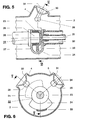
- FIG. 5 A constructively designed part of the switching device according to Figure 1 is shown in Figures 5 and 6.
- sections through the metal housing 2 of the switching device 1 in the region of the two flange attachments 4 and 5 are shown after the two outdoor bushings 7 and 8 have been removed.
- the section shown in Figure 5 is carried out along the axis of the tubular metal housing 2, whereas the section shown in Figure 6 is carried out essentially transversely to the axis.
- 21 denotes a shaft, which is made gas-tight from the metal housing 2 and consists of insulating material, of the drive 10 of the busbar disconnector 13 shown in FIGS. 1 and 2.
- the movable contact arrangement 22 is constructed from a bearing bush 23 and a circular sector-shaped section 24, which is attached to the bearing bush and extends radially outwards.
- the bearing bush 23 is rotatably supported on a cylindrical end section 25 of a fixed power connection 26 of the circuit breaker 12 arranged on the busbar side.
- a slide contact 27 serving for the current transmission from the busbar disconnector 13 to the circuit breaker 12 is arranged.
- the reference numerals 28 and 29 denote fixed contacts of the busbar disconnector 13, which are held by support insulators 30 and 31 in the region of the flange extensions 4 and 5.
- the support insulators 30 and 31 can be designed as partition insulators, which seal the inside of the metal housing 2 gas-tight to the outside. However, they are preferably designed as gas-permeable post insulators. Insulating gas from the interior of the metal housing then forms a total volume at the same pressure level with the interior of the gas-tight outdoor bushings 7 and 8.
- a support insulator 32 fastened on the end face of the metal housing 2 concentrically surrounds the shaft 21 and carries at its end facing away from the metal housing 2 a bracket-shaped holding part 33 which engages behind the movable contact arrangement 22 and on which the busbar-side power connection 26 of the circuit breaker 12 is supported.
- the power connection 26 of the circuit breaker 12 can also be supported on an insulator mounted on the inner lateral surface of the metal housing 2. The shaft 21 can then be guided into the interior of the housing via an opening provided on the outer surface of the metal housing 2.
- the movable contact arrangement of the busbar disconnector 13 can have four preferred positions:
- the section 24 contacts the fixed contact 28 and has thus connected the busbar SS1 to the power connection of the circuit breaker 12 on the busbar side. With the circuit breaker 12 closed, the busbar SS1 now feeds into the load outlet L.
- a second position (not shown in FIG. 6) can be achieved by rotating the shaft 21 clockwise.
- the section 24 shaped as a sufficiently large circular sector can additionally contact the fixed contact 29 without the galvanic connection between the busbar SS1 and the movable contact arrangement 22 being interrupted.
- the two busbars SS1 and SS2 are then connected to one another via the busbar disconnector 13.
- a third position can be reached (also not shown in FIG. 6).
- the fixed contact 28 and the movable contact arrangement 22 separate from one another and now only the fixed contact 29 and thus the busbar SS2 are connected to the busbar-side power connection 26 of the circuit breaker 12.
- the busbar SS2 is now connected to the load outlet L.
- the flange extension 5 can carry a metal cover 34 shown in dashed lines in FIG. 6, on the side of which is directed into the interior of the housing and is now attached to the fixed contact 29 of the busbar disconnector 13 which acts as a ground contact.
- the busbar disconnector 13 Then, in the second position, the busbar SS1 and at the same time the busbar-side power connection 26 of the circuit breaker 12 are grounded. In the third position, he only grounds the power connection 26 of the circuit breaker.
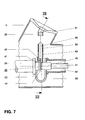
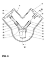
- FIGS. 7 and 8 show a busbar disconnector 13 which is modified compared to the busbar disconnector shown in FIGS. 5 and 6.
- the movable contact part 22 of this busbar disconnector does not have a rotatable, sector-shaped section 24 made of contact material, but a contact part 35 which is guided in a substantially displaceable manner in the direction of the axis of the tubular flange extension 4 and an essentially in Contact part 36, which is displaceably guided in the direction of the axis of the tubular flange shoulder 5.
- Each of the two contact parts 35 and 36 is guided in a metal sleeve 39, 40 which is at the potential of the busbar-side power connection 26 of the circuit breaker 12 and encloses at least one sliding contact 37 or 38.
- the two metal sleeves 39 and 40 are fastened to the busbar-side power connection 26 of the circuit breaker 12 by means of a metal connecting part 41 of L-shaped profile in such a way that they are at the same potential as the power connection 26 and that their sleeve axes are each on one of the two axes the flange approaches 4 and 5 are.
- a coupling rod 42, 43 of a gear 44 is articulated to the ends of the contact parts 35, 36 facing away from the fixed contacts 28, 29.
- the coupling rods 42 and 43 are articulated with their ends facing away from the contact parts 35 and 36, respectively, to a crank arm 45 of the transmission 44, which is rotated by the shaft 21 guided into the metal housing 2.
- the contact parts 35, 36 are inserted into the assigned fixed contacts 28, 29.
- the dimensions of the individual parts of the gear 44 as well as their articulation points and angular positions are selected such that when the shaft 21 is rotated, the one in the busbar disconnector 5 and 6 possible positions can be achieved.
- the first position shown in FIG. 8 in which only the busbar SS1 is connected to the busbar-side connection 26 of the circuit breaker 12, is first in the second position, in which both busbars are connected to one another, and then transferred to the third position, in which only the busbar SS2 is connected to the circuit breaker 12.
- a particular advantage of the design of the switching device 1 with the busbar disconnector according to FIGS. 7 and 8 is that by opening and closing the contacts in the axial direction, an arc that arises during switching is axially aligned and does not tend to migrate to the wall of the metal housing 2 .
- the switching device 1 according to the invention can advantageously be serviced and revised as follows:
Landscapes
- Engineering & Computer Science (AREA)
- Power Engineering (AREA)
- Gas-Insulated Switchgears (AREA)
Abstract
Die Schaltvorrichtung (1) weist ein geerdetes, isoliergasgefülltes Metallgehäuse (2) auf. Das Metallgehäuse (2) nimmt einen Leistungsschalter (12) und einen Erder (14) auf. Durch die Wand des Metallgehäuses (2) sind ein Stromanschluss für eine Sammelschiene (SS) und ein Stromanschluss für einen von einer Leitung (L) oder einem Kabel gebildeten Abgang geführt. Das Metallgehäuse (2) nimmt zusätzlich einen zwischen sammelschienenseitigen Stromanschluss und Leistungsschalter (12) geschalteten Sammelschienentrenner (13) auf und trägt eine Freiluftdurchführung (7) für den sammelschienenseitigen Stromanschluss.The switching device (1) has a grounded, insulating gas-filled metal housing (2). The metal housing (2) accommodates a circuit breaker (12) and an earth electrode (14). A power connection for a busbar (SS) and a power connection for an outlet formed by a line (L) or a cable are led through the wall of the metal housing (2). The metal housing (2) also accommodates a busbar disconnector (13) connected between the busbar-side power connection and the circuit breaker (12) and carries an outdoor bushing (7) for the busbar-side power connection.
Mit dieser Schaltvorrichtung (1) kann eine Vielzahl von Schaltungskonfigurationen zwischen der an Freiluft befindlichen Sammelschiene (SS) und dem Abgang realisiert werden. Zugleich sind die einzelnen Schalter (12, 13, 14, 17, 18) sowie platzsparend ausgebildete Sensoren (15, 16, 17, 18), etwa zur Stromund Spannungsmessung, dieser Schaltvorrichtung im schützenden und isolierenden Metallgehäuse (2) untergebracht. Gegenüber vergleichbar wirkenden Freiluftschaltvorrichtungen zeichnet sich die Schaltvorrichtung (1) daher durch eine kompaktere Bauweise und eine höhere Verfügbarkeit aus.
Description
Bei der Erfindung wird ausgegangen von einer Schaltvorrichtung nach dem Oberbegriff von Patentanspruch 1. Diese Schaltvorrichtung weist ein geerdetes, isoliergasgefülltes Metallgehäuse auf, welches einen Leistungs- und einen Erdungsschalter aufnimmt. Durch die Wand des Metallgehäuses sind mindestens ein Stromanschluss zu mindestens einer Sammelschiene und ein Stromanschluss zu einem Verbraucherabgang, etwa zu einer Leitung oder zu einem Kabel, geführt. Eine solche Schaltvorrichtung weist geringere Abmessungen auf als eine entsprechend wirkende Freiluft-Schaltvorrichtung, da durch die Isoliergasfüllung des Metallgehäuses die Durchschlagsfestigkeit gegenüber Luft vergrössert wird.The invention is based on a switching device according to the preamble of
Die Erfindung nimmt auf einen Stand der Technik von Schaltvorrichtungen Bezug wie er aus DE-PS 951 019 und DE 27 54 691 C2 bekannt ist.The invention relates to a prior art of switching devices as known from DE-PS 951 019 and DE 27 54 691 C2.
Die in DE-PS 951 019 beschriebene Schaltvorrichtung weist ein mit einem Isoliergas mit einer höheren Durchschlagsfestigkeit als Luft gefülltes Gehäuse auf, in dem Schalter, wie Leistungsschalter, Ausgangstrennschalter, Messwandler und Durchführungen enthalten sind. Ferner sind auch alle Vorrichtungen zur Betätigung der Schalter und alle Sicherungen und Überwachungseinrichtungen in dem Gehäuse untergebracht, so dass die Schaltvorrichtung eine betriebsfertige Schalteinheit darstellt, welche am Verwendungsort nur an die Sammelschienen und an die Steuerleitungen angeschlossen zu werden braucht. Die Sammelschienen und die zugehörigen Sammelschienentrenner sind in einem weiteren isoliergasgefüllten Gehäuse angeordnet. Zum Anschliessen der Schaltvorrichtung wird deshalb ein ebenfalls isoliergasgefüllter Verbindungskanal benötigt, welcher zwischen die Schaltvorrichtung und das Sammelschienengehäuse eingebaut wird.The switching device described in DE-PS 951 019 has a housing filled with an insulating gas with a higher dielectric strength than air, in which switches such as circuit breakers, output isolating switches, measuring transducers and bushings are contained. Furthermore, all devices for actuating the switches and all fuses and monitoring devices are accommodated in the housing, so that the switching device represents a ready-to-use switching unit which only needs to be connected to the busbars and the control lines at the place of use. The busbars and the associated ones Busbar isolators are arranged in a further housing filled with insulating gas. To connect the switching device, therefore, a connecting channel, which is also filled with insulating gas, is required, which is installed between the switching device and the busbar housing.
Die in DE 27 54 691 C1 beschriebene Schaltvorrichtung ist Teil einer metallgekapselten, druckgasisolierten Hochspannungsschaltanlage und weist einen mit SF6 von mehreren bar Druck gefüllten Druckbehälter auf, in dem ausser Leistungsschalter auch Stromwandler und Arbeitserder angeordnet sind und in dem durch feldspezifische stromführende Teile unterschiedliche Verknüpfungen dieser Geräte untereinander herstellbar sind. Der Druckbehälter ist mit zwei weiteren SF6-gefüllten Druckbehältern formschlüssig verbunden, von denen der eine alle anschlussseitig erforderlichen Geräte und stromführenden Teile, wie Trennschalter, Kabel- oder Freileitungs-Anschlusselemente und Erder, enthält und der andere alle zur Sammelschiene gehörenden Schaltgeräte und stromführenden Teile. Durch eine solche Schalteinrichtung wird in einer gasisolierten Hochspannungsschaltanlage, in der das Sammelschienenteil und das Abgangsteil jeweils in separaten Druckgasbehältern untergebracht sind, mit einer geringstmöglichen Anzahl von Druckbehältern eine hohe betriebstechnische Verfügbarkeit erreicht.The switching device described in
Ein in DE 33 18 344 A1 beschriebener Hochspannungsleistungsschalter weist eine in einem geerdeten, isoliergasgefüllten Metallgehäuse angeordnete Schalteinheit auf, deren beide Stromanschlüsse durch die Wand des Metallgehäuses an Freileitungen geführt sind. Im Zuge der Stromanschlüsse sind zwei Trennstellen angeordnet, welche nach Ablassen des Isoliergases und Öffnen des Metallgehäuses vom Montagepersonal betätigt werden können und dem Trennen und Verbinden der Stromanschlüsse bei der Demontage und der Montage der Schalteinheit dienen. Bei der Herstellung einer Schaltanlage werden dieser Schalter und alle weiteren Elemente der Schaltanlage komponentenweise montiert.A high-voltage circuit breaker described in
Der Erfindung, wie sie im Patentanspruch 1 angegeben ist, liegt die Aufgabe zugrunde, eine Schaltvorrichtung der eingangs genannten Art anzugeben, die sich durch eine kompaktere Bauweise und höhere Verfügbarkeit auszeichnet als eine vergleichbar wirkende Freiluftschaltvorrichtung und mit der zugleich eine Vielzahl von Schaltungskonfigurationen zwischen einer oder mehreren an Freiluft befindlichen Sammelschienen und einem Verbraucherabgang, etwa einem Kabel oder einer Freileitung, gebildet werden können.The invention, as specified in
Die Schaltvorrichtung nach der Erfindung zeichnet sich dadurch aus, dass der überwiegende Teil aller in einer Hochspannungsschaltanlage benötigten Schaltgeräte, wie Leistungsschalter, Sammelschienentrenner und Erder, in einem einzigen schottwandfreien Gasraum eines überwiegend rohrförmigen Metallgehäuses untergebracht sind. Eine solche Schaltvorrichtung kann als ganzes in sich geschlossenes Modul in der Fabrik vorgefertigt und geprüft werden. Vor Ort kann dann eine Hochspannungsschaltanlage durch Anschliessen eines über Freiluftdurchführung aus der Schaltvorrichtung geführten Stromanschlusses an die Sammelschiene(n) und eines weiteren aus der Schaltvorrichtung herausgeführten Stromanschlusses an ein Kabel oder eine Freileitung in äusserst rascher und einfacher Weise fertiggestellt werden. Von besonderem Vorteil ist es hierbei, dass die Schaltgeräte der Hochspannungsanlage nun nicht mehr dem direkten Einfluss des Wetters ausgesetzt sind und daher auch nach langen schaltfreien Zeiträumen eine hohe Verfügbarkeit aufweisen. Zugleich werden für alle wesentlichen Bestandteile der Anlage nun nicht mehr mehrere, den einzelnen Bestandteilen zugeordnete, Fundamente benötigt, sondern es reicht ein einziges, die Schaltvorrichtung tragendes, Fundament im allgemeinen aus.The switching device according to the invention is characterized in that the majority of all switching devices required in a high-voltage switchgear, such as circuit breakers, busbar disconnectors and earth electrodes, are accommodated in a single bulkhead-free gas space of a predominantly tubular metal housing. Such a switching device can be prefabricated and tested as a whole self-contained module in the factory. A high-voltage switchgear can then be completed on site in an extremely quick and simple manner by connecting a power connection led from the switching device to the busbar (s) and a further power connection led out of the switching device to a cable or an overhead line. It is particularly advantageous here that the switching devices of the high-voltage system are no longer exposed to the direct influence of the weather and are therefore highly available even after long, switch-free periods. At the same time, several foundations assigned to the individual components are no longer required for all the essential components of the system, but a single foundation supporting the switching device is generally sufficient.
Da die Schaltvorrichtung wegen des im Inneren ihres Metallgehäuses vorgesehenen Isoliergases geringe Isolationsabstände aufweist, ist sie klein und raumsparend ausgebildet und kann problemlos als Ersatz für mehrere in einem oder mehreren Abzweigen einer oder mehrerer Sammelschienen vorgesehene Schaltgeräte in irgendeine bereits existierende Freiluftschaltanlage eingebaut werden. Wegen der geringen räumlichen Abmessungen kann die Schaltvorrichtung nach der Erfindung problemlos in alle gängigen Schaltanlagen-Layouts eingebaut werden.Since the switching device has small insulation distances because of the insulating gas provided in the interior of its metal housing, it is small and space-saving and can easily be used as a replacement for several in one or more branches one or more busbars provided switchgear can be installed in any existing outdoor switchgear. Because of the small spatial dimensions, the switching device according to the invention can be easily installed in all common switchgear layouts.
Die Schaltvorrichtung nach der Erfindung eignet sich in besonders vorteilhafter Weise beim Retrofit bereits bestehender Freiluftschaltanlagen mit geringen Abmessungen. Durch den Einbau der Schaltvorrichtung nach der Erfindung können solche Anlagen besonders einfach und kostengünstig auf ein höheres Spannungsniveau ausgebaut werden.The switching device according to the invention is particularly advantageously suitable for retrofitting existing outdoor switchgear with small dimensions. By installing the switching device according to the invention, such systems can be expanded particularly easily and inexpensively to a higher voltage level.
Bei Bedarf können ohne weiteres zusätzliche Schaltgeräte, wie Abgangstrenner oder weitere Erder, und/oder Sensoren, wie insbesondere kapazitiv oder optisch wirkende Spannungssensoren und als Rogowski-Spule ausgebildete oder optisch wirkende Stromsensoren und/oder ein beide Sensoren kombinierender Strom- und Spannungssensor, in der Schaltvorrichtung vorgesehen sein. Da solche Sensoren im Gegensatz zu konventionellen Strom- und/oder Spannungswandlern äusserst platzsparend ausgebildet sind, kann die Schaltanlage nach der Erfindung ohne weiteres mit zusätzlichen Strom- und/oder Spannungssensoren nachgerüstet werden, welche dann beispielsweise die für synchronisierte und kontrollierte Einschaltvorgänge benötigte Spannungsmessung auf beiden Seiten des Schalters ermöglichen.If required, additional switching devices, such as outgoer isolators or further earth electrodes, and / or sensors, such as, in particular, capacitive or optically acting voltage sensors and Rogowski coil designed or optically acting current sensors and / or a current and voltage sensor combining both sensors, can be used in the Switching device may be provided. Since such sensors, in contrast to conventional current and / or voltage converters, are designed to be extremely space-saving, the switchgear according to the invention can easily be retrofitted with additional current and / or voltage sensors, which then, for example, the voltage measurement required for synchronized and controlled switch-on operations on both Allow sides of the switch.
Das Metallgehäuse weist zweckmässigerweise für jede Spannungsklasse ein Gehäuse definierter Abmessungen aus. Hierbei empfiehlt es sich, die Abmessungen so zu wählen, dass das Metallgehäuse neben Leistungsschalter, Sammelschienentrenner und Erder auch Abgangstrenner und Sensoren aufnehmen kann. Das Metallgehäuse kann dann je nach Bedarf alle diese Komponenten oder aber nur einen Teil dieser Komponenten enthalten. Dient die Schaltvorrichtung nach der Erfindung beispielsweise der Nachrüstung einer Freiluftschaltanlage, in der noch funktionsfähige Strom- und/oder Spannungswandler und Abgangstrenner vorhanden sind, so reicht es aus, wenn das Metallgehäuse Leistungsschalter, Sammelschienentrenner und Erder umfasst, und wenn beim Einbau in die Hochspannungsschaltanlage die noch vorhandenen Strom- und Spannungswandler an den Durchführungen angebracht und der noch vorhandene Abgangstrenner mit dem Abgang des Schaltvorrichtung verbunden wird.The metal housing expediently has a housing of defined dimensions for each voltage class. It is advisable to choose the dimensions so that the metal housing can accommodate circuit breakers, busbar disconnectors and earth electrodes as well as outgoer disconnectors and sensors. The metal housing can then contain all of these components or only a part of these components as required. If the switching device according to the invention is used, for example, to retrofit an outdoor switchgear assembly in which functional current and / or voltage converters and outgoing disconnectors are still present, so it is sufficient if the metal housing includes circuit breakers, busbar disconnectors and earth electrodes, and if the current and voltage transformers that are still present are attached to the bushings when the high-voltage switchgear is installed and the outgoing disconnector that is still present is connected to the switchgear outlet.
Bei entsprechender Ausbildung kann die Schaltvorrichtung sowohl in Anlagen mit Einfachsammelschiene als auch in Anlagen mit Doppelsammelschiene eingebaut werden. Eine besonders raumsparende Anordnung wird dann erreicht, wenn bei Einsatz der Schaltvorrichtung nach der Erfindung in einer Schaltanlage mit einer Doppelsammelschiene der Sammelschienentrenner als Mehrfach-Stellungstrenner ausgebildet ist und unterbrechungsfrei von der einen Sammelschiene auf die andere Sammelschiene schalten kann. Anstelle von zwei Freiluftdurchführungen, wie sie bei erfindungsgemässen Schaltvorrichtungem für Anlagen mit Doppelsammelschiene vorgesehen sind, kann bei Schaltvorrichtungen für Anlagen mit Einfachsammelschiene eine der beiden Freiluftdurchführungen entfernt und der am Metallgehäuse vorhandene und der Halterung der Freiluftdurchführung dienende Flanschansatz durch einen geerdeten Metalldeckel verschlossen werden, auf dessen ins Gehäuseinnere gerichteten Seite ein als Erdungskontakt wirkender, feststehender Kontakt des Sammelschienentrenners befestigt ist.With appropriate training, the switching device can be installed in systems with a single busbar as well as in systems with a double busbar. A particularly space-saving arrangement is achieved if, when using the switching device according to the invention in a switchgear assembly with a double busbar, the busbar isolator is designed as a multiple position isolator and can switch from one busbar to the other busbar without interruption. Instead of two outdoor feedthroughs, as are provided in switching devices according to the invention for systems with double busbars, in switching devices for systems with single busbars, one of the two outdoor feedthroughs can be removed and the flange attachment on the metal housing and used to hold the outdoor feedthrough can be closed by an earthed metal cover a fixed contact of the busbar disconnector, which acts as a grounding contact, is attached to the inside of the housing.
Bei entsprechender Gestaltung kann die Schaltvorrichtung nach der Erfindung sowohl einphasig als auch mehrphasig gekapselt ausgebildet sein.With a corresponding design, the switching device according to the invention can be encapsulated both single-phase and multi-phase.
Bevorzugte Ausführungsbeispiele der Erfindung und die damit erzielbaren weiteren Vorteile werden nachfolgend anhand von Zeichnungen näher erläutert. Hierbei zeigt:
- Fig.1
- eine Seitenansicht einer ersten Ausführungsform der Schaltvorrichtung nach der Erfindung mit einem im wesentlichen rohrförmigen Gehäuse,
- Fig.2
- eine Ansicht der Schaltvorrichtung nach Fig.1 von rechts in Richtung der Rohrachse,
- Fig.3
- ein Prinzipschaltbild der Schaltvorrichtung nach Fig.1,
- Fig.4
- ein Prinzipschaltbild einer zweiten Ausführungsform der Schaltvorrichtung nach der Erfindung,
- Fig.5
- eine Aufsicht auf einen längs der Rohrachse geführten Schnitt durch einen Abschnitt der Schaltvorrichtung nach Fig.1,
- Fig.6
- eine Aufsicht auf einen längs VI-VI geführten Schnitt durch die Schaltvorrichtung nach Fig.5,
- Fig.7
- eine Aufsicht auf einen längs der Rohrachse geführten Schnitt durch einen Abschnitt einer abgewandelten Ausführungsform der Schaltvorrichtung nach Fig.1, und
- Fig.8
- eine Aufsicht auf einen längs VIII-VIII geführten Schnitt durch die Schaltvorrichtung nach Fig.7.
- Fig. 1
- 2 shows a side view of a first embodiment of the switching device according to the invention with an essentially tubular housing,
- Fig. 2
- 1 from the right in the direction of the tube axis,
- Fig. 3
- 2 shows a basic circuit diagram of the switching device according to FIG. 1,
- Fig. 4
- 2 shows a basic circuit diagram of a second embodiment of the switching device according to the invention,
- Fig. 5
- 1 shows a plan view of a section along the tube axis through a section of the switching device according to FIG. 1,
- Fig. 6
- 4 shows a top view of a section taken along VI-VI through the switching device according to FIG. 5,
- Fig. 7
- a plan view of a section along the tube axis through a section of a modified embodiment of the switching device according to Figure 1, and
- Fig. 8
- a top view of a section taken along VIII-VIII through the switching device according to Figure 7.
In allen Figuren bezeichnen gleiche Bezugszeichen gleichwirkende Teile. Die in den Figuren 1 und 2 dargestellte und mit dem Bezugszeichen 1 gekennzeichnete Schaltvorrichtung weist ein mit Isoliergas, wie etwa SF6 von einigen bar Druck, gefülltes, im wesentlichen rohrförmig ausgebildetes Metallgehäuse 2 auf. Das Metallgehäuse 2 ist auf einem nicht bezeichneten Gestell gelagert und befindet sich auf Erdpotential. Das Metallgehäuse weist an seiner Mantelfäche drei nicht ersichtliche Öffnungen auf, welche jeweils von einem von drei rohrförmige Flanschansätzen 3, 4 und 5 begrenzt sind. An den vom Metallgehäuse 2 abgewandten Enden der Flanschansätze ist jeweils eine von drei Freiluftdurchführungen 6, 7 und 8 gehalten. Diese Freiluftdurchführungen weisen bevorzugt jeweils ein faserverstärktes Kunststoffgehäuse mit einer Silikonbeschirmung auf. Hierdurch wird die Schaltvorrichtung gegenüber einer mit Porzellanisolatoren ausgerüsteten Vorrichtung nicht nur erheblich leichter und daher besser transportfähig, sondern ist zugleich auch das Risiko einer Explosion der Durchführungen, etwa infolge von Montage- oder Wartungsarbeiten in der Anlage oder beim Einwirken von Umbruchkräften, praktisch gebannt. Die Achsen der Flanschansätze 3, 4 und 5 stehen typischerweise in einem Winkel von ca. 50° auf der Rohrachse des Metallgehäuses 2. Die Flanschansätze 4 und 5 sind gegeneinander um einen Winkel von typischerweise 80 bis 100° geneigt. Durch die gewinkelte Anordnung der Flanschansätze kann die erforderliche dielektrische Festigkeit an Luft mit einer möglichst kleinen Gehäuseabmessung realisiert werden.In all figures, the same reference numerals designate parts with the same effect. The switching device shown in FIGS. 1 and 2 and identified by the
Das Metallgehäuse 2 weist an seinen beiden Stirnseiten zwei weitere, ebenfalls nicht ersichtliche Öffnungen auf. Durch die eine Öffnung ist ein Antrieb 9 für einen im Inneren des Metallgehäuses befindlichen Leistungsschalter und durch die andere Öffnung ein Antrieb 10 für einen ebenfalls im Gehäuseinneren befindlichen Sammelschienentrenner jeweils in gasdichter Weise geführt. Auf seiner Mantelfläche weist das Metallgehäuses 2 eine weitere nicht ersichtliche Öffnung auf, durch die in gasdichter Weise ein Antrieb 11 für einen im Metallgehäuse 2 befindlichen Erder geführt ist.The
Aus Fig.3 ist zu erkennen, dass das Metallgehäuse 2 der Schaltvorrichtung einen Leistungsschalter 12 aufnimmt, dessen einer Stromanschluss über einen als Mehrfach-Stellungstrenner ausgeführten Sammelschienentrenner 13 und eine der beiden Freiluftdurchführungen 7 oder 8 mit einer Sammelschiene SS1 oder SS2 einer Hochspannungsschaltanlage und dessen anderer Stromanschluss über die Freiluftdurchführung 6 mit einem Verbraucherabgang, etwa einem Kabel oder einer Leitung L der Hochspannungsschaltanlage, verbunden ist. Das Metallgehäuse 3 nimmt ferner einen zwischen dem abgangsseitigen Stromanschluss des Leistungsschalters 12 und dem geerdeten Metallgehäuse 2 geschalteten Erder 14 auf sowie Sensoren, wie einen Stromsensor 15 und einen Spannungssensor 16, welche am verbraucherseitigen Stromanschluss des Leistungsschalters 12 den Strom und die Spannung detektieren. Die Sensoren 15, 16 sind platzsparend ausgebildet. Der Stromsensor 15 kann als Rogowskispule oder optischer Sensor, der Spannungssensor 16 als kapazitiver Spannungsteiler oder optischer Sensor ausgeführt sein. Alternativ können die beiden Sensoren in einem einzigen Sensor kombiniert sein.It can be seen from FIG. 3 that the
Wie in Fig.4 dargestellt ist, kann alternativ die Freiluftdurchführung 8 entfallen und der Leistungsschalter 12 über einen als 2-Stellungstrenner ausgeführten Sammelschienentrenner 13 und die Freiluftdurchführung 7 mit lediglich einer Sammelschiene SS der Hochspannungsschaltanlage verbunden sein. Zusätzlich können auch ein zwischen den sammelschienenseitigen Stromanschluss des Leistungsschalters 12 und das geerdete Metallgehäuse 2 geschalteter Erder 17 und/oder ein zwischen den abgangsseitigen Stromanschluss des Leistungsschalters und den Stromleiter der Freiluftdurchführung 6 geschalteter Abgangstrenner 18 und/oder ein weiterer Spannungssensor 19 und ein weiterer Stromsensor 20 vorgesehen sein. Die Sensoren 19, 20 detektieren am sammelschienenseitigen Stromanschluss des Leistungsschalters 12 Strom und Spannung. Zusammen mit den Sensoren 15, 16 können so Differenzströme und/oder -spannungen über dem Leistungsschalter 12 ermittelt werden, wodurch ein gegebenenfalls erwünschtes synchrones Schalten des Leistungsschalters ermöglicht wird.As shown in FIG. 4, the
Durch das Unterbringen von Spannungs- und Stromsensoren und weiterer Sensoren, etwa zur Messung von Druck, Dichte oder Temperatur oder von Teilentladungen, in einem einzigen Gehäuse werden Gehäusedurchführungen eingespart und können zugleich die zur Übertragung der von den Sensoren ermittelten Informationen benötigten Wege kurz gehalten werden. Darüber hinaus sind durch die kompakte Bauweise auch sämtliche zur Steuerung und Regelung der Schaltgeräte der Schaltvorrichtung 1 benötigten Verbindungen für den Austausch von Information zwischen den Sensoren und den Schaltgeräten kurz und zentral an einem Ort untergebracht. Zur Erfüllung ihrer leittechnische Funktionsfähigkeit ist es daher nurmehr notwendig, die Schaltvorrichtung 1 in einfacher Weise über einen einzigen Bus mit einem leittechnische Aufgaben erfüllenden Steuerschrank zu verbinden.Housing voltage and current sensors and other sensors, for example for measuring pressure, density or temperature or partial discharges, in a single housing saves housing bushings and at the same time the distances required to transmit the information determined by the sensors can be kept short. In addition, are through the compact design also accommodates all the connections required for the control and regulation of the switching devices of the
Ein konstruktiv ausgeführter Teil der Schaltvorrichtung nach Fig.1 ist in den Figuren 5 und 6 angegeben. In diesen Figuren sind Schnitte durch das Metallgehäuse 2 der Schaltvorrichtung 1 im Bereich der beiden Flanschansätze 4 und 5 nach Entfernen der beiden Freiluftdurchführungen 7 und 8 dargestellt. Der in Fig.5 dargestellte Schnitt ist längs der Achse des rohrförmigen Metallgehäuse 2 ausgeführt, wohingegen der in Fig.6 dargestellte Schnitt im wesentlichen quer zur Achse ausgeführt ist.A constructively designed part of the switching device according to Figure 1 is shown in Figures 5 and 6. In these figures, sections through the
In den beiden Figuren 5 und 6 bezeichnet 21 eine gasdicht aus dem Metallgehäuse 2 geführte, aus Isoliermaterial bestehende Welle des aus den Figuren 1 und 2 ersichtlichen Antriebs 10 des Sammelschienentrenners 13. An dem ins Metallgehäuse 2 geführten Ende der Welle 21 ist eine bewegliche Kontaktanordnung 22 des Sammelschienentrenners 13 befestigt. Die bewegliche Kontaktanordnung 22 ist aus einer Lagerbuchse 23 und einem an der Lagerbuchse angesetzten und sich radial nach aussen erstreckenden, kreissektorförmigen Abschnitt 24 Kontaktmaterial aufgebaut. Die Lagerbuchse 23 ist drehbar auf einem zylinderförmig ausgebildeten Endabschnitt 25 eines sammelschienenseitig angeordneten, feststehenden Stromanschlusses 26 des Leistungsschalters 12 abgestützt. Zwischen der Mantelfläche des Endabschnitts 25 und der Innenfläche der Lagerbuchse 23 ist ein der Stromübertragung vom Sammelschienentrenner 13 auf den Leistungsschalter 12 dienender Gleitkontakt 27 angeordnet. Die Bezugszeichen 28 und 29 bezeichnen feststehende Kontakte des Sammelschienentrenners 13, welche von Stützisolatoren 30 und 31 im Bereich der Flanschansätze 4 und 5 gehalten sind. Bei der Montage der Freiluftdurchführungen 7 und 8 werden diese Kontakte mit dem Stromleiter der Freiluftdurchführungen verbunden und dienen dann dem Stromanschluss der Schaltvorrichtung 1 an die Sammelschienen SS1 und SS2. Die Stützisolatoren 30 und 31 können als Schottungsisolatoren ausgebildet sein, die das Innere des Metallgehäuses 2 gasdicht nach aussen hin abschliessen. Sie sind jedoch vorzugsweise als gasdurchlässige Stützisolatoren ausgebildet. Isoliergas aus dem Inneren des Metallgehäuses bildet dann mit dem Inneren der gasdicht ausgeführten Freiluftdurchführungen 7 und 8 ein auf gleichem Druckniveau befindliches Gesamtvolumen.In the two FIGS. 5 and 6, 21 denotes a shaft, which is made gas-tight from the
Ein auf der Stirnseite des Metallgehäuses 2 befestigter Stützisolator 32 umgibt die Welle 21 konzentrisch und trägt an seinem vom Metallgehäuse 2 abgewandten Ende ein die bewegliche Kontaktanordnung 22 hintergreifendes bügelförmiges Halteteil 33, auf dem der sammelschienenseitige Stromanschluss 26 des Leistungsschalters 12 abgestützt ist. Alternativ kann der Stromanschluss 26 des Leistungsschalters 12 auch auf einem auf der inneren Mantelfläche des Metallgehäuses 2 gelagerten Isolator abgestützt sein. Die Welle 21 kann dann über eine an der Mantelfläche des Metallgehäuses 2 vorgesehenen Öffnung ins Gehäuseinnere geführt sein.A
Die bewegliche Kontaktanordnung des Sammelschienentrenners 13 kann vier bevorzugte Stellungen einnehmen:The movable contact arrangement of the
In einer ersten Stellung (in Fig.6 gestrichelt dargestellt) kontaktiert der Abschnitt 24 den feststehenden Kontakt 28 und hat so die Sammelschiene SS1 mit dem sammelschienenseitigen Stromanschluss des Leistungsschalter 12 verbunden. Bei geschlossenem Leistungsschalter 12 speist nun die Sammelschiene SS1 in den Verbraucherabgang L ein.In a first position (shown in dashed lines in FIG. 6), the
Bei geöffnetem Leistungsschalter 12 kann durch Drehen der Welle 21 im Uhrzeigersinn eine zweite Stellung (in Fig.6 nicht dargestellt) erzielt werden. Der als ausreichend grosser Kreissektor geformte Abschnitt 24 kann den feststehenden Kontakt 29 zusätzlich kontaktieren, ohne dass die galvanische Verbindung zwischen der Sammelschiene SS1 und der beweglichen Kontaktanordnung 22 unterbrochen wird. Es sind dann die beiden Sammelschiene SS1 und SS2 über den Sammelschienentrenner 13 miteinander verbunden.With the
Durch Weiterdrehen der Welle 21 im Uhrzeigersinn kann bei geöffnetem Leistungsschalter 12 eine dritte Stellung erreicht werden (in Fig.6 ebenfalls nicht dargestellt). Beim Übergang von der zweiten in die dritte Stellung trennen sich der feststehende Kontakt 28 und die bewegliche Kontaktanordnung 22 voneinander und sind nun nur noch der feststehende Kontakt 29 und damit die Sammelschiene SS2 mit dem sammelschienenseitigen Stromanschluss 26 des Leistungsschalters 12 verbunden. Bei geschlossenem Leistungsschalter 12 ist nun die Sammelschiene SS2 mit dem Verbraucherabgang L verbunden.By rotating the
Durch Weiterdrehen der Welle 21 bei geöffnetem Leistungsschalter 12 im Uhrzeigersinn wird die in Fig.6 durchgezogen dargestellte vierte Stellung erreicht, in der nun auch die beiden Kontakte 29 und 22 voneinander getrennt sind. Der kreissektorförmige Abschnitt 24 der bewegliche Kontaktanordnung 22 ist nun in das bügelförmige Halteteil 33 eingefahren und kontaktiert dann weder den feststehenden Kontakt 28 noch den feststehenden Kontakt 29. In dieser Stellung können möglicherweise im Leistungsschalter 12 bzw. in Steuerkondensatoren des Leistungsschalters 12 vorhandene elektrische Ladungen durch Erdung entfernt werden (z.B. durch einen entsprechend dem Erder 17 gemäss Fig.4 angeordneten Erder).By rotating the
Anstelle der Freiluftdurchführung 8 kann der Flanschansatz 5 einen in Fig.6 gestrichelt dargestellten Metalldeckel 34 tragen, auf dessen ins Gehäuseinnere gerichteten Seite der nun als Erdungskontakt wirkende, feststehende Kontakt 29 des Sammelschienentrenners 13 befestigt ist. Der Sammelschienentrenner 13 erdet dann in der zweiten Stellung die Sammelschiene SS1 und gleichzeitig den sammelschienenseitigen Stromanschluss 26 des Leistungsschalters 12. In der dritten Stellung erdet er nur noch den Stromanschluss 26 des Leistungsschalters.Instead of the
In den Figuren 7 und 8 ist ein gegenüber dem in den Figuren 5 und 6 dargestellten Sammelschienentrenner abgeänderter Sammelschienentrenner 13 dargestellt. Im Unterschied zum Sammelschienentrenner 13 nach den Figuren 5 und 6 weist das bewegliche Kontaktteil 22 dieses Sammelschienentrenners nicht einen drehbaren, kreissektorförmigen Abschnitt 24 aus Kontaktmaterial auf, sondern ein im wesentlichen in Richtung der Achse des rohrförmigen Flanschansatzes 4 verschieblich geführtes Kontaktteil 35 sowie ein im wesentlichen in Richtung der Achse des rohrförmigen Flanschansatzes 5 verschieblich geführtes Kontaktteil 36. Jedes der beiden Kontaktteile 35 bzw. 36 ist in einer auf dem Potential des sammelschienenseitigen Stromanschlusses 26 des Leistungsschalters 12 befindlichen und mindestens einen Gleitkontakt 37 bzw. 38 umschliessenden Metallhülse 39, 40 geführt. Die beiden Metallhülsen 39 und 40 sind mittels eines metallenen Verbindungsteils 41 von L-förmigem Profil derart am sammelschienenseitigen Stromanschluss 26 des Leistungsschalters 12 befestigt, dass sie sich auf dem gleichen Potential wie der Stromanschluss 26 befinden, und dass ihre Hülsenachsen jeweils auf einer der beiden Achsen der Flanschansätze 4 und 5 liegen. An die von den feststehenden Kontakten 28, 29 abgewandten Enden der Kontaktteile 35, 36 ist jeweils eine Koppelstange 42, 43 eines Getriebes 44 angelenkt. Die Koppelstangen 42 und 43 sind mit ihren von den Kontaktteilen 35 bzw. 36 abgewandten Enden an einen Kurbelarm 45 des Getriebes 44 angelenkt, welcher von der ins Metallgehäuse 2 geführten Welle 21 gedreht wird.FIGS. 7 and 8 show a
Je nach Stellung des Sammelschienentrenners sind die Kontaktteile 35, 36 in die zugeordneten feststehenden Kontakte 28, 29 eingefahren. Die Abmessungen der einzelnen Teile des Getriebes 44 sowie deren Anlenkstellen und Winkelpositionen sind so gewählt, dass beim Drehen der Welle 21 die beim Sammelschienentrenner nach den Figuren 5 und 6 möglichen Stellungen erreicht werden. So wird durch Drehen der Welle 21 im Uhrzeigersinn die aus Fig.8 ersichtliche erste Stellung, in der lediglich die Sammelschiene SS1 mit dem sammelschienenseitigen Anschluss 26 des Leistungsschalters 12 verbunden ist, zunächst in die zweite Stellung, in der beide Sammelschienen miteinander verbunden sind, und danach in die dritte Stellung überführt, in der lediglich die Sammelschiene SS2 mit dem Leistungsschalter 12 verbunden ist.Depending on the position of the busbar disconnector, the
Ein besonderer Vorteil der Ausbildung der Schaltvorrichtung 1 mit dem Sammelschienentrenner gemäss den Figuren 7 und 8 besteht darin, dass durch das Öffnen und Schliessen der Kontakte in axialer Richtung ein beim Schalten entstehender Lichtbogen axial ausgerichtet ist und nicht zum Auswandern auf die Wand des Metallgehäuses 2 neigt.A particular advantage of the design of the
Die Schaltvorrichtung 1 nach der Erfindung lässt sich mit Vorteil wie folgt warten und revidieren:The
Ist die Schaltvorrichtung für den Einsatz in einer Hochspannungsschaltanlage mit einer einfachen Sammelschiene SS (Schaltvorrichtung gemäss Fig.4) vorgesehen, so sind folgende Verfahrensschritte auszuführen:
- (1) Öffnen des Leistungsschalter 12
- (2) Freischalten des Verbraucherabgangs (Kabel oder Leitung L) durch Öffnen des Abgangstrenners 18 sowie des Trenners der Gegenstation
- (3) Öffnen des Sammelschienentrenners 13
- (4) Freischalten der Sammelschiene SS in der Anlage
- (5)
Betätigung der Erder 14 und 17 - (6) Manuelles Erden der freigeschalteten Sammelschiene SS und des freigeschalteten Verbraucherabgangs mittels Erdungsstangen
- (7) Kurzschliessen der durch
das Metallgehäuse 2 geführten Stromanschlüsse - (8) Lösen der Anschlussverbindungen zur Sammelschiene SS und zum Verbraucherabgang
- (9)
Ausfahren der Schaltvorrichtung 1.
- (1) Opening the
circuit breaker 12 - (2) Activation of the consumer outlet (cable or line L) by opening the
outlet isolator 18 and the isolator of the opposite station - (3) Open the
busbar disconnector 13 - (4) Disconnect the SS busbar in the system
- (5) Operation of the
earth electrodes - (6) Manual earthing of the released busbar SS and the released consumer outlet using earthing rods
- (7) Short circuit the power connections through the
metal housing 2 - (8) Loosen the connection connections to the busbar SS and to the consumer outlet
- (9) Extending the
switching device 1.
Ist die Schaltvorrichtung für den Einsatz in einer Hochspannungsschaltanlage mit einer Doppelsammelschiene SS1 und SS2 (Schaltvorrichtung gemäss Fig.3) vorgesehen, so sind folgende Verfahrensschritte auszuführen:
- (1) Öffnen des Leistungsschalter 12
- (2) Freischalten des Verbraucherabgangs (Kabel oder Leitung L) durch Öffnen eines innerhalb oder ausserhalb des Metallgehäuses 2 vorgesehenen Abgangstrenners sowie des Trenners der Gegenstation
- (3) Öffnen des Sammelschienentrenners 13 durch Führen des Abschnitts 24 in die vierte (neutrale) Stellung
- (4) Freischalten der Sammelschiene SS1
- (5) Betätigung des Erders 14 und eines gegebenenfalls zusätzlich vorgesehenen Erders 17
- (6) Manuelles Erden der freigeschalteten Sammelschiene SS1 und des freigeschalteten Verbraucherabgangs mittels Erdungsstangen
- (7) Kurzschliessen der durch
das Metallgehäuse 2 geführten Stromanschlüsse zur Sammelschiene SS1 und zum Verbraucherabgang - (8) Lösen der Anschlussverbindungen zur Sammelschiene SS1 und zum Verbraucherabgang
- (9) Aufheben der Erdung der Sammelschiene SS1, wodurch diese Sammelschiene wieder in Betrieb genommen werden kann und alle Verbraucher von der Sammelschiene SS2 auf die Sammelschiene SS1 geschaltet werden können
- (10) Freischalten der Sammelschiene SS2
- (11) Manuelles Erden der Sammelschiene SS2 mittels einer Erdungsstange
- (12) Kurzschliessen des durch
das Metallgehäuse 2 geführten Stromanschlusses zur Sammelschiene SS2 - (13) Lösen der Anschlussverbindung zur Sammelschiene SS2
- (14)
Ausfahren der Schalteinrichtung 1.
- (1) Opening the
circuit breaker 12 - (2) Enabling the consumer outlet (cable or line L) by opening an outlet isolator provided inside or outside the
metal housing 2 and the isolator of the opposite station - (3) Open the
busbar disconnector 13 by guiding thesection 24 to the fourth (neutral) position - (4) Disconnect the SS1 busbar
- (5) Actuation of the
earth 14 and anearth 17, which may be additionally provided - (6) Manual earthing of the released busbar SS1 and the released consumer outlet using earthing rods
- (7) Short-circuit the power connections through the
metal housing 2 to the busbar SS1 and to the consumer outlet - (8) Disconnect the connections to the SS1 busbar and the consumer outlet
- (9) Removing the earthing of the busbar SS1, whereby this busbar can be put back into operation and all consumers can be switched from the busbar SS2 to the busbar SS1
- (10) Disconnect the SS2 busbar
- (11) Manually ground the SS2 busbar using an earth rod
- (12) Short circuit the power connection through the
metal housing 2 to the busbar SS2 - (13) Disconnect the connection to the SS2 busbar
- (14) Extending the
switching device 1.
- 11
- SchaltvorrichtungSwitching device
- 22nd
- MetallgehäuseMetal case
- 3, 4, 53, 4, 5
- FlanschansätzeFlange approaches
- 6, 7, 86, 7, 8
- FreiluftdurchführungenOutdoor bushings
- 9, 10, 119, 10, 11
- AntriebeDrives
- 1212th
- LeistungsschalterCircuit breaker
- 1313
- SammelschienentrennerBusbar disconnector
- 1414
- ErderEarth
- 1515
- StromsensorCurrent sensor
- 1616
- SpannungssensorVoltage sensor
- 1717th
- ErderEarth
- 1818th
- AbgangstrennerOutlet isolator
- 1919th
- SpannungssensorVoltage sensor
- 2020th
- StromsensorCurrent sensor
- 2121
- Wellewave
- 2222
- beweglicher Kontaktmoving contact
- 2323
- LagerbuchseBearing bush
- 2424th
- Abschnittsection
- 2525th
- EndabschnittEnd section
- 2626
- StromanschlussPower connection
- 2727
- GleitkontaktSliding contact
- 28, 2928, 29
- Kontaktecontacts
- 30, 31, 3230, 31, 32
- StützisolatorenPost insulators
- 3333
- HalteteilHolding part
- 3434
- MetalldeckelMetal lid
- 35, 3635, 36
- KontaktteileContact parts
- 37, 3837, 38
- GleitkontakteSliding contacts
- 39, 4039, 40
- MetallhülsenMetal sleeves
- 4141
- VerbindungsteilConnecting part
- 42, 4342, 43
- KoppelstangenCoupling rods
- 4444
- Getriebetransmission
- 4545
- KurbelarmCrank arm
- SS, SS1, SS2SS, SS1, SS2
- SammelschienenBusbars
- LL
- Leitungmanagement
Claims (22)
Applications Claiming Priority (2)
| Application Number | Priority Date | Filing Date | Title |
|---|---|---|---|
| DE19511168A DE19511168A1 (en) | 1995-03-28 | 1995-03-28 | Switching device |
| DE19511168 | 1995-03-28 |
Publications (3)
| Publication Number | Publication Date |
|---|---|
| EP0735637A2 true EP0735637A2 (en) | 1996-10-02 |
| EP0735637A3 EP0735637A3 (en) | 1996-12-27 |
| EP0735637B1 EP0735637B1 (en) | 2002-12-11 |
Family
ID=7757857
Family Applications (1)
| Application Number | Title | Priority Date | Filing Date |
|---|---|---|---|
| EP96810139A Expired - Lifetime EP0735637B1 (en) | 1995-03-28 | 1996-03-07 | Switchgear having a grounded metal casing filled with insulating gas |
Country Status (7)
| Country | Link |
|---|---|
| US (1) | US5796060A (en) |
| EP (1) | EP0735637B1 (en) |
| JP (1) | JPH08275323A (en) |
| CN (1) | CN1061181C (en) |
| CA (1) | CA2168637A1 (en) |
| DE (2) | DE19511168A1 (en) |
| RU (1) | RU2196376C2 (en) |
Cited By (11)
| Publication number | Priority date | Publication date | Assignee | Title |
|---|---|---|---|---|
| EP0878816A3 (en) * | 1997-05-14 | 1999-08-11 | ABBPATENT GmbH | Metal-clad gas insulated power switch |
| FR2937175A1 (en) * | 2008-10-14 | 2010-04-16 | Areva T & D Sa | ELECTRICAL SWITCHING APPARATUS HAVING TWO SWITCHES, SUCH AS A BAR BREAKER AND A GROUND DISCONNECT AND COMPRISING COMMON TRAINING MEANS OF THE MOBILE SWITCH CONTACTS. |
| FR2937177A1 (en) * | 2008-10-14 | 2010-04-16 | Areva T & D Ag | ELECTRICAL SWITCHING APPARATUS HAVING TWO SWITCHES, SUCH AS A BAR DISCONNECT AND A GROUND DISCONNECT AND COMPRISING TRAINING MEANS COMMON TO THE MOBILE SWITCH CONTACTS. |
| RU2406199C1 (en) * | 2009-06-30 | 2010-12-10 | Закрытое акционерное общество "ЧЕБОКСАРСКИЙ ЭЛЕКТРОМЕХАНИЧЕСКИЙ ЗАВОД" | DEVICE FOR SECTIONING AIR AND CABLE LINES FOR 35 kV POWER SUPPLY SYSTEMS |
| WO2010149486A1 (en) | 2009-06-23 | 2010-12-29 | Siemens Aktiengesellschaft | High-voltage arrangement |
| WO2010149482A3 (en) * | 2009-06-23 | 2011-03-03 | Siemens Aktiengesellschaft | Mechanical actuating device for three-position disconnector |
| US8080746B2 (en) | 2005-11-02 | 2011-12-20 | Abb Technology Ag | High-voltage circuit breaker and switch arrangement |
| CN102339684A (en) * | 2010-07-16 | 2012-02-01 | 日本Ae帕瓦株式会社 | Disconnecting switch with earthing switch |
| US8173927B2 (en) | 2008-10-14 | 2012-05-08 | Areva T&D Ag | High and medium voltage switch apparatus with two interrupters, having common means for actuating the movable contacts of the interrupters |
| WO2017141060A1 (en) | 2016-02-18 | 2017-08-24 | Koncar - Elektricni Visokonaponski Aparati D.D. | Combined disconnecting-earthing switching module for a gas-insulated switchgear |
| RU178773U1 (en) * | 2017-10-31 | 2018-04-19 | Закрытое акционерное общество "Группа компаний "Электрощит"-ТМ Самара" | SWITCH SIGNAL CONTROL ASSEMBLY FOR MAIN KNIVES OF DISCONNECTOR AND EARTH |
Families Citing this family (65)
| Publication number | Priority date | Publication date | Assignee | Title |
|---|---|---|---|---|
| DE19608285A1 (en) * | 1996-02-23 | 1997-08-28 | Siemens Ag | High voltage outdoor switch |
| DE19641391C1 (en) * | 1996-09-27 | 1998-02-19 | Siemens Ag | Hybrid type high-voltage switchgear |
| DE19649613A1 (en) * | 1996-11-29 | 1998-06-04 | Abb Patent Gmbh | Circuit-breaker module for gas-insulated high voltage (HV) switchgear |
| DE29700930U1 (en) * | 1997-01-09 | 1997-04-03 | Siemens AG, 80333 München | High-voltage switchgear with a dead tank switch |
| FR2759818B1 (en) * | 1997-02-20 | 1999-04-02 | Gec Alsthom T & D Sa | SWITCHING SYSTEM INCLUDING A CURRENT INJECTION SWITCH INTEGRATED WITH A GENERATOR BREAKER |
| NL1007499C2 (en) * | 1997-11-10 | 1999-05-11 | Elin Holec High Voltage Bv | Switching device for medium voltage. |
| FR2771560B1 (en) * | 1997-11-24 | 2000-01-28 | Gec Alsthom T & D Sa | SWITCHING DEVICE FOR A POWER PLANT GENERATOR AND A TRANSFORMER WITH A THREE-POSITION DISCONNECTOR CONNECTED TO THE TRANSFORMER |
| FR2771561B1 (en) * | 1997-11-24 | 2000-01-28 | Gec Alsthom T & D Sa | SWITCHING DEVICE FOR A POWER PLANT GENERATOR AND A TRANSFORMER WITH A THREE-POSITION DISCONNECTOR |
| DE19825386C2 (en) * | 1998-05-28 | 2000-05-11 | Siemens Ag | Encapsulation module with a combined isolating-earthing switch for a gas-insulated switchgear |
| DE19838251B4 (en) * | 1998-08-22 | 2007-01-18 | Abb Schweiz Ag | Gas-insulated switchgear with fastening means |
| IT1302715B1 (en) * | 1998-10-20 | 2000-09-29 | Abb Ricerca Spa | INTERRUPT AND SECTIONING EQUIPMENT ISOLATED IN GAS |
| DE29823222U1 (en) * | 1998-12-23 | 1999-02-25 | Siemens AG, 80333 München | Gas-insulated, three-phase encapsulated switchgear |
| DE19907887A1 (en) * | 1999-02-24 | 2000-08-31 | Asea Brown Boveri | Control disc for gearbox of a disconnector and a method for producing such a control disc |
| IT1311070B1 (en) * | 1999-03-04 | 2002-02-28 | Abb Ricerca Spa | SUBSTATION FOR THE TRANSMISSION AND DISTRIBUTION OF ELECTRICITY FOR HIGH AND / OR MEDIUM VOLTAGE APPLICATIONS. |
| ITMI991177A1 (en) * | 1999-05-27 | 2000-11-27 | Abb Ricerca Spa | SUBSTATION FOR THE TRANSMISSION AND DISTRIBUTION OF ELECTRICITY FOR HIGH AND / OR MEDIUM VOLTAGE APPLICATION |
| US6137068A (en) * | 1999-06-01 | 2000-10-24 | Astec International Limited | Combined handle-guard and grip for plug-in circuit breakers |
| US6560123B1 (en) | 1999-06-04 | 2003-05-06 | Astec International Limited | Plug-in GMT fuse block |
| US6315580B1 (en) | 1999-06-04 | 2001-11-13 | Astec International Limited | PCB connector module for plug-in circuit breakers and fuses |
| US6530811B1 (en) | 1999-06-04 | 2003-03-11 | Astec International Limited | Modular distribution assembly |
| DE29912028U1 (en) | 1999-07-02 | 1999-09-23 | Siemens AG, 80333 München | High voltage circuit breakers |
| IT1313732B1 (en) * | 1999-09-15 | 2002-09-17 | Abb Ricerca Spa | INTERRUPT AND SECTIONING EQUIPMENT INSULATED IN GAS |
| IT1313744B1 (en) * | 1999-09-17 | 2002-09-17 | Abb Ricerca Spa | INTERRUPTION AND SECTIONING EQUIPMENT WITH GROUNDING UNIT |
| IT1313321B1 (en) * | 1999-10-01 | 2002-07-17 | Abb Ricerca Spa | INTERRUPT AND SECTIONING EQUIPMENT INSULATED IN GAS. |
| FR2799895B1 (en) | 1999-10-15 | 2001-11-16 | Alstom | ELECTRICAL SWITCH WITH A COMPARTMENTAL METAL ENVELOPE FOR THE INSTALLATION OF SWITCHES |
| US6850399B1 (en) | 2000-03-01 | 2005-02-01 | Hitachi, Ltd. | Gas insulated device and failure rating method |
| US6853528B2 (en) | 2002-03-14 | 2005-02-08 | Hitachi, Ltd. | Gas insulating apparatus and method for locating fault point thereof |
| IT1316811B1 (en) | 2000-03-17 | 2003-05-12 | Abb Ricerca Spa | INTERRUPT AND SECTIONING EQUIPMENT ISOLATED IN GAS |
| DE10032656B4 (en) | 2000-06-28 | 2008-11-27 | Siemens Ag | Outdoor high voltage bushing and high voltage switchgear with such a bushing |
| JP2002051415A (en) * | 2000-08-02 | 2002-02-15 | Toshiba Corp | Composite gas insulated switchgear |
| JP2002051414A (en) * | 2000-08-02 | 2002-02-15 | Toshiba Corp | Composite gas insulated switchgear |
| JP2002152924A (en) * | 2000-11-08 | 2002-05-24 | Toshiba Corp | Current transformer for combined gas insulated switchgear |
| FR2817673B1 (en) * | 2000-12-06 | 2003-01-03 | Alstom | SHIELDED ELECTRICAL EQUIPMENT WITH A RUPTURE DISC PROTECTED AGAINST ATMOSPHERIC AGGRESSIONS |
| AU763276B2 (en) * | 2001-02-07 | 2003-07-17 | Hitachi Limited | Gas insulated switchgear |
| KR100379689B1 (en) * | 2001-04-03 | 2003-04-10 | 엘지산전 주식회사 | Gas insulation type load break switch |
| RU2207686C1 (en) * | 2001-10-04 | 2003-06-27 | Акционерное общество открытого типа "Научно-исследовательский и проектно-конструкторский институт высоковольтного аппаратостроения" | Linear fast-response grounding electrode |
| ATE341829T1 (en) * | 2002-03-15 | 2006-10-15 | Abb Schweiz Ag | ENERGY DISTRIBUTION NETWORK |
| JP4275365B2 (en) * | 2002-08-06 | 2009-06-10 | 三菱電機株式会社 | Combined gas insulated switchgear |
| US6723939B2 (en) * | 2002-09-11 | 2004-04-20 | Eaton Corporation | Isolation switch for electric power systems |
| US6831498B2 (en) * | 2002-12-09 | 2004-12-14 | Douglas G Marsh | High speed integrated circuit current switch |
| US7429710B2 (en) * | 2003-08-07 | 2008-09-30 | Areva T&D Sa | Three-position ground switch |
| US8035329B2 (en) * | 2003-09-13 | 2011-10-11 | Abb Technology Ag | Apparatus for actuating an electrical switching device |
| DE102004006061A1 (en) * | 2004-01-30 | 2005-08-18 | Siemens Ag | High-voltage outdoor bushing arrangement |
| US7250583B2 (en) * | 2004-04-19 | 2007-07-31 | Abb Technology Ag | Gas-insulated switchgear device |
| EP1589625B1 (en) * | 2004-04-19 | 2019-10-23 | ABB Schweiz AG | Gas-insulated switchgear device |
| DE102004029871A1 (en) * | 2004-06-16 | 2006-02-16 | Siemens Ag | Circuit breaker with an interrupter arranged within an encapsulating housing |
| DE102005029600A1 (en) * | 2004-06-28 | 2006-01-19 | Abb Technology Ag | Gas-insulated medium voltage switchgear |
| DE102004061277A1 (en) * | 2004-12-13 | 2006-06-22 | Siemens Ag | Multi-phase switching device with at least three similar breaker units |
| DE202006020757U1 (en) * | 2006-05-29 | 2009-12-31 | Siemens Aktiengesellschaft | Gas-insulated switch panel of a medium-voltage switchgear |
| DE112007003588A5 (en) * | 2007-05-03 | 2010-04-15 | Siemens Aktiengesellschaft | Method for influencing devices of a high voltage installation |
| US20100038228A1 (en) * | 2008-08-12 | 2010-02-18 | H-J International, Inc. | Stand-Alone Circuit Breaker Assembly and Associated Method of Use |
| KR101356283B1 (en) * | 2010-01-18 | 2014-01-28 | 에이비비 테크놀로지 아게 | Encapsulation component having isolating switches for a gas-isolated switchgear |
| EP2615705A1 (en) | 2012-01-16 | 2013-07-17 | ABB Technology AG | Outdoor bushing for an electric switchgear installation |
| EP2733802B1 (en) | 2012-11-14 | 2016-04-27 | ABB Technology AG | Actuating device for an electric switchgear |
| FR2999331B1 (en) * | 2012-12-12 | 2019-05-31 | Alstom Technology Ltd | IMPROVED CURRENT CUTTING APPARATUS |
| JP6121251B2 (en) * | 2013-06-07 | 2017-04-26 | 株式会社日立産機システム | Opening and closing device and opening and closing method thereof |
| ES2676723T3 (en) * | 2013-12-20 | 2018-07-24 | Siemens Aktiengesellschaft | Gas insulated transducer with separating device |
| DE102016213162A1 (en) * | 2016-07-19 | 2018-01-25 | Siemens Aktiengesellschaft | switching device |
| EP3336870B1 (en) * | 2016-12-14 | 2021-11-03 | General Electric Technology GmbH | A gis with a disconnector-earthing switch |
| DE102019207926A1 (en) * | 2019-05-29 | 2020-12-03 | Siemens Aktiengesellschaft | Switching arrangement |
| EP3745547B1 (en) | 2019-05-31 | 2023-02-15 | Hitachi Energy Switzerland AG | Arrangement comprising a tower mounted high voltage switchgear and a high voltage transmission tower |
| US10672573B1 (en) * | 2019-06-27 | 2020-06-02 | EMA Electromechanis, Inc. | Gas insulated grounding switch |
| US10784063B1 (en) * | 2019-06-27 | 2020-09-22 | EMA Electromechanics, Inc. | Air insulated grounding switch |
| CN113037142B (en) * | 2019-12-09 | 2023-07-18 | 苏州星诺奇科技股份有限公司 | Control method of electric tightening device |
| ES1276579Y (en) * | 2021-03-23 | 2021-11-15 | Ormazabal Y Cia S L U | Gas insulated switchgear for medium and high voltage electrical distribution networks |
| US11476647B1 (en) * | 2021-04-22 | 2022-10-18 | Rockwell Automation Technologies, Inc. | Maintenance grounding device in motor control center with integrated interlock system |
Family Cites Families (15)
| Publication number | Priority date | Publication date | Assignee | Title |
|---|---|---|---|---|
| BE445878A (en) * | 1941-05-03 | |||
| NL6708481A (en) * | 1967-06-19 | 1968-12-20 | ||
| US3857006A (en) * | 1973-10-30 | 1974-12-24 | Hitachi Ltd | Gas insulated switching apparatus |
| NL170685C (en) * | 1977-04-19 | 1982-12-01 | Coq Bv | COMPLETELY CLOSED HIGH VOLTAGE MULTI-PHASE SWITCH. |
| DE2754691C2 (en) * | 1977-12-06 | 1984-08-09 | Siemens AG, 1000 Berlin und 8000 München | Single or multi-phase metal-enclosed, compressed gas-insulated high-voltage switchgear |
| JPS6223203Y2 (en) * | 1978-07-19 | 1987-06-13 | ||
| US4300028A (en) * | 1979-09-25 | 1981-11-10 | Gould Inc. | Rotary switch for gas-insulated substations |
| JPS56107716A (en) * | 1980-01-28 | 1981-08-26 | Hitachi Ltd | Gas insulated electric equipment |
| CH658946A5 (en) * | 1982-06-07 | 1986-12-15 | Bbc Brown Boveri & Cie | HIGH VOLTAGE SYSTEM. |
| DE3421265A1 (en) * | 1983-06-10 | 1984-12-13 | Mitsubishi Denki K.K., Tokio/Tokyo | SWITCHGEAR |
| HU194293B (en) * | 1985-05-17 | 1988-01-28 | Villamos Ipari Kutato Intezet | Process and equipment for production of forms from materials based on siliconelastomer and resistant against harms made by birds |
| DE3933535A1 (en) * | 1989-10-07 | 1991-04-11 | Felten & Guilleaume Energie | Gas-insulated metal-clad switchgear installation - has plug connection to feedthrough leading to pivot of lever which moves contact reversibly between bus-bar and earthing point |
| CH682190A5 (en) * | 1991-04-22 | 1993-07-30 | Asea Brown Boveri | |
| RU2025851C1 (en) * | 1991-07-04 | 1994-12-30 | Александр Михайлович Щербаков | Factory-assembled switch-gear |
| DE4336951A1 (en) * | 1993-10-29 | 1995-05-04 | Abb Management Ag | High voltage switchgear |
-
1995
- 1995-03-28 DE DE19511168A patent/DE19511168A1/en not_active Withdrawn
-
1996
- 1996-02-01 CA CA002168637A patent/CA2168637A1/en not_active Abandoned
- 1996-02-05 US US08/596,746 patent/US5796060A/en not_active Expired - Fee Related
- 1996-03-07 EP EP96810139A patent/EP0735637B1/en not_active Expired - Lifetime
- 1996-03-07 DE DE59609960T patent/DE59609960D1/en not_active Expired - Fee Related
- 1996-03-27 RU RU96105816/09A patent/RU2196376C2/en not_active IP Right Cessation
- 1996-03-27 JP JP8072745A patent/JPH08275323A/en active Pending
- 1996-03-28 CN CN96104141A patent/CN1061181C/en not_active Expired - Fee Related
Cited By (18)
| Publication number | Priority date | Publication date | Assignee | Title |
|---|---|---|---|---|
| EP0878816A3 (en) * | 1997-05-14 | 1999-08-11 | ABBPATENT GmbH | Metal-clad gas insulated power switch |
| US8080746B2 (en) | 2005-11-02 | 2011-12-20 | Abb Technology Ag | High-voltage circuit breaker and switch arrangement |
| WO2010043604A1 (en) * | 2008-10-14 | 2010-04-22 | Areva T & D Ag | Electric switching apparatus provided with two switches, such as a busbar sectionalising switch and an earthing switch, and including a driving means common to the mobile contacts of the switches |
| FR2937177A1 (en) * | 2008-10-14 | 2010-04-16 | Areva T & D Ag | ELECTRICAL SWITCHING APPARATUS HAVING TWO SWITCHES, SUCH AS A BAR DISCONNECT AND A GROUND DISCONNECT AND COMPRISING TRAINING MEANS COMMON TO THE MOBILE SWITCH CONTACTS. |
| FR2937175A1 (en) * | 2008-10-14 | 2010-04-16 | Areva T & D Sa | ELECTRICAL SWITCHING APPARATUS HAVING TWO SWITCHES, SUCH AS A BAR BREAKER AND A GROUND DISCONNECT AND COMPRISING COMMON TRAINING MEANS OF THE MOBILE SWITCH CONTACTS. |
| EP2178100A1 (en) * | 2008-10-14 | 2010-04-21 | Areva T&D Sas | Electrical switching apparatus equipped with two switches, such as a busbar section isolator and an earthing switch and comprising driving means shared with the mobile contacts of the switches |
| US8173927B2 (en) | 2008-10-14 | 2012-05-08 | Areva T&D Ag | High and medium voltage switch apparatus with two interrupters, having common means for actuating the movable contacts of the interrupters |
| US8389884B2 (en) | 2008-10-14 | 2013-03-05 | Areva T & D Sas | Electrical switch apparatus having two interrupters, such as a busbar disconnector and a grounding disconnector, and including common actuator means for the movable contacts of the interrupters |
| RU2516446C2 (en) * | 2008-10-14 | 2014-05-20 | Альстом Текнолоджи Лтд | Electrical switch having two breakers, such as bus disconnector and earthing disconnector, and having common actuator for movable contacts of breakers |
| US8803012B2 (en) | 2009-06-23 | 2014-08-12 | Siemens Aktiengesellschaft | High-voltage assembly |
| WO2010149486A1 (en) | 2009-06-23 | 2010-12-29 | Siemens Aktiengesellschaft | High-voltage arrangement |
| WO2010149482A3 (en) * | 2009-06-23 | 2011-03-03 | Siemens Aktiengesellschaft | Mechanical actuating device for three-position disconnector |
| US8829371B2 (en) | 2009-06-23 | 2014-09-09 | Siemens Aktiengesellschaft | High-voltage arrangement |
| RU2406199C1 (en) * | 2009-06-30 | 2010-12-10 | Закрытое акционерное общество "ЧЕБОКСАРСКИЙ ЭЛЕКТРОМЕХАНИЧЕСКИЙ ЗАВОД" | DEVICE FOR SECTIONING AIR AND CABLE LINES FOR 35 kV POWER SUPPLY SYSTEMS |
| CN102339684A (en) * | 2010-07-16 | 2012-02-01 | 日本Ae帕瓦株式会社 | Disconnecting switch with earthing switch |
| CN102339684B (en) * | 2010-07-16 | 2014-05-14 | 株式会社日立制作所 | Disconnecting switch with earthing switch |
| WO2017141060A1 (en) | 2016-02-18 | 2017-08-24 | Koncar - Elektricni Visokonaponski Aparati D.D. | Combined disconnecting-earthing switching module for a gas-insulated switchgear |
| RU178773U1 (en) * | 2017-10-31 | 2018-04-19 | Закрытое акционерное общество "Группа компаний "Электрощит"-ТМ Самара" | SWITCH SIGNAL CONTROL ASSEMBLY FOR MAIN KNIVES OF DISCONNECTOR AND EARTH |
Also Published As
| Publication number | Publication date |
|---|---|
| EP0735637B1 (en) | 2002-12-11 |
| EP0735637A3 (en) | 1996-12-27 |
| DE59609960D1 (en) | 2003-01-23 |
| CN1140351A (en) | 1997-01-15 |
| DE19511168A1 (en) | 1996-10-02 |
| CN1061181C (en) | 2001-01-24 |
| CA2168637A1 (en) | 1996-09-29 |
| JPH08275323A (en) | 1996-10-18 |
| US5796060A (en) | 1998-08-18 |
| RU2196376C2 (en) | 2003-01-10 |
Similar Documents
| Publication | Publication Date | Title |
|---|---|---|
| EP0735637B1 (en) | Switchgear having a grounded metal casing filled with insulating gas | |
| EP0291762B1 (en) | Metal-clad, gas filled, multiphase high voltage switchgear | |
| EP0744803B1 (en) | Isolator switch for metal-clad, high voltage switchgear | |
| EP0688071B2 (en) | Metal-clad gas-insulated switchgear | |
| WO2005083859A1 (en) | Encapsulated, gas-insulated switching installation | |
| EP1082791B1 (en) | Combined disconnecting-earthing switch for installation in an encapsulation module of a gas-insulated switchgear and encapsulation module comprising a combined disconnecting-earthing switch | |
| DE2818905A1 (en) | ELECTRIC CONTROL PANEL | |
| EP0093225B1 (en) | Medium voltage gas-insulated metal-clad switchgear | |
| EP1149445B1 (en) | Multiphase encapsulated high-voltage switchgear for outdoor use | |
| EP0678955B1 (en) | Metal-clad gas-insulated switch installation | |
| DE4001192C2 (en) | Switch station in a modular system | |
| EP0152611B1 (en) | Metal-enclosed gas-insulated switch installation | |
| EP0678954A1 (en) | Metal-clad gas-insulated switch installation | |
| DE10325683B3 (en) | Disconnecting switch arrangement | |
| EP0796502B1 (en) | Metal-clad switchgear with a vacuum switching device | |
| DE3521945A1 (en) | DISCONNECTOR FOR A METAL-ENCLOSED, PRESSURE-GAS INSULATED HIGH-VOLTAGE SWITCHGEAR | |
| DE102018213934A1 (en) | Multi-phase switchgear | |
| EP0593902B2 (en) | Medium-voltage switchgear | |
| EP0099970B1 (en) | Installation de commutation | |
| DE29823222U1 (en) | Gas-insulated, three-phase encapsulated switchgear | |
| DE4226472A1 (en) | Switchgear | |
| DE29700930U1 (en) | High-voltage switchgear with a dead tank switch | |
| WO2003063314A2 (en) | Gas-insulated high voltage switchgear | |
| DE19649613A1 (en) | Circuit-breaker module for gas-insulated high voltage (HV) switchgear | |
| DE4319378A1 (en) | Compressed-gas, high-voltage power circuit breaker (power switch) which can be installed in a fixed position and has a supporting function for gas-insulated switching installation components |
Legal Events
| Date | Code | Title | Description |
|---|---|---|---|
| PUAI | Public reference made under article 153(3) epc to a published international application that has entered the european phase |
Free format text: ORIGINAL CODE: 0009012 |
|
| AK | Designated contracting states |
Kind code of ref document: A2 Designated state(s): CH DE FR GB LI |
|
| PUAL | Search report despatched |
Free format text: ORIGINAL CODE: 0009013 |
|
| AK | Designated contracting states |
Kind code of ref document: A3 Designated state(s): CH DE FR GB LI |
|
| RAP1 | Party data changed (applicant data changed or rights of an application transferred) |
Owner name: ASEA BROWN BOVERI AG |
|
| 17P | Request for examination filed |
Effective date: 19970514 |
|
| 17Q | First examination report despatched |
Effective date: 19991122 |
|
| RAP1 | Party data changed (applicant data changed or rights of an application transferred) |
Owner name: ABB HOCHSPANNUNGSTECHNIK AG |
|
| GRAG | Despatch of communication of intention to grant |
Free format text: ORIGINAL CODE: EPIDOS AGRA |
|
| RAP1 | Party data changed (applicant data changed or rights of an application transferred) |
Owner name: ABB SCHWEIZ AG |
|
| GRAG | Despatch of communication of intention to grant |
Free format text: ORIGINAL CODE: EPIDOS AGRA |
|
| GRAH | Despatch of communication of intention to grant a patent |
Free format text: ORIGINAL CODE: EPIDOS IGRA |
|
| GRAH | Despatch of communication of intention to grant a patent |
Free format text: ORIGINAL CODE: EPIDOS IGRA |
|
| GRAA | (expected) grant |
Free format text: ORIGINAL CODE: 0009210 |
|
| AK | Designated contracting states |
Kind code of ref document: B1 Designated state(s): CH DE FR GB LI |
|
| REG | Reference to a national code |
Ref country code: GB Ref legal event code: FG4D Free format text: NOT ENGLISH |
|
| REG | Reference to a national code |
Ref country code: CH Ref legal event code: EP |
|
| REF | Corresponds to: |
Ref document number: 59609960 Country of ref document: DE Date of ref document: 20030123 |
|
| PGFP | Annual fee paid to national office [announced via postgrant information from national office to epo] |
Ref country code: CH Payment date: 20030218 Year of fee payment: 8 |
|
| PGFP | Annual fee paid to national office [announced via postgrant information from national office to epo] |
Ref country code: GB Payment date: 20030226 Year of fee payment: 8 |
|
| PGFP | Annual fee paid to national office [announced via postgrant information from national office to epo] |
Ref country code: DE Payment date: 20030311 Year of fee payment: 8 |
|
| PGFP | Annual fee paid to national office [announced via postgrant information from national office to epo] |
Ref country code: FR Payment date: 20030314 Year of fee payment: 8 |
|
| GBT | Gb: translation of ep patent filed (gb section 77(6)(a)/1977) |
Effective date: 20030329 |
|
| ET | Fr: translation filed | ||
| PLBE | No opposition filed within time limit |
Free format text: ORIGINAL CODE: 0009261 |
|
| STAA | Information on the status of an ep patent application or granted ep patent |
Free format text: STATUS: NO OPPOSITION FILED WITHIN TIME LIMIT |
|
| 26N | No opposition filed |
Effective date: 20030912 |
|
| PG25 | Lapsed in a contracting state [announced via postgrant information from national office to epo] |
Ref country code: GB Free format text: LAPSE BECAUSE OF NON-PAYMENT OF DUE FEES Effective date: 20040307 |
|
| PG25 | Lapsed in a contracting state [announced via postgrant information from national office to epo] |
Ref country code: LI Free format text: LAPSE BECAUSE OF NON-PAYMENT OF DUE FEES Effective date: 20040331 Ref country code: CH Free format text: LAPSE BECAUSE OF NON-PAYMENT OF DUE FEES Effective date: 20040331 |
|
| PG25 | Lapsed in a contracting state [announced via postgrant information from national office to epo] |
Ref country code: DE Free format text: LAPSE BECAUSE OF NON-PAYMENT OF DUE FEES Effective date: 20041001 |
|
| GBPC | Gb: european patent ceased through non-payment of renewal fee | ||
| PG25 | Lapsed in a contracting state [announced via postgrant information from national office to epo] |
Ref country code: FR Free format text: LAPSE BECAUSE OF NON-PAYMENT OF DUE FEES Effective date: 20041029 |
|
| REG | Reference to a national code |
Ref country code: CH Ref legal event code: PL |
|
| REG | Reference to a national code |
Ref country code: FR Ref legal event code: ST |