EP0688071B2 - Metal-clad gas-insulated switchgear - Google Patents
Metal-clad gas-insulated switchgear Download PDFInfo
- Publication number
- EP0688071B2 EP0688071B2 EP95810357.4A EP95810357A EP0688071B2 EP 0688071 B2 EP0688071 B2 EP 0688071B2 EP 95810357 A EP95810357 A EP 95810357A EP 0688071 B2 EP0688071 B2 EP 0688071B2
- Authority
- EP
- European Patent Office
- Prior art keywords
- pole
- housing
- metal
- contact
- contact ring
- Prior art date
- Legal status (The legal status is an assumption and is not a legal conclusion. Google has not performed a legal analysis and makes no representation as to the accuracy of the status listed.)
- Expired - Lifetime
Links
Images
Classifications
-
- H—ELECTRICITY
- H02—GENERATION; CONVERSION OR DISTRIBUTION OF ELECTRIC POWER
- H02B—BOARDS, SUBSTATIONS OR SWITCHING ARRANGEMENTS FOR THE SUPPLY OR DISTRIBUTION OF ELECTRIC POWER
- H02B1/00—Frameworks, boards, panels, desks, casings; Details of substations or switching arrangements
- H02B1/20—Bus-bar or other wiring layouts, e.g. in cubicles, in switchyards
- H02B1/22—Layouts for duplicate bus-bar selection
-
- H—ELECTRICITY
- H01—ELECTRIC ELEMENTS
- H01H—ELECTRIC SWITCHES; RELAYS; SELECTORS; EMERGENCY PROTECTIVE DEVICES
- H01H33/00—High-tension or heavy-current switches with arc-extinguishing or arc-preventing means
- H01H33/02—Details
- H01H33/025—Terminal arrangements
-
- H—ELECTRICITY
- H02—GENERATION; CONVERSION OR DISTRIBUTION OF ELECTRIC POWER
- H02B—BOARDS, SUBSTATIONS OR SWITCHING ARRANGEMENTS FOR THE SUPPLY OR DISTRIBUTION OF ELECTRIC POWER
- H02B13/00—Arrangement of switchgear in which switches are enclosed in, or structurally associated with, a casing, e.g. cubicle
- H02B13/02—Arrangement of switchgear in which switches are enclosed in, or structurally associated with, a casing, e.g. cubicle with metal casing
- H02B13/035—Gas-insulated switchgear
-
- H—ELECTRICITY
- H01—ELECTRIC ELEMENTS
- H01H—ELECTRIC SWITCHES; RELAYS; SELECTORS; EMERGENCY PROTECTIVE DEVICES
- H01H9/00—Details of switching devices, not covered by groups H01H1/00 - H01H7/00
- H01H9/02—Bases, casings, or covers
- H01H2009/0292—Transparent window or opening, e.g. for allowing visual inspection of contact position or contact condition
-
- H—ELECTRICITY
- H01—ELECTRIC ELEMENTS
- H01H—ELECTRIC SWITCHES; RELAYS; SELECTORS; EMERGENCY PROTECTIVE DEVICES
- H01H31/00—Air-break switches for high tension without arc-extinguishing or arc-preventing means
- H01H31/003—Earthing switches
Definitions
- the invention relates to a metal-enclosed gas-insulated switchgear according to the preamble of claim 1.
- the parts of the quenching chamber which are located on both sides of the interruption point of the quenching chamber, usually connected by a pressure-resistant insulating tube, which is relatively expensive to produce.
- the publication DE-A-2 003 076 shows a conventional metal-enclosed gas-insulated switchgear with a double busbar system and with a circuit breaker having per pole a built-in a designed as a metal housing Polgephaseuse quenching chamber.
- the circuit breaker has an upper and a lower power connector.
- In the interior of the pole housing justifytechniksbauopathy for the connection of the power terminals of the circuit breaker with the respective associated busbars or outlets or feeds are arranged.
- the patent application EP 0 678 954 A1 which is to be regarded as a document within the meaning of Article 54 (3) EPC, shows a metal-enclosed gas-insulated switchgear with a double busbar system and with a circuit breaker which has one polar axis per pole and one extinguishing chamber built into a pole housing.
- the quenching chamber is connected to an associated along an axis of connection, electrically conductive, non-positive connection with the respective associated busbar, wherein the electrically conductive connection of the lower power connector has a contact ring provided, arranged in the interior of the pole housing contacting assembly. This contact ring surrounds the polar axis concentrically and contacted in its interior an electrically conductive connected to the extinguishing chamber exhaust housing.
- the invention solves the problem of providing a metal-enclosed gas-insulated switchgear in which the isolation and attachment of the extinguishing chambers of the circuit breaker poles is much easier and cheaper.
- a metal-enclosed gas-insulated switchgear is provided with at least one busbar system, with a circuit breaker which has one polar axis per pole and at least one arcing chamber installed in a pole housing designed as a metal encapsulation, with at least one upper and at least one lower electrical connection per circuit breaker.
- each of which is connected by means of a separate insulator frictionally connected to the pole housing, and each having a along a connecting axis extending, electrically conductive, non-positive connection of the voltage-carrying quenching chamber of the respective pole with the respective associated busbar, wherein the electrically conductive connection of the at least one lower power connector a arranged in the interior of the pole housing contacting assembly, which is provided with a pole axis concentrically surrounding the contact ring.
- the exhaust housing has a collar on the outside, the collar is based on the contact ring and is the extinguishing chamber during assembly as a whole along the respective pole axis from above in the Pol housing retractable.
- the extinguishing chamber can be retracted in the assembly of this switchgear as a whole along the pole axis from above into the pole housing and fixed in two places in the pole housing, on the one hand to the upper power connector and the other to the Kunststoffssensbauteen.
- the extinguishing chamber is positively connected to the at least two electrical connections, and that the extinguishing chamber is positioned solely by the latter in the pole housing designed as a metal encapsulation.
- Specially trained Stützeranssenen of insulating material which hold the quenching chamber and are supported directly against the formed as a metal encapsulation pole housing, are not necessary in the inventive design of the circuit breaker.
- the electrically conductive connection has a contacting assembly arranged in the interior of the pole housing with a contact ring, wherein the contact ring concentrically surrounds the pole axis of the circuit breaker.
- the contact ring contacted in the interior of an electrically conductive with the quenching chamber exhaust housing, which has a collar outside, which is supported on the contact ring.
- the contact ring is in one embodiment of the invention on the one hand via a connector firmly connected to a first insulation isolator penetrating first power connector and on the other hand pluggable with a second Schottungsisolator penetrating second power connector.
- means are provided to fix the exhaust housing in the contact ring.
- a further advantageous cheapening of the circuit breaker results from the fact that an upper part and a lower part of the extinguishing chamber are held together when installed in the pole housing only by means of an insulating nozzle. Due to this simple design, the assembly of the quenching chamber is a little more expensive. However, the usually used and usually expensive Löschhuntisolierrohr can be saved here, which brings further economic benefits.
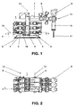
- the Fig.1 shows a schematic side view of a outgoing panel 1 of a single-phase metal-enclosed gas-insulated switchgear and the Fig.2 shows a plan view of this outgoing panel 1.
- This outlet box 1 has a support frame 2, which is made of a metal profile.
- a metal profile for example, I-profiles or pipe sections made of steel can be used.
- the tube profiles usually have a round or a rectangular cross-section.
- angle profiles 3 are attached, which serve the connection of the support frame 2 with a foundation 4.
- connection can be formed non-positively, but they can also allow sliding of the support frame 2 on a recessed into the foundation 4 and not shown here mounting rail.
- the busbars 5 are arranged vertically one above the other on one or both sides of the vertical pole of the circuit breaker 6.
- the outlet is provided with a current transformer 7, which is followed by a separator 8, which takes over the function of the outgoing separator.
- an earth electrode is provided in each case.
- a voltage converter 9 is provided.
- a cable connection 10 connects the outgoing high-voltage cable 11 with the gas-insulated switchgear. An intended for a feed field is similar to the described outgoing field. 1
- the busbars 5 each have a busbar axis 12.
- the busbar axles 12 of each of the two busbar systems are vertically superimposed in a plane.
- the poles of the circuit breaker 6 each have a pole axis 13.
- the pole axes 13 of the three circuit breaker poles lie in a plane which is perpendicular to the foundation 4.
- the planes in which the busbar systems are located and the plane in which the polar axes 13 lie are arranged parallel to one another in this outgoing area 1.
- the leading away from the respective circuit breaker pole part of the outgoing panel 1, the current transformer 7, the separator 8 and the housing to which the cable connection 10 is flanged extends along a longitudinal axis 14.
- the longitudinal axis 14 is perpendicular to the respective pole axis 13.
- Der vom Kunststoffmaschinen GmbHer der Kunststoffer leading part of the departure may be in the direction as in Fig.1 shown, but it may also extend in the opposite direction.
- the upper part of the Polgeophuses can be aligned during assembly accordingly. In general, a rotation is made by 180 ° about the pole axis 13, but it is also possible to turn off the upper part of the pole housing by an angle in the range of 180 °. Since the power switch 6 is provided with a separate drive per pole, each of the three poles may have differently oriented outlets.
- connection from the respective circuit breaker pole to the bus bars extends along a connection axis 15 Fig.1 It can be seen that in this equipped with a double busbar outgoing field 1 only one earthing 16 per connection is provided. In this gas-insulated switchgear one of the normally required in this area two earth electrode, without a loss saved on safety and without reducing the availability of the system.
- the earth electrode 16 can be installed in a switchgear with dual busbar system either on one side or on the other side of the circuit breaker pole.
- the space provided on one side of the circuit breaker pole for the earthing is sufficient to close the pole housing pressure-tight with a cover; enough space remains for the busbar so that the busbar axis 12 remains unchanged even in a dome panel can be maintained compared to the feed and exit fields.
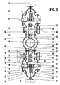
- the Figure 3 shows a schematic representation of the in Fig.1 registered section AA.
- the polar axis 13 is perpendicular to the cutting plane, it penetrates these in a central point 17.
- a cylindrically shaped housing bottom 18 which extends along the Polachse 13 is provided with two on the connecting axis 15 as the center lying, not designated openings, respectively are flanged pressure-tight with a cylindrically shaped, disk-shaped partition insulator 19,20.
- the insulation insulator 19 has a power connection 21 penetrating it in the center.
- the bulkhead insulator 20 has a power connection 22 penetrating it in the center.
- an electrically conductive connector 23 is screwed, which is surrounded by a dielectrically favorable designed shield 24.
- the connecting piece 23 is firmly screwed to a contact ring 25 made of a good electrically conductive metal.
- the connector 23 and the contact ring 25 may also be integrally formed.
- the contact ring 25 has on the opposite side of the connector 23 on a screwed with him contact assembly 26.
- the power connector 21 is connected to a contact carrier 27, which is equipped, for example, with spiral contacts.
- the contact assembly 26 encloses the contact carrier 27 and forms with him a releasable plug contact, which is surrounded by a dielectrically favorable designed shield 28.
- the center of the contact ring 25 coincides with the central point 17.
- the cylindrically shaped inner surface of the contact ring 25 is provided with at least one groove, not shown, in which an unillustrated plastic ring is glued.
- the plastic ring leads to the installation of the quenching chamber, the electrically conductive exhaust housing thereof, which is externally equipped with elastic contact elements, for example with spiral contacts that make contact with the contact ring 25, and it prevents the elastic contact elements are subjected to an asymmetrical mechanical stress.
- the central inner opening of the contact ring 25 receives the exhaust housing connected to the quenching chamber.
- the housing 29 of a separator designed as an angle separator 30 is flanged pressure-tight.
- the connector 23 is provided with a screw 23 a threaded hole, which also penetrates the contact ring 25.
- the screw 23a serves the non-positive connection of the connecting piece 23, or the contact ring 25 with the exhaust housing of the quenching chamber after it has been inserted into the contact ring 25.
- the simplified illustrated housing 29 of the separator 30 has a wall of metal. As a rule, the housing 29 is pressure-sealed from an aluminum alloy. The housing 29 has, in addition to the closed with the partition insulator 19 opening on five other non-designated with flanges 31 to 35 openings. The housing 29 also has a longitudinal axis which coincides with the connection axis 15.
- the opening provided with the flange 31 is provided in the separator mounting with a metallic cover 36 having a flange 37 which is bolted to the flange 31 gas-tight. Opposite the flange 37, a further flange 38 is attached to the cover 36.
- the flange 38 is used to attach a pressure-resistant passage for a movable in a switching operation of the separator 30 in the direction of a coincidence with the axis 15 actuating axis movable Isolierstoffstange 39.
- the Isolierstoffstange 39 moves, driven by a likewise connected to the flange 38 disconnector drive 40, the strong
- the moveable contact arrangement 41 is surrounded by a dielectrically active shield 42, which is penetrated by the insulating rod 39.
- a non-designated busbar housing is flanged. Flanged to the flange 33 is a barrier insulator 43, which is penetrated by a power connection 44. To the power connector 44, a conductor piece 45 is screwed, which is coated on the insulator side by a dielectrically active shield 46. The conductor piece 45 extends along the busbar axis 12, which is perpendicular to the connection axis 15. The conductor piece 45 is electrically conductively connected to a first fixed contact carrier 47 of the separator 30. In the contact carrier 47, a sliding contact 48 is inserted, which is provided for the passage of current from the movable contact assembly 41 of the separator 30 to the contact carrier 47.
- the sliding contact 48 is arranged concentrically to the connection axis 15, it is provided with contact fingers, with contact blades or with spiral contacts.
- the contact carrier 47 is arranged concentrically to the connection axis 15.
- the contact carrier 47 is simultaneously formed as part of the busbar active parts.
- the power connector 21 is electrically connected to a second fixed contact carrier 50 of the separator 30.
- the insulator end of the contact carrier 50 is covered with a dielectrically effective shield 51.
- the contact carrier 47 facing the end of the contact carrier 50 is provided with a concentric with the connection axis 15 arranged mating contact 52 for the movable contact assembly 41 of the separator 30.
- the contact carrier 47 and 50 are formed dielectrically favorable, any edges are executed rounded.
- the power terminals 44 and 21 are in operation at high voltage potential and are insulated from the metal enclosure of the gas-insulated switchgear.
- a tulip-shaped counter contact 53 is also inserted, which is arranged concentrically to a mounting axis 54 and which receives the contact pin 55 of the earthing 16 when the earthing 16 is closed.
- the mounting axis 54 is perpendicular to the connection axis 15.
- a distance 56 is between the contact carrier 47 and the mating contact 52. This distance 56 corresponds to the separation distance of the separator 30 which withstands all operational stresses occurring during operation at this point.
- the movable contact arrangement 41 When the disconnector 30 is switched on, the movable contact arrangement 41 is moved toward the mating contact 52 along the connection axis 15 as a result of the insulator bar 39 actuated by the disconnector drive 40.
- An optionally caused by residual charges and / or by an applied between the contact carrier 47 and the mating contact 52 operating frequency voltage pre-ignition between the movable contact assembly 41 and the mating contact 52 is properly controlled by the separator 30.
- An expansion of the Vorzüllingtbogens to the wall of the housing 29 may not occur due to the geometric arrangement of the contact carrier 47 and the mating contact 52.
- the disconnector drive 40 is designed so that it moves the movable contact assembly 41 securely in each envisaged operating position in the intended switch-on, so that a proper power supply over the designated, unspecified rated current contacts is guaranteed. Likewise, the opening of the separator 30 is always properly.
- the earth 16 is installed in the provided with the flange 34 opening.
- it could also be installed alternatively in the provided with the flange 35 opening.
- a rupture disk 57 are flanged pressure-tight, which allows a pressure relief of the housing 29 in case of failure.
- the two flanges 34 and 35 have a common mounting axis 54.
- the flanged on the other side of the housing base 18 housing 58 corresponds to almost all the mounting parts of the housing 29, it is only arranged in mirror image to this, and there is no ground installed.
- a contact carrier 62 electrically connected, which carries a mating contact 63 of the right-hand separator arranged.
- the separator 30 can be installed in any mounting position, which is determined by the plant concept of the metal-enclosed gas-insulated switchgear.
- the earth electrode 16 can also be actuated position-independent, so that therefore there are no installation restrictions.
- the earth electrode 16 can be designed both as a worker's earth and as a fastder.
- the assembly separator 30 with upstream earthing 16 is designed very compact and takes up very little space in the direction of the connecting axis 15, so that the panel can be performed with very small dimensions.
- the open separation section of the isolator is highly reliable isolated by means of SF 6 .
- the isolator In the closed state, the isolator has an optimum rated current carrying capacity, a very good short-circuit current carrying capacity and surge current resistance. Furthermore, it has a reliable switching capacity with small capacitive currents, it also dominates the switching in an uninterruptible busbar change.
- the disconnector 30 has separate contact systems for the continuous current flow and for the actual switching operation.
- the continuous current contacts are designed simply and reliably, they have a minimum number of individual parts.
- the contact movement is carried out by means of an electrically operated, outside the SF 6 gas filled separator housing arranged Trennerantriebs, but the separator can also be driven by hand.
- Such a configuration facilitates the maintenance work very advantageous.
- the separator 30 is provided with a mechanically coupled position indicator, further, a sight glass may be provided for an endoscope for controlling the position of the contacts of the separator 30th
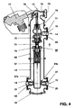
- the Figure 4 shows a simplistic schematic representation of in Fig.2 registered section BB through a first pole of the circuit breaker 6.
- This pole has a metallic, insulating gas filled pole housing, which is composed of several components, which are pressure-tightly interconnected.
- the pole housing has a lower housing part 18 which is closed at the bottom with a cover flange 64 and which is of the same design in all three poles of a three-pole circuit breaker 6, but which is used in a different mounting position.
- each a contacting assembly 65 is installed in the lower housing part 18 .
- This contacting assembly 65 each consists of those associated with Figure 3 described parts such as the connector 23 with the shield 24, the contact ring 25, the contact assembly 26 and the contact carrier 27 with the shield 28.
- the Kunststoffssen istsbaud 65 is plugged on the one hand to the power connector 21 of the partition insulator 19 and on the other hand to the power connector 22 of the partition insulator 20th firmly connected.
- the circuit breaker pole has a quenching chamber 66, which has a cylindrically formed, made of metal and arranged concentrically to the pole axis 13 exhaust housing 67 which is retracted into the contacting assembly 65 and is electrically connected thereto via sliding contacts such as spiral contacts.
- the exhaust housing 67 transmits the potential of the contacting assembly 65 to the lower part of the quenching chamber 66 and simultaneously carries the operating current when the circuit breaker pole is closed.
- the exhaust housing 67 has a collar 67a, with which it is supported on the contact ring 25 of the contacting assembly 65.
- the collar 67a or the contact ring 25 is provided at the support point with an insulating coating that prevents a current transfer at this point.
- the contacting assembly 65 carries a portion of the weight of the quenching chamber 66 and also receives the resulting from the moving contacts of the quenching chamber 66 reaction forces.
- a housing upper part 68 is pressure-tight, which has a pressure-tight with a barrier insulator 69, not designated opening.
- the Schottungsisolator 69 has a current connection 70 penetrating it, which is connected on the one hand with the not shown, extending in the direction of the longitudinal axis 14, active parts of the outgoing electrically conductive, and the other via a contact piece 71 with the upper part 72 of the quenching chamber 66 is connected, usually a screw is provided here.
- the upper part 72 and the lower part 73 of the quenching chamber 66 are connected by an insulating nozzle 74 to a unit.
- the insulating nozzle 74 when the circuit breaker pole is turned off, isolates the upper part 72 from the lower part 73. An additional connection of the upper part 72 to the lower part 73 by means of an insulating tube is not necessary here. The saving of this insulating brings economic benefits.
- the quenching chamber 66 is held in the center of the pole housing only by the screw connection with the contact piece 71 and by the contacting assembly 65.
- a housing cover 75 is connected to the housing upper part 68 and closes the pole housing upwards.
- the housing cover 75 is provided with a rupture disk 76, which can escape in the case of an emergency resulting in the pole housing overpressure into the environment.
- a drive 77 is flanged for the circuit breaker pole.
- the drive 77 is not seated on the polar axis 13, it is arranged next to the pole housing, in this case on the outlet to the cable connection 10 opposite side of the pole housing.
- the height of the dressschalterpols is not or only slightly increased by the drive 77.
- the drive 77 acts via a schematically indicated force conversion to an insulating actuating rod 78, which moves the movable contact parts of the quenching chamber 66 along the pole axis 13.
- a guide member 79 is formed, which guides the insulating actuating rod 78 along the polar axis 13.
- the quenching chamber 66 is inserted as a whole from above along the polar axis 13 in the pole housing so that the exhaust housing 67 gets in perfect contact with the contacting assembly 65, and that the contact piece 71, after it is screwed, also the active parts of the outlet reliably electrically connected to the upper part 72 of the quenching chamber 66. Finally, the screw 23a is then tightened so that the quenching chamber 66 is fixed in two places.
- Other positions of the polar axis 13 are also conceivable, in particular, in the case of appropriately designed gas-insulated switchgear, the horizontal position.
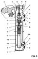
- the Figure 5 shows a section through a pole of a circuit breaker 6, which is constructed similar to that in Figure 4 shown, however, in this circuit breaker 6, the installation of the left busbar system is not provided, resulting in a particularly economical configuration of the outgoing panel.
- the contacting assembly 80 is designed somewhat simpler in this embodiment, since only a busbar system with the exhaust housing 67 must be connected. Furthermore, the lower housing part 18a has no opening for contacting with a second busbar system.
- the remaining components of this circuit breaker 6 are identical, as already related to Figure 4 described parts.
- An additional connection of the upper part 72 of the quenching chamber 66 with the lower part 73 by means of an insulating tube is also not necessary here. The saving of this insulating brings economic Benefits with it.
- the quenching chamber 66 is held in the center of the pole housing only by the screw connection with the contact piece 71 and by the modified contacting assembly 80.
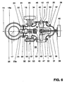
- the Figure 6 shows a schematic representation of the in Fig.1 registered section AA, as in the simplified executed outgoing field according to Figure 5 represents. Since only the right busbar system is contacted here, the lower housing part 18a has only one contacting possibility. the earth electrode 16 is arranged between the power switch 6 and the disconnector 30. The structure of the separator 30 designed as an angle separator has already been described in connection with FIG Figure 3 described embodiment variant described. Again, a provided with a screw 23 a threaded hole is incorporated in the connecting piece 23, which also penetrates the contact ring 25. The screw 23a serves the non-positive connection of the connecting piece 23, or the contact ring 25, with the exhaust housing of the quenching chamber, after this has been introduced into the contact ring 25.
- the pole axes 13 are arranged in a plane.
- the pole axes 13 are perpendicular to the foundation 4.
- the busbar axes 12 of a busbar system are also arranged in a plane perpendicular to the foundation 4, but the busbar axes 12 extend parallel to the surface of the foundation 4.
- this can be arranged either on one side or on the other side of the plane of the pole axes 13 of the circuit breaker 6, when the lower housing part 18a is rotated by 180 ° around the Polachse 13 accordingly.
- the gas-insulated switchgear is equipped with a double busbar system busbar system, they are usually arranged on both sides of the plane of the pole axes 13 of the circuit breaker 6 and equidistant from this.
- the busbars 5 in parallel to the pole axes 13 of the circuit breaker 6 levels a particularly space-saving arrangement of the busbar connections is possible, they can be arranged on a diagonal.
- a particularly compact arrangement of the gas-insulated switchgear arises when the distance between adjacent busbar shafts 12, exactly the same size as the distance between adjacent pole axes 13 is selected.
Landscapes
- Engineering & Computer Science (AREA)
- Power Engineering (AREA)
- Gas-Insulated Switchgears (AREA)
Description
Die Erfindung geht aus von einer metallgekapselten gasisolierten Schaltanlage gemäss dem Oberbegriff des Anspruchs 1.The invention relates to a metal-enclosed gas-insulated switchgear according to the preamble of
Eine derartige metallgekapselte gasisolierte Schaltanlage kann dem AEG-Prospekt "Gasisolierte Schaltanlagen, Baureihe B1-02, 72,5 - 145kV entnommen werden.Such a metal-enclosed gas-insulated switchgear can be found in the AEG brochure "Gas-insulated switchgear, series B1-02, 72.5 - 145kV.
Es sind einphasig metallgekapselte gasisolierte Schaltanlagen bekannt, deren Leistungsschalterpole Löschkammern aufweisen, die durch speziell ausgebildete Stützeranordnungen aus Isoliermaterial gehalten und gegen das als Metallkapselung ausgebildete Polgehäuse abgestützt werden. Jede dieser Stützeranordnungen ist vergleichsweise aufwendig und teuer herzustellen. Die Stromanschlüsse dieser Löschkammern werden in der Regel ebenfalls durch separate weitere Stützer in der Metallkapselung gehalten, wobei dieser Stützertyp als Standardbauteil an einer Vielzahl von Stellen in der gasisolierten Schaltanlage eingesetzt wird. Wegen der vergleichsweise grossen Stückzahlen lässt sich dieser Stützertyp überaus günstig herstellen.There are known single-phase metal-enclosed gas-insulated switchgear whose circuit breaker poles have extinguishing chambers which are held by specially trained Stützeranordnungen of insulating material and supported against the formed as a metal encapsulation Polgehäuse. Each of these support arrangements is comparatively complicated and expensive to produce. The power connections of these extinguishing chambers are usually also held by separate other supporters in the metal enclosure, this type of support is used as a standard component at a variety of locations in the gas-insulated switchgear. Because of the relatively large numbers, this type of supporter can be produced very low.
Ferner sind die Teile der Löschkammer, die beidseitig der Unterbrechungsstelle der Löschkammer liegen, in der Regel durch ein druckfestes Isolierrohr verbunden, welches vergleichsweise aufwendig herzustellen ist.Furthermore, the parts of the quenching chamber, which are located on both sides of the interruption point of the quenching chamber, usually connected by a pressure-resistant insulating tube, which is relatively expensive to produce.
Die Offenlegungsschrift
Die Patentanmeldung
Die Erfindung, wie sie in dem unabhängigen Anspruch gekennzeichnet ist, löst die Aufgabe, eine metallgekapselte gasisolierte Schaltanlage zu schaffen, bei welcher die Isolation und die Befestigung der Löschkammern der Leistungsschalterpole wesentlich vereinfacht und verbilligt ist.The invention, as characterized in the independent claim, solves the problem of providing a metal-enclosed gas-insulated switchgear in which the isolation and attachment of the extinguishing chambers of the circuit breaker poles is much easier and cheaper.
Mit der vorliegenden Erfindung wird eine metallgekapselte gasisolierte Schaltanlage bereitgestellt mit mindestens einem Sammelschienensystem, mit einem Leistungsschalter, der pro Pol jeweils eine Polachse und mindestens eine in ein als Metallkapselung ausgebildetes Polgehäuse eingebaute Löschkammer aufweist, mit mindestens einem oberen und mindestens einem unteren Stromanschluss pro Leistungsschalter, von denen jeder mittels eines separaten Isolators kraftschlüssig mit dem Polgehäuse verbunden ist, und mit jeweils einer entlang einer Verbindungsachse erstreckten, elektrisch leitenden, kraftschlüssigen Verbindung der spannungsführenden Löschkammer des jeweiligen Pols mit der jeweils zugeordneten Sammelschiene, wobei die elektrisch leitende Verbindung des mindestens einen unteren Stromanschlusses eine im Innern des Polgehäuses angeordnete Kontaktierungsbaugruppe aufweist, die mit einem die Polachse konzentrisch umgebenden Kontaktring versehen ist.With the present invention, a metal-enclosed gas-insulated switchgear is provided with at least one busbar system, with a circuit breaker which has one polar axis per pole and at least one arcing chamber installed in a pole housing designed as a metal encapsulation, with at least one upper and at least one lower electrical connection per circuit breaker. each of which is connected by means of a separate insulator frictionally connected to the pole housing, and each having a along a connecting axis extending, electrically conductive, non-positive connection of the voltage-carrying quenching chamber of the respective pole with the respective associated busbar, wherein the electrically conductive connection of the at least one lower power connector a arranged in the interior of the pole housing contacting assembly, which is provided with a pole axis concentrically surrounding the contact ring.
Bei dieser Schaltanlage kontaktiert der Kontaktring im Innern ein mit der Löschkammer elektrisch leitend verbundenes Auspuffgehäuse, weist das Auspuffgehäuse aussen einen Bund auf, stützt sich der Bund auf den Kontaktring ab und ist die Löschkammer bei der Montage als Ganzes entlang der jeweiligen Polachse von oben in das Polgehäuse einfahrbar.In this switchgear contacts the contact ring in the interior of an electrically connected to the extinguishing chamber exhaust housing, the exhaust housing has a collar on the outside, the collar is based on the contact ring and is the extinguishing chamber during assembly as a whole along the respective pole axis from above in the Pol housing retractable.
In fertigungstechnisch vorteilhafter Weise kann die Löschkammer bei der Montage dieser Schaltanlage als Ganzes entlang der Polachse von oben ins Polgehäuse eingefahren und an zwei Stellen im Polgehäuse fixiert werden, zum einen am oberen Stromanschluss und zum anderen an der Kontaktierungsbaugruppe. Besonders günstig im Hinblick auf die Wirtschaftlichkeit der gasisolierten Schaltanlage wirkt es sich aus, dass die Löschkammer kraftschlüssig mit den mindestens zwei Stromanschlüssen verbunden ist, und dass die Löschkammer allein durch diese in dem als Metallkapselung ausgebildeten Polgehäuse positioniert wird. Speziell ausgebildete Stützeranordnungen aus Isoliermaterial, welche die Löschkammer halten und direkt gegen das als Metallkapselung ausgebildete Polgehäuse abstützen, sind bei der erfindungsgemässen Ausgestaltung des Leistungsschalters nicht nötig.In manufacturing technology advantageously, the extinguishing chamber can be retracted in the assembly of this switchgear as a whole along the pole axis from above into the pole housing and fixed in two places in the pole housing, on the one hand to the upper power connector and the other to the Kontaktierungsbaugruppe. With particular regard to the economy of the gas-insulated switchgear, it has the effect that the extinguishing chamber is positively connected to the at least two electrical connections, and that the extinguishing chamber is positioned solely by the latter in the pole housing designed as a metal encapsulation. Specially trained Stützeranordnungen of insulating material, which hold the quenching chamber and are supported directly against the formed as a metal encapsulation pole housing, are not necessary in the inventive design of the circuit breaker.
Die elektrisch leitende Verbindung weist eine im Innern des Polgehäuses angeordnete Kontaktierungsbaugruppe mit einem Kontaktring auf, wobei der Kontaktring die Polachse des Leistungsschalters konzentrisch umgibt. Der Kontaktring kontaktiert im Innern ein mit der Löschkammer elektrisch leitend verbundenes Auspuffgehäuse, welches aussen einen Bund aufweist, der sich auf den Kontaktring abstützt. Der Kontaktring ist bei einer Ausgestaltung der Erfindung einerseits über ein Verbindungsstück fest mit einem einen ersten Schottungsisolator durchdringenden ersten Stromanschluss verbunden und andererseits steckbar mit einem einen zweiten Schottungsisolator durchdringenden zweiten Stromanschluss. Bei einer zweiten Ausgestaltung der Erfindung sind Mittel vorgesehen, um das Auspuffgehäuse im Kontaktring zu fixieren.The electrically conductive connection has a contacting assembly arranged in the interior of the pole housing with a contact ring, wherein the contact ring concentrically surrounds the pole axis of the circuit breaker. The contact ring contacted in the interior of an electrically conductive with the quenching chamber exhaust housing, which has a collar outside, which is supported on the contact ring. The contact ring is in one embodiment of the invention on the one hand via a connector firmly connected to a first insulation isolator penetrating first power connector and on the other hand pluggable with a second Schottungsisolator penetrating second power connector. In a second embodiment of the invention means are provided to fix the exhaust housing in the contact ring.
Eine weitere vorteilhafte Verbilligung des Leistungsschalters ergibt sich dadurch, dass ein oberer Teil und ein unterer Teil der Löschkammer beim Einbau in das Polgehäuse lediglich mittels einer Isolierdüse zusammengehalten werden. Bedingt durch diese einfache Bauweise wird die Montage der Löschkammer etwas aufwendiger. Das üblicherweise verwendete und in der Regel teuere Löschkammerisolierrohr kann hier jedoch eingespart werden, was weitere wirtschaftliche Vorteile mit sich bringt.A further advantageous cheapening of the circuit breaker results from the fact that an upper part and a lower part of the extinguishing chamber are held together when installed in the pole housing only by means of an insulating nozzle. Due to this simple design, the assembly of the quenching chamber is a little more expensive. However, the usually used and usually expensive Löschkammerisolierrohr can be saved here, which brings further economic benefits.
Die weiteren Ausgestaltungen der Erfindung sind Gegenstände der weiteren abhängigen Ansprüche.The further embodiments of the invention are objects of the further dependent claims.
Die Erfindung, ihre Weiterbildung und die damit erzielbaren Vorteile werden nachstehend anhand der Zeichnung, welche lediglich einen möglichen Ausführungsweg darstellt, näher erläutert.The invention, its development and the advantages that can be achieved with it are explained in more detail below with reference to the drawing, which represents only one possible embodiment.
Es zeigen:
-
Fig.1 eine Seitenansicht eines Abgangsfeldes einer gasisolierten Schaltanlage, -
Fig.2 eine Draufsicht auf ein Abgangsfeld einer gasisolierten Schaltanlage, -
Fig.3 eine schematische Darstellung des inFig.1 eingetragenen Schnittes A-A, -
Fig.4 eine schematische Darstellung des inFig.2 eingetragenen Schnittes B-B, -
Fig.5 eine schematische Darstellung des inFig.2 eingetragenen Schnittes B-B, allerdings ist bei diesem Abgangsfeld das linke Sammelschienensystem weggelassen worden, und -
Fig.6 eine schematische Darstellung des inFig.1 eingetragenen Schnittes A-A, wie er sich bei dem vereinfacht ausgeführten Abgangsfeld gemässFig.5 darstellt.
-
Fig.1 a side view of a departure box of a gas-insulated switchgear, -
Fig.2 a top view of a departure field of a gas-insulated switchgear, -
Figure 3 a schematic representation of the inFig.1 registered section AA, -
Figure 4 a schematic representation of the inFig.2 registered section BB, -
Figure 5 a schematic representation of the inFig.2 registered section BB, however, the left busbar system has been omitted in this output field, and -
Figure 6 a schematic representation of the inFig.1 registered section AA, as in the simplified executed outgoing field according toFigure 5 represents.
Bei allen Figuren sind gleich wirkende Elemente mit gleichen Bezugszeichen versehen. Alle für das unmittelbare Verständnis der Erfindung nicht erforderlichen Elemente sind nicht dargestellt.In all figures the same elements are provided with the same reference numerals. All elements not required for the immediate understanding of the invention are not shown.
Die
Diese Verbindung kann kraftschlüssig ausgebildet sein, sie kann jedoch auch ein Gleiten des Tragrahmens 2 auf einer in das Fundament 4 eingelassenen und hier nicht dargestellten Tragschiene zulassen. Bei diesem Typ einer metallgekapselten und gasisolierten Schaltanlage sind die Sammelschienen 5 senkrecht übereinander an einer oder an beiden Seiten der senkrecht gestellten Pole des Leistungsschalters 6 angeordnet. Der Abgang ist mit einem Stromwandler 7 versehen, dem ein Trenner 8, der die Funktion des Abgangstrenners übernimmt, nachgeschaltet ist. Beidseits des Trenners 8 ist jeweils ein Erder vorgesehen. Nach dem Trenner 8 ist ein Spannungswandler 9 vorgesehen. Ein Kabelanschluss 10 verbindet das abgehende Hochspannungskabel 11 mit der gasisolierten Schaltanlage. Ein für eine Einspeisung vorgesehenes Feld ist ähnlich ausgebildet wie das beschriebene Abgangsfeld 1.This connection can be formed non-positively, but they can also allow sliding of the
Die Sammelschienen 5 weisen jeweils eine Sammelschienenachse 12 auf. Die Sammelschienenachsen 12 eines jeden der beiden Sammelschienensysteme liegen in einer Ebene senkrecht übereinander. Die Pole des Leistungsschalters 6 weisen jeweils eine Polachse 13 auf. Die Polachsen 13 der drei Leistungsschalterpole liegen in einer Ebene, die senkrecht zum Fundament 4 steht. Die Ebenen in denen die Sammelschienensysteme liegen und die Ebene in der die Polachsen 13 liegen, sind bei diesem Abgangsfeld 1 parallel zueinander angeordnet. Der vom jeweiligen Leistungsschalterpol wegführende Teil des Abgangsfelds 1, der Stromwandler 7, der Trenner 8 und das Gehäuse an welches der Kabelanschluss 10 angeflanscht ist, erstreckt sich entlang einer Längsachse 14. Die Längsachse 14 steht senkrecht auf der jeweiligen Polachse 13. Der vom Leistungsschalter 6 wegführende Teil des Abgangs kann sich in die Richtung, wie in
Bei einem Speisefeld, welches ähnlich dem Abgangsfeld 1 aufgebaut ist, und bei welchem sich entlang der jeweiligen Längsachse 14 die Einspeisung erstreckt, beispielsweise bis hin zu Durchführungen, die mit einer Freileitung verbunden sind, wirkt sich diese Möglichkeit des Drehens des oberen Teils des Polgehäuses besonders vorteilhaft aus, da auf diese Art auch in Schaltanlagen mit beengten Raumverhältnissen für die Einführung der Frei leitung hinreichende Phasenabstände einfach zu realisieren sind.In a feed field, which is constructed similar to the
Die Verbindung von dem jeweiligen Leistungsschalterpol zu den Sammelschienen erstreckt sich entlang einer Verbindungsachse 15. Aus der
Wird das Schaltfeld als Kuppelfeld aufgebaut, so reicht der auf der einen Seite des Leistungsschalterpols für den Erder vorgesehene Platz aus, um das Polgehäuse mit einem Deckel druckdicht zu verschliessen, für die Sammelschiene bleibt noch genug Platz, sodass auch in einem Kuppelfeld die Sammelschienenachse 12 unverändert im Vergleich zu den Speise- und den Abgangsfeldern beibehalten werden kann.If the panel is constructed as a dome field, the space provided on one side of the circuit breaker pole for the earthing is sufficient to close the pole housing pressure-tight with a cover; enough space remains for the busbar so that the
Die
Das Zentrum des Kontaktrings 25 fällt mit dem zentralen Punkt 17 zusammen. Die zylindrisch ausgebildete Innenfläche des Kontaktrings 25 ist mit mindestens einer nicht dargestellten Nut versehen, in welche ein nicht dargestellter Kunststoffring eingeklebt ist. Der Kunststoffring führt beim Einbau der Löschkammer das elektrisch leitende Auspuffgehäuse derselben, welches aussen mit elastischen Kontaktelementen bestückt ist, beispielsweise mit Spiralkontakten, die mit dem Kontaktring 25 einen elektrischen Kontakt herstellen, und er verhindert, dass die elastischen Kontaktelemente einer unsymmetrischen mechanischen Belastung unterworfen werden. Die zentrale innere Öffnung des Kontaktrings 25 nimmt das mit der Löschkammer verbundene Auspuffgehäuse auf. Auf der dem Kontaktträger 27 entgegengesetzten Seite des Schottungsisolators 19 ist das Gehäuse 29 eines als Winkeltrenner ausgebildeten Trenners 30 druckdicht angeflanscht. In das Verbindungsstück 23 ist eine mit einer Schraube 23a versehene Gewindebohrung eingearbeitet, die auch den Kontaktring 25 durchdringt. Die Schraube 23a dient der kraftschlüssigen Verbindung des Verbindungsstücks 23, bzw. des Kontaktrings 25 mit dem Auspuffgehäuse der Löschkammer nachdem dieses in den Kontaktring 25 eingeführt worden ist.The center of the
Das vereinfacht dargestellte Gehäuse 29 des Trenners 30 weist eine Wandung aus Metall auf. In der Regel wird das Gehäuse 29 druckdicht aus einer Aluminiumlegierung gegossen. Das Gehäuse 29 weist ausser der mit dem Schottungsisolator 19 verschlossenen Öffnung fünf weitere nicht bezeichnete mit Flanschen 31 bis 35 versehene Öffnungen auf. Das Gehäuse 29 weist zudem eine Längsachse auf, welche mit der Verbindungsachse 15 zusammenfällt. Die mit dem Flansch 31 versehene Öffnung wird bei der Trennermontage mit einer metallischen Abdeckung 36 versehen, die einen Flansch 37 aufweist, der mit dem Flansch 31 gasdicht verschraubt wird. Gegenüber dem Flansch 37 ist an der Abdeckung 36 ein weiterer Flansch 38 angebracht. Der Flansch 38 dient der Befestigung einer druckfesten Durchführung für eine bei einem Schaltvorgang des Trenners 30 in Richtung einer mit der Verbindungsachse 15 zusammenfallenden Betätigungsachse bewegbaren Isolierstoffstange 39. Die Isolierstoffstange 39 bewegt, durch einen ebenfalls mit dem Flansch 38 verbundenen Trennerantrieb 40 angetrieben, die, stark schematisiert dargestellte, bewegliche Kontaktanordnung 41 des Trenners 30. Die bewegliche Kontaktanordnung 41 ist von einer dielektrisch wirksamen Abschirmung 42 umgeben, die von der Isolierstoffstange 39 durchdrungen wird.The simplified illustrated
An den Flansch 32 ist ein nicht bezeichnetes Sammelschienengehäuse angeflanscht. An den Flansch 33 ist ein Schottungsisolator 43 angeflanscht, der von einem Stromanschluss 44 durchdrungen wird. An den Stromanschluss 44 ist ein Leiterstück 45 angeschraubt, welches isolatorseitig von einer dielektrisch wirksamen Abschirmung 46 umhüllt wird. Das Leiterstück 45 erstreckt sich längs der Sammelschienenachse 12, die senkrecht zur Verbindungsachse 15 verläuft. Das Leiterstück 45 ist mit einem ersten feststehenden Kontaktträger 47 des Trenners 30 elektrisch leitend verbunden. In den Kontaktträger 47 ist ein Gleitkontakt 48 eingelassen, der für den Stromübergang von der beweglichen Kontaktanordnung 41 des Trenners 30 auf den Kontaktträger 47 vorgesehen ist. Der Gleitkontakt 48 ist konzentrisch zur Verbindungsachse 15 angeordnet, er ist mit Kontaktfingern, mit Kontaktlamellen oder mit Spiralkontakten versehen. Der Kontaktträger 47 ist konzentrisch zur Verbindungsachse 15 angeordnet. Der Kontaktträger 47 ist gleichzeitig als Teil der Sammelschienenaktivteile ausgebildet. Auf der dem Leiterstück 45 gegenüberliegenden Seite des Kontaktträgers 47 ist ein weiteres Leiterstück 49 angebracht, welches sich entlang der Sammelschienenachse 12 durch die mit dem Flansch 32 versehene Öffnung erstreckt. Der Stromanschluss 21 ist mit einem zweiten feststehenden Kontaktträger 50 des Trenners 30 elektrisch leitend verbunden. Das isolatorseitige Ende des Kontaktträgers 50 ist mit einer dielektrisch wirksamen Abschirmung 51 abgedeckt. Das dem Kontaktträger 47 zugewandte Ende des Kontaktträgers 50 ist mit einem konzentrisch zur Verbindungsachse 15 angeordneten Gegenkontakt 52 für die bewegliche Kontaktanordnung 41 des Trenners 30 versehen. Die Kontaktträger 47 und 50 sind dielektrisch günstig ausgeformt, etwaige Kanten sind abgerundet ausgeführt. Die Stromanschlüsse 44 und 21 liegen im Betrieb auf Hochspannungspotential und sind gegenüber der Metallkapselung der gasisolierten Schaltanlage isoliert.To the
In den Kontaktträger 50 ist zudem ein tulpenförmig ausgebildeter Gegenkontakt 53 eingelassen, der konzentrisch zu einer Einbauachse 54 angeordnet ist und der den Kontaktstift 55 des Erders 16 aufnimmt, wenn der Erder 16 geschlossen wird. Die Einbauachse 54 steht senkrecht auf der Verbindungsachse 15. Zwischen dem Kontaktträger 47 und dem Gegenkontakt 52 besteht bei offenem Trenner 30 ein Abstand 56. Dieser Abstand 56 entspricht der Trennstrecke des Trenners 30 die im Betrieb allen an dieser Stelle auftretenden betriebsbedingten Spannungsbeanspruchungen standhält.In the
Beim Einschalten des Trenners 30 wird durch die durch den Trennerantrieb 40 betätigte Isolierstoffstange 39 die bewegliche Kontaktanordnung 41 entlang der Verbindungsachse 15 auf den Gegenkontakt 52 zu bewegt. Eine gegebenenfalls durch Restladungen und/oder durch eine zwischen dem Kontaktträger 47 und dem Gegenkontakt 52 anliegende betriebsfrequente Spannung hervorgerufene Vorzündung zwischen der beweglichen Kontaktanordnung 41 und dem Gegenkontakt 52 wird durch den Trenner 30 einwandfrei beherrscht. Eine Ausweitung des Vorzündlichtbogens hin zur Wand des Gehäuses 29 kann, bedingt durch die geometrische Anordnung des Kontaktträgers 47 und des Gegenkontakts 52 nicht auftreten. Der Trennerantrieb 40 ist so ausgelegt, dass er in jedem möglichen Betriebsfall die bewegliche Kontaktanordnung 41 sicher in die vorgesehene Einschaltstellung bewegt, sodass eine einwandfreie Stromführung über die dafür vorgesehenen, nicht näher beschriebenen Nennstromkontakte gewährleistet ist. Ebenso erfolgt auch das Öffnen des Trenners 30 stets einwandfrei.When the
Hier ist der Erder 16 in die mit dem Flansch 34 versehene Öffnung eingebaut. Er könnte jedoch auch alternativ in die mit dem Flansch 35 versehene Öffnung eingebaut werden. An den Flansch 35 können beispielsweise Detektoren für die Überwachung der gasisolierten Schaltanlage oder, wie in
Das auf der anderen Seite des Gehäuseunterteils 18 angeflanschte Gehäuse 58 entspricht mit beinahe sämtlichen Einbauteilen dem Gehäuse 29, es ist lediglich spiegelbildlich zu diesem angeordnet, und es ist kein Erder eingebaut. Die mit einem Flansch 59 versehene Öffnung, in welche ein entlang einer Einbauachse 60 erstreckter Erder eingebaut werden könnte, ist mittels eines Deckels 61 druckdicht verschlossen. Ebenso ist auch der Gegenkontakt des Erders nicht eingebaut worden. Mit dem Stromanschluss 22 ist auf der dem Verbindungsstück 23 abgewandten Seite ein Kontaktträger 62 elektrisch leitend verbunden, der einen Gegenkontakt 63 des rechts angeordneten Trenners trägt. Der Einbau eines zweiten Erders ist hier nicht nötig, da der Gegenkontakt 63 und der Kontaktträger 62 stets, dank des elektrisch leitenden Kontaktrings 25, auf dem gleichen Potential liegen wie der Kontaktträger 50 und der Gegenkontakt 52, sodass es vollauf genügt, wenn diese Aktivteile bei Bedarf gemeinsam mit Hilfe des einzigen Erders 16 sicher geerdet werden.The flanged on the other side of the
Der Trenner 30 kann in jeder beliebigen Einbaulage eingebaut werden, die durch das Anlagenkonzept der metallgekapselten gasisolierten Schaltanlage vorgegeben wird. Der Erder 16 kann ebenfalls lageunabhängig betätigt werden, sodass auch von daher keine Einbaubeschränkungen bestehen. Der Erder 16 kann sowohl als Arbeitserder als auch als Schnellerder ausgebildet sein. Die Baugruppe Trenner 30 mit vorgeschaltetem Erder 16 ist sehr kompakt ausgeführt und beansprucht in Richtung der Verbindungsachse 15 besonders wenig Platz, sodass das Schaltfeld mit besonders kleinen Abbmessungen ausgeführt werden kann.The
Die offene Trennstrecke des Trenners ist mittels SF6 höchstzuverlässig isoliert. Der Trenner weist im geschlossenen Zustand eine optimale Nennstromtragfähigkeit, eine sehr gute Kurzschlussstromtragfähigkeit und Stossstromfestigkeit auf. Ferner weist er ein zuverlässiges Schaltvermögen bei kleinen kapazitiven Strömen auf, er beherrscht zudem das Umschalten bei einem unterbrechungslosen Sammelschienenwechsel.The open separation section of the isolator is highly reliable isolated by means of SF 6 . In the closed state, the isolator has an optimum rated current carrying capacity, a very good short-circuit current carrying capacity and surge current resistance. Furthermore, it has a reliable switching capacity with small capacitive currents, it also dominates the switching in an uninterruptible busbar change.
Der Trenner 30 weist getrennte Kontaktsysteme für die Dauerstromführung und für den eigentlichen Schaltvorgang auf. Die Dauerstromkontakte sind einfach und zuverlässig konstruiert, sie weisen eine minimale Anzahl von Einzelteilen auf. Die Kontaktbewegung erfolgt mittels eines elektrisch betriebenen, ausserhalb des mit SF6-Gas gefüllten Trennergehäuses angeordneten Trennerantriebs, der Trenner kann jedoch auch von Hand angetrieben werden. Eine derartige Konfiguration erleichtert die Wartungsarbeiten sehr vorteilhaft. Der Trenner 30 ist mit einer mechanisch gekoppelten Stellungsanzeige versehen, ferner kann ein Schauglas vorgesehen werden für ein Endoskop zur Kontrolle der Position der Kontakte des Trenners 30.The
Die
Auf das Gehäuseunterteil 18 ist ein Gehäuseoberteil 68 druckdicht aufgesetzt, welches eine mit einem Schottungsisolator 69 druckdicht verschlossene, nicht bezeichnete Öffnung aufweist. Der Schottungsisolator 69 weist einen ihn durchdringenden Stromanschluss 70 auf, der einerseits mit den nicht dargestellten, sich in Richtung der Längsachse 14 erstreckenden, Aktivteilen des Abgangs elektrisch leitend verbunden ist, und der andererseits über ein Kontaktstück 71 mit dem oberen Teil 72 der Löschkammer 66 fest verbunden ist, in der Regel wird hier eine Schraubverbindung vorgesehen. Der obere Teil 72 und der untere Teil 73 der Löschkammer 66 werden durch eine Isolierdüse 74 zu einer Einheit verbunden. Die Isolierdüse 74 isoliert, wenn der Leistungsschalterpol ausgeschaltet ist, den oberen Teil 72 vom unteren Teil 73. Eine zusätzliche Verbindung des oberen Teils 72 mit dem unteren Teil 73 mittels eines Isolierrohrs ist hier nicht nötig. Die Einsparung dieses Isolierrohrs bringt wirtschaftliche Vorteile mit sich. Die Löschkammer 66 wird lediglich durch die Schraubverbindung mit dem Kontaktstück 71 und durch die Kontaktierungsbaugruppe 65 im Zentrum des Polgehäuses gehalten. Ein Gehäusedeckel 75 wird mit dem Gehäuseoberteil 68 verbunden und schliesst das Polgehäuse nach oben ab. Der Gehäusedeckel 75 ist mit einer Berstscheibe 76 versehen, die im Notfall einen im Polgehäuse entstehenden Überdruck in die Umgebung entweichen lässt. An den Gehäusedeckel 75 ist ein Antrieb 77 für den Leistungsschalterpol angeflanscht. Der Antrieb 77 sitzt nicht auf der Polachse 13, er ist neben dem Polgehäuse angeordnet, und zwar hier auf der dem Abgang zum Kabelanschluss 10 entgegengesetzten Seite des Polgehäuses. Die Bauhöhe des Leistungsschalterpols wird so durch den Antrieb 77 nicht oder nur unwesentlich vergrössert. Der Antrieb 77 wirkt über eine schematisch angedeutete Kraftumsetzung auf eine isolierende Betätigungsstange 78 ein, welche die beweglichen Kontaktteile der Löschkammer 66 entlang der Polachse 13 bewegt. An den oberen Teil 72 der Löschkammer 66 ist ein Führungsteil 79 angeformt, welches die isolierende Betätigungsstange 78 entlang der Polachse 13 führt.On the
Bei der Montage wird die Löschkammer 66 als Ganzes von oben her entlang der Polachse 13 in das Polgehäuse so eingeführt, dass das Auspuffgehäuse 67 mit der Kontaktierungsbaugruppe 65 einwandfrei Kontakt bekommt, und dass das Kontaktstück 71, nachdem es verschraubt ist, ebenfalls die Aktivteile des Abgangs zuverlässig mit dem oberen Teil 72 der Löschkammer 66 elektrisch verbindet. Abschliessend wird dann noch die Schraube 23a angezogen, sodass die Löschkammer 66 an zwei Stellen fixiert ist. Es sind auch andere Positionen der Polachse 13 vorstellbar, insbesondere auch, bei entsprechend ausgebildeten gasisolierten Schaltanlagen, die waagrechte Position.During assembly, the quenching
Die
Die
Bei der erfindungsgemässen metallgekapselten gasisolierten Schaltanlage sind die Polachsen 13 in einer Ebene angeordnet. Die Polachsen 13 verlaufen hier senkrecht zum Fundament 4. Die Sammelschienenachsen 12 eines Sammelschienensystems sind ebenfalls in einer Ebene senkrecht zum Fundament 4 angeordnet, doch verlaufen die Sammelschienenachsen 12 parallel zu der Oberfläche des Fundaments 4. Wird eine gasisolierte Schaltanlage mit nur einem Sammelschienensystem erstellt, wie dies mit der Leistungsschalterausführung gemäss
Eine besonders kompakte Anordnung der gasisolierten Schaltanlage ergibt sich dann, wenn der Abstand zwischen benachbarten Sammelschienenachsen 12, genau gleich gross wie der Abstand zwischen benachbarten Polachsen 13 gewählt wird.A particularly compact arrangement of the gas-insulated switchgear arises when the distance between
- 11
- Abgangs feldDeparture field
- 22
- Tragrahmensupporting frame
- 33
- Winkelprofileangle sections
- 44
- Fundamentfoundation
- 55
- Sammelschienenbusbars
- 66
- Leistungsschalterbreakers
- 77
- StromwandlerPower converter
- 88th
- Trennerseparator
- 99
- SpannungswandlerDC converter
- 1010
- Kabelanschlusscable
- 1111
- HochspannungskabelHigh voltage cables
- 1212
- SammelschienenachsenBusbar axes
- 1313
- Polachsepolar axis
- 1414
- Längsachselongitudinal axis
- 1515
- Verbindungsachseconnecting axis
- 1616
- Erderearthing
- 1717
- zentraler Punktcentral point
- 1818
- GehäuseunterteilHousing bottom
- 18a18a
- GehäuseunterteilHousing bottom
- 19,2019.20
- Schottungsisolatorseparating insulator
- 21,2221.22
- Stromanschlusspower connection
- 2323
- Verbindungsstückjoint
- 23a23a
- Schraubescrew
- 2424
- Abschirmungshielding
- 2525
- Kontaktringcontact ring
- 2626
- KontaktanordnungContact configuration
- 2727
- Kontaktträgercontact support
- 2828
-
Abschirmung 28
Shield 28 - 2929
- Gehäusecasing
- 3030
- Trennerseparator
- 31 bis 3531 to 35
- Flanschflange
- 3636
- Abdeckungcover
- 37,3837.38
- Flanschflange
- 3939
- IsolierstoffstangeIsolierstoffstange
- 4040
- Trennerantriebdisconnector drive
- 4141
- bewegliche Kontaktanordnungmovable contact arrangement
- 4242
- Abschirmungshielding
- 4343
- Schottungsisolatorseparating insulator
- 4444
- Stromanschlusspower connection
- 4545
- Leiterstückconductor piece
- 4646
- Abschirmungshielding
- 4747
- Kontaktträgercontact support
- 4848
- Gleitkontaktsliding contact
- 4949
- Leiterstückconductor piece
- 5050
- Kontaktträgercontact support
- 5151
- Abschirmungshielding
- 52,5352.53
- Gegenkontaktcountercontact
- 5454
- EinbauachseMounting axis
- 5555
- Kontaktstiftpin
- 5656
- Abstanddistance
- 5757
- Berstscheiberupture disc
- 5858
- Gehäusecasing
- 5959
- Flanschflange
- 6060
- EinbauachseMounting axis
- 6161
- Deckelcover
- 6262
- Kontaktträgercontact support
- 6363
- Gegenkontaktcountercontact
- 6464
- Deckelflanschcover flange
- 6565
- Kontaktierungsbaugruppecontact-making
- 6666
- Löschkammerextinguishing chamber
- 6767
- Auspuffgehäuseexhaust housing
- 67a67a
- BundFederation
- 6868
- GehäuseoberteilHousing top
- 6969
- Schottungsisolatorseparating insulator
- 7070
- Stromanschlusspower connection
- 7171
- Kontaktstückcontact piece
- 7272
- oberer Teilupper part
- 7373
- unterer Teillower part
- 7474
- Isolierdüseinsulating
- 7575
- Gehäusedeckelhousing cover
- 7676
- Berstscheiberupture disc
- 7777
- Antriebdrive
- 7878
- Betätigungsstangeactuating rod
- 7979
- Führungsteilguide part
- 8080
- Kontaktierungsbaugruppecontact-making
Claims (7)
- Metal-enclosed gas-filled switchgear unit having at least one busbar system having a circuit breaker (6) which respectively has per pole one pole axis (13) and at least one arcing chamber (66) built into a pole housing (18, 18a, 68) constructed as a metal enclosure,
having at least one upper (70) and at least one lower current terminal (21, 22) per circuit breaker (6), of which each is connected in a force-closed fashion by means of a separate insulator (19, 20, 69) to the pole housing (18, 18a, 68), and having in each case an electrically conductive,
force-closed connection, extending along a connecting axis (15), between the live arcing chamber (66) of the respective pole and the respectively assigned busbar (5), the electrically conductive connection of the at least one lower current terminal (21, 22) having a contact subassembly (65, 80) which is arranged in the interior of the pole housing (18, 18a, 68) which is provided with a contact ring (25) which concentrically surrounds the pole axis (13), characterized- in that the contact ring (25) in the interior contacts an exhaust housing (67) which is connected in an electrically conductive fashion to the arcing chamber (66),- in that the exhaust housing (67) has on the outside a collar (67a),- in that the collar (67a) is supported on the contact ring (25), and- in that, during assembly, the arcing chamber (66) can be inserted as a whole into the pole housing (18, 18a, 68) from above along the respective pole axis (13). - Metal-enclosed gas-filled switchgear unit according to Claim 1, characterized in that- on the one hand, the contact ring (25) is permanently connected via a connecting piece (23) to a first current terminal (22) penetrating a first partition insulator (20), and- on the other hand, the contact ring (25) is pluggably connected to a second current terminal (21) penetrating a second partition insulator (19).
- Metal-enclosed gas-filled switchgear unit according to Claim 1, characterized in that- means are provided for fixing the exhaust housing (67) in the contact ring (25).
- Metal-enclosed gas-filled switchgear unit according to Claim 1, characterized in that- the upper current terminal (70) of the arcing chamber (66) has a contact piece (71) which is connected in a force-closed fashion to an upper part (72) of the arcing chamber (66).
- Metal-enclosed gas-filled switchgear unit according to Claim 1, characterized in that- the pole axes (13) are arranged perpendicular to a foundation (4), and- the arcing chamber (66) is configured in a fashion capable of being withdrawn upwards out of the pole housing along the respective pole axis (13).
- Metal-enclosed gas-filled switchgear unit according to Claim 1, characterized in that- an upper part (72) and a lower part (73) of the arcing chamber (66) are held together by means of an insulating nozzle (74).
- Metal-enclosed gas-filled switchgear unit according to Claim 1, characterized in that- means are provided for electrically insulating the collar (67a) from the contact ring (25).
Applications Claiming Priority (2)
| Application Number | Priority Date | Filing Date | Title |
|---|---|---|---|
| DE4420524A DE4420524A1 (en) | 1994-06-13 | 1994-06-13 | Metal-encapsulated gas-insulated switchgear |
| DE4420524 | 1994-06-13 |
Publications (3)
| Publication Number | Publication Date |
|---|---|
| EP0688071A1 EP0688071A1 (en) | 1995-12-20 |
| EP0688071B1 EP0688071B1 (en) | 1999-08-18 |
| EP0688071B2 true EP0688071B2 (en) | 2013-08-28 |
Family
ID=6520410
Family Applications (1)
| Application Number | Title | Priority Date | Filing Date |
|---|---|---|---|
| EP95810357.4A Expired - Lifetime EP0688071B2 (en) | 1994-06-13 | 1995-05-31 | Metal-clad gas-insulated switchgear |
Country Status (6)
| Country | Link |
|---|---|
| US (1) | US5578805A (en) |
| EP (1) | EP0688071B2 (en) |
| CN (1) | CN1045033C (en) |
| BR (1) | BR9502775A (en) |
| CA (1) | CA2147085A1 (en) |
| DE (2) | DE4420524A1 (en) |
Families Citing this family (27)
| Publication number | Priority date | Publication date | Assignee | Title |
|---|---|---|---|---|
| DE4438776C1 (en) * | 1994-10-21 | 1996-04-11 | Siemens Ag | Metal-enclosed electrical high-voltage switchgear with a circuit breaker |
| DE29608127U1 (en) * | 1996-04-29 | 1996-07-11 | Siemens AG, 80333 München | Single or multi-pole, metal-encapsulated, partitioned or gas-insulated switchgear panels with viewing window |
| DE19632574A1 (en) * | 1996-08-13 | 1998-02-19 | Abb Patent Gmbh | Disconnect earth switch for a metal-enclosed, gas-insulated high-voltage switchgear |
| DE19634251A1 (en) * | 1996-08-26 | 1998-03-05 | Abb Patent Gmbh | Voltage converter |
| DE19805705A1 (en) * | 1998-02-06 | 1999-08-12 | Asea Brown Boveri | Gas-insulated metal-enclosed switchgear |
| FR2834138B1 (en) * | 2001-12-21 | 2004-11-12 | Alstom | ARMORED POSITION ELEMENT ON THE GROUND |
| DE10325685A1 (en) * | 2003-06-02 | 2004-12-30 | Siemens Ag | Outdoor bushing with integrated disconnector |
| EP1569310A1 (en) * | 2004-02-27 | 2005-08-31 | ABB Technology AG | Single phase encapsulated gas insulated switch |
| DE112005001286A5 (en) * | 2004-06-09 | 2007-05-24 | Abb Technology Ag | Gas-insulated switchgear with a viewing window for optical detection, the switching position of the switching contacts |
| US7772515B2 (en) * | 2005-11-14 | 2010-08-10 | Cooper Technologies Company | Vacuum switchgear assembly and system |
| US7488916B2 (en) * | 2005-11-14 | 2009-02-10 | Cooper Technologies Company | Vacuum switchgear assembly, system and method |
| EP2003755B1 (en) * | 2006-03-31 | 2016-03-09 | Mitsubishi Denki Kabushiki Kaisha | Gas insulated power apparatus |
| US7579571B2 (en) * | 2006-05-31 | 2009-08-25 | Thomas & Betts International, Inc. | Visible open indicator |
| EP2015414B1 (en) * | 2006-12-21 | 2016-08-17 | Mitsubishi Electric Corporation | Gas insulated switchgear |
| US7821749B2 (en) | 2007-03-30 | 2010-10-26 | General Electric Company | Arc flash elimination apparatus and method |
| US7929260B2 (en) | 2007-03-30 | 2011-04-19 | General Electric Company | Arc flash elimination system, apparatus, and method |
| US8563888B2 (en) | 2008-06-11 | 2013-10-22 | General Electric Company | Arc containment device and method |
| DE102008063683A1 (en) * | 2008-12-19 | 2010-07-08 | Abb Technology Ag | Gas-insulated switch |
| DE102009030610A1 (en) * | 2009-06-23 | 2010-12-30 | Siemens Aktiengesellschaft | High-voltage arrangement |
| US8408925B2 (en) * | 2010-02-03 | 2013-04-02 | Thomas & Betts International, Inc. | Visible open for switchgear assembly |
| JP5471925B2 (en) * | 2010-07-16 | 2014-04-16 | 株式会社日立製作所 | Disconnector with earthing switch |
| US8388381B2 (en) | 2010-07-21 | 2013-03-05 | Thomas & Betts International, Inc. | Visible open for switchgear assembly |
| CN102324783B (en) * | 2011-10-11 | 2013-08-14 | 温州大学 | Intelligent switching device for power grid |
| JP6462973B1 (en) * | 2018-05-24 | 2019-01-30 | 三菱電機株式会社 | Gas insulated switchgear |
| DE102018213934A1 (en) * | 2018-08-17 | 2020-02-20 | Siemens Aktiengesellschaft | Multi-phase switchgear |
| EP4020727A1 (en) | 2020-12-22 | 2022-06-29 | Hitachi Energy Switzerland AG | Switchgear assembly and damping device for an electric switchgear |
| CN114256010B (en) * | 2021-11-15 | 2024-04-09 | 双杰电气合肥有限公司 | Pole for normal pressure sealing switch and normal pressure sealing switch |
Family Cites Families (18)
| Publication number | Priority date | Publication date | Assignee | Title |
|---|---|---|---|---|
| DE1665661A1 (en) * | 1966-06-29 | 1970-12-23 | Siemens Ag | Fully insulated high-voltage switchgear |
| NL140670B (en) * | 1969-11-05 | 1973-12-17 | Coq Nv | COMPLETELY CLOSED HIGH VOLTAGE SWITCHER WITH PEN-BUS CONNECTION BETWEEN CABLE CONNECTION AND DISCONNECTING SWITCH. |
| DE2033853B2 (en) * | 1970-06-30 | 1975-10-30 | Siemens Ag, 1000 Berlin Und 8000 Muenchen | Blow piston switch for high voltage |
| DE2047502A1 (en) * | 1970-09-26 | 1972-04-06 | Licentia Gmbh | Metal-enclosed, pressurized gas-insulated high-voltage switchgear |
| DE2259056A1 (en) * | 1972-11-30 | 1974-06-06 | Siemens Ag | METAL ENCLOSED, COMPRESSED GAS INSULATED HIGH VOLTAGE SWITCHGEAR |
| DE2539996A1 (en) * | 1975-09-09 | 1977-03-17 | Bbc Brown Boveri & Cie | THREE-PHASE ENCLOSED, COMPRESSED GAS INSULATED HIGH-VOLTAGE SWITCHGEAR |
| US4029923A (en) * | 1976-01-15 | 1977-06-14 | Westinghouse Electric Corporation | Magnetizing current switch |
| DE3417299A1 (en) * | 1984-02-14 | 1985-10-10 | BBC Aktiengesellschaft Brown, Boveri & Cie., Baden, Aargau | Metal-encapsulated, gas-insulated switching installation |
| CH669869A5 (en) * | 1985-10-25 | 1989-04-14 | Sprecher Energie Ag | Encapsulated high voltage switchgear collector rail connection - uses clamping screws at ring shaped slotted end of fixed contact to grip circular rail |
| JPS62144506A (en) * | 1985-12-17 | 1987-06-27 | 株式会社日立製作所 | Gas insulated switchgear |
| FR2594607B1 (en) * | 1986-02-14 | 1988-04-29 | Merlin Gerin | SUB-DIVIDED SHIELDED STATION IN WATERTIGHT COMPARTMENTS |
| DE3904148A1 (en) * | 1989-02-07 | 1990-08-09 | Siemens Ag | METAL-ENCLOSED COMPRESSED GAS CIRCUIT BREAKER WITH A SHIFT ROD |
| DE3904146A1 (en) * | 1989-02-07 | 1990-08-09 | Siemens Ag | METAL-ENCLOSED COMPRESSED GAS CIRCUIT BREAKER WITH A SHIFT ROD |
| DE3904439A1 (en) * | 1989-02-10 | 1990-08-16 | Siemens Ag | Metal-encapsulated, gas-blast power circuit breaker (power switch) having connecting devices for the interrupter unit |
| DE4210370A1 (en) * | 1992-03-30 | 1993-10-07 | Abb Patent Gmbh | High voltage control panel |
| DE4336951A1 (en) * | 1993-10-29 | 1995-05-04 | Abb Management Ag | High voltage switchgear |
| US5478980A (en) * | 1994-04-05 | 1995-12-26 | Abb Power T&D Company, Inc. | Compact low force dead tank circuit breaker interrupter |
| EP0678954B1 (en) * | 1994-04-19 | 1998-09-02 | Asea Brown Boveri Ag | Metal-clad gas-insulated switch installation |
-
1994
- 1994-06-13 DE DE4420524A patent/DE4420524A1/en not_active Withdrawn
-
1995
- 1995-04-13 US US08/421,259 patent/US5578805A/en not_active Expired - Fee Related
- 1995-04-13 CA CA002147085A patent/CA2147085A1/en not_active Abandoned
- 1995-05-31 DE DE59506631T patent/DE59506631D1/en not_active Expired - Lifetime
- 1995-05-31 EP EP95810357.4A patent/EP0688071B2/en not_active Expired - Lifetime
- 1995-06-12 BR BR9502775A patent/BR9502775A/en not_active Application Discontinuation
- 1995-06-12 CN CN95106552A patent/CN1045033C/en not_active Expired - Fee Related
Also Published As
| Publication number | Publication date |
|---|---|
| DE4420524A1 (en) | 1995-12-14 |
| EP0688071A1 (en) | 1995-12-20 |
| DE59506631D1 (en) | 1999-09-23 |
| CN1126385A (en) | 1996-07-10 |
| US5578805A (en) | 1996-11-26 |
| EP0688071B1 (en) | 1999-08-18 |
| BR9502775A (en) | 1996-01-09 |
| CA2147085A1 (en) | 1995-12-14 |
| CN1045033C (en) | 1999-09-08 |
Similar Documents
| Publication | Publication Date | Title |
|---|---|---|
| EP0688071B2 (en) | Metal-clad gas-insulated switchgear | |
| EP0744803B1 (en) | Isolator switch for metal-clad, high voltage switchgear | |
| DE10351766B4 (en) | Metal-enclosed switching device | |
| EP0291762B1 (en) | Metal-clad, gas filled, multiphase high voltage switchgear | |
| EP1719225B1 (en) | Encapsulated, gas-insulated switching installation | |
| DE102010013877B4 (en) | Electrical circuit breaker and cubicle with circuit breaker | |
| EP0678954B1 (en) | Metal-clad gas-insulated switch installation | |
| EP0678955B1 (en) | Metal-clad gas-insulated switch installation | |
| DE69117399T2 (en) | Gas circuit breaker | |
| EP2572416B1 (en) | Gas-insulated switchgear assembly | |
| EP1249910B1 (en) | High voltage switch for a gas insulated switching installation | |
| EP0678952B1 (en) | Disconnector for a metal-clad gas-insulated high voltage switch installation | |
| EP0563803B1 (en) | High voltage switchboard | |
| EP0875971B1 (en) | High voltage switchgear | |
| EP0012708B1 (en) | Polyphase metal-encapsulated compressed-gas insulated switching device for high tension switch gear | |
| EP1629581B1 (en) | Disconnecting switch assembly | |
| DE102006001237A1 (en) | Three-phase insulated high voltage switch gear, has supporting unit with insulating connector provided between circuit breaker and bus bar region, where connector is formed such that circuit breaker is stabilized in its position | |
| EP0678953B1 (en) | Cable termination for a metal-clad gas-insulated high voltage switch installation | |
| CH694417A5 (en) | Gas-insulated, three phase enclosed switchgear. | |
| EP0796502B1 (en) | Metal-clad switchgear with a vacuum switching device | |
| DE19641391C1 (en) | Hybrid type high-voltage switchgear | |
| EP0708514A2 (en) | Metal-clod high voltage switchgear equipment having an enclosed three-phase bus-bar | |
| EP2273525A1 (en) | High voltage switch | |
| EP3276647B1 (en) | Grounding unit for a switching system | |
| EP0718941B1 (en) | Electrical metal clad gas-insulated high voltage installation |
Legal Events
| Date | Code | Title | Description |
|---|---|---|---|
| PUAI | Public reference made under article 153(3) epc to a published international application that has entered the european phase |
Free format text: ORIGINAL CODE: 0009012 |
|
| AK | Designated contracting states |
Kind code of ref document: A1 Designated state(s): CH DE FR GB LI NL |
|
| 17P | Request for examination filed |
Effective date: 19960509 |
|
| RAP1 | Party data changed (applicant data changed or rights of an application transferred) |
Owner name: ASEA BROWN BOVERI AG |
|
| 17Q | First examination report despatched |
Effective date: 19971128 |
|
| GRAG | Despatch of communication of intention to grant |
Free format text: ORIGINAL CODE: EPIDOS AGRA |
|
| GRAG | Despatch of communication of intention to grant |
Free format text: ORIGINAL CODE: EPIDOS AGRA |
|
| GRAH | Despatch of communication of intention to grant a patent |
Free format text: ORIGINAL CODE: EPIDOS IGRA |
|
| GRAH | Despatch of communication of intention to grant a patent |
Free format text: ORIGINAL CODE: EPIDOS IGRA |
|
| GRAA | (expected) grant |
Free format text: ORIGINAL CODE: 0009210 |
|
| AK | Designated contracting states |
Kind code of ref document: B1 Designated state(s): CH DE FR GB LI NL |
|
| PG25 | Lapsed in a contracting state [announced via postgrant information from national office to epo] |
Ref country code: NL Free format text: LAPSE BECAUSE OF FAILURE TO SUBMIT A TRANSLATION OF THE DESCRIPTION OR TO PAY THE FEE WITHIN THE PRESCRIBED TIME-LIMIT Effective date: 19990818 Ref country code: GB Free format text: LAPSE BECAUSE OF FAILURE TO SUBMIT A TRANSLATION OF THE DESCRIPTION OR TO PAY THE FEE WITHIN THE PRESCRIBED TIME-LIMIT Effective date: 19990818 |
|
| REG | Reference to a national code |
Ref country code: CH Ref legal event code: EP |
|
| REF | Corresponds to: |
Ref document number: 59506631 Country of ref document: DE Date of ref document: 19990923 |
|
| REG | Reference to a national code |
Ref country code: CH Ref legal event code: NV Representative=s name: ABB BUSINESS SERVICES LTD INTELLECTUAL PROPERTY (S |
|
| ET | Fr: translation filed | ||
| NLV1 | Nl: lapsed or annulled due to failure to fulfill the requirements of art. 29p and 29m of the patents act | ||
| GBV | Gb: ep patent (uk) treated as always having been void in accordance with gb section 77(7)/1977 [no translation filed] |
Effective date: 19990818 |
|
| PLBQ | Unpublished change to opponent data |
Free format text: ORIGINAL CODE: EPIDOS OPPO |
|
| PLBI | Opposition filed |
Free format text: ORIGINAL CODE: 0009260 |
|
| PLBF | Reply of patent proprietor to notice(s) of opposition |
Free format text: ORIGINAL CODE: EPIDOS OBSO |
|
| 26 | Opposition filed |
Opponent name: ALSTOM ENERGIETECHNIK GMBH Effective date: 20000518 |
|
| PLBF | Reply of patent proprietor to notice(s) of opposition |
Free format text: ORIGINAL CODE: EPIDOS OBSO |
|
| RAP2 | Party data changed (patent owner data changed or rights of a patent transferred) |
Owner name: ABB (SCHWEIZ) AG |
|
| RAP2 | Party data changed (patent owner data changed or rights of a patent transferred) |
Owner name: ABB SCHWEIZ HOLDING AG |
|
| REG | Reference to a national code |
Ref country code: FR Ref legal event code: CD Ref country code: FR Ref legal event code: CA |
|
| PLAB | Opposition data, opponent's data or that of the opponent's representative modified |
Free format text: ORIGINAL CODE: 0009299OPPO |
|
| R26 | Opposition filed (corrected) |
Opponent name: AREVA ENERGIETECHNIK GMBH Effective date: 20000518 |
|
| RAP2 | Party data changed (patent owner data changed or rights of a patent transferred) |
Owner name: ABB SCHWEIZ AG |
|
| PLAT | Information related to reply to examination report in opposition deleted |
Free format text: ORIGINAL CODE: EPIDOSDORE3 |
|
| PLAY | Examination report in opposition despatched + time limit |
Free format text: ORIGINAL CODE: EPIDOSNORE2 |
|
| REG | Reference to a national code |
Ref country code: FR Ref legal event code: TP |
|
| PLBC | Reply to examination report in opposition received |
Free format text: ORIGINAL CODE: EPIDOSNORE3 |
|
| PGFP | Annual fee paid to national office [announced via postgrant information from national office to epo] |
Ref country code: CH Payment date: 20060515 Year of fee payment: 12 |
|
| PLAY | Examination report in opposition despatched + time limit |
Free format text: ORIGINAL CODE: EPIDOSNORE2 |
|
| PLBC | Reply to examination report in opposition received |
Free format text: ORIGINAL CODE: EPIDOSNORE3 |
|
| REG | Reference to a national code |
Ref country code: CH Ref legal event code: PL |
|
| PG25 | Lapsed in a contracting state [announced via postgrant information from national office to epo] |
Ref country code: CH Free format text: LAPSE BECAUSE OF NON-PAYMENT OF DUE FEES Effective date: 20070531 Ref country code: LI Free format text: LAPSE BECAUSE OF NON-PAYMENT OF DUE FEES Effective date: 20070531 |
|
| PLAB | Opposition data, opponent's data or that of the opponent's representative modified |
Free format text: ORIGINAL CODE: 0009299OPPO |
|
| PLAY | Examination report in opposition despatched + time limit |
Free format text: ORIGINAL CODE: EPIDOSNORE2 |
|
| PLBC | Reply to examination report in opposition received |
Free format text: ORIGINAL CODE: EPIDOSNORE3 |
|
| PLAB | Opposition data, opponent's data or that of the opponent's representative modified |
Free format text: ORIGINAL CODE: 0009299OPPO |
|
| R26 | Opposition filed (corrected) |
Opponent name: ALSTOM GRID GMBH Effective date: 20000518 |
|
| RIC2 | Information provided on ipc code assigned after grant |
Ipc: H02B 13/035 20060101ALI20121025BHEP Ipc: H02B 1/22 20060101AFI20121025BHEP |
|
| PLAB | Opposition data, opponent's data or that of the opponent's representative modified |
Free format text: ORIGINAL CODE: 0009299OPPO |
|
| PUAH | Patent maintained in amended form |
Free format text: ORIGINAL CODE: 0009272 |
|
| STAA | Information on the status of an ep patent application or granted ep patent |
Free format text: STATUS: PATENT MAINTAINED AS AMENDED |
|
| PGFP | Annual fee paid to national office [announced via postgrant information from national office to epo] |
Ref country code: DE Payment date: 20130522 Year of fee payment: 19 |
|
| R26 | Opposition filed (corrected) |
Opponent name: ALSTOM GRID GMBH Effective date: 20000518 |
|
| 27A | Patent maintained in amended form |
Effective date: 20130828 |
|
| AK | Designated contracting states |
Kind code of ref document: B2 Designated state(s): CH DE FR GB LI NL |
|
| PGFP | Annual fee paid to national office [announced via postgrant information from national office to epo] |
Ref country code: FR Payment date: 20130603 Year of fee payment: 19 |
|
| REG | Reference to a national code |
Ref country code: DE Ref legal event code: R102 Ref document number: 59506631 Country of ref document: DE Effective date: 20130828 |
|
| REG | Reference to a national code |
Ref country code: DE Ref legal event code: R119 Ref document number: 59506631 Country of ref document: DE |
|
| REG | Reference to a national code |
Ref country code: DE Ref legal event code: R119 Ref document number: 59506631 Country of ref document: DE Effective date: 20141202 |
|
| REG | Reference to a national code |
Ref country code: FR Ref legal event code: ST Effective date: 20150130 |
|
| PG25 | Lapsed in a contracting state [announced via postgrant information from national office to epo] |
Ref country code: DE Free format text: LAPSE BECAUSE OF NON-PAYMENT OF DUE FEES Effective date: 20141202 |
|
| PG25 | Lapsed in a contracting state [announced via postgrant information from national office to epo] |
Ref country code: FR Free format text: LAPSE BECAUSE OF NON-PAYMENT OF DUE FEES Effective date: 20140602 |