EP0283921A2 - Dispositif d'entraînement de disque - Google Patents
Dispositif d'entraînement de disque Download PDFInfo
- Publication number
- EP0283921A2 EP0283921A2 EP88104206A EP88104206A EP0283921A2 EP 0283921 A2 EP0283921 A2 EP 0283921A2 EP 88104206 A EP88104206 A EP 88104206A EP 88104206 A EP88104206 A EP 88104206A EP 0283921 A2 EP0283921 A2 EP 0283921A2
- Authority
- EP
- European Patent Office
- Prior art keywords
- disk
- center
- hub
- center spindle
- drive device
- Prior art date
- Legal status (The legal status is an assumption and is not a legal conclusion. Google has not performed a legal analysis and makes no representation as to the accuracy of the status listed.)
- Granted
Links
- 230000008093 supporting effect Effects 0.000 claims abstract description 44
- 230000002093 peripheral effect Effects 0.000 claims description 19
- 229920002994 synthetic fiber Polymers 0.000 claims description 6
- 230000003287 optical effect Effects 0.000 description 7
- 239000000758 substrate Substances 0.000 description 6
- 238000004519 manufacturing process Methods 0.000 description 4
- 239000000428 dust Substances 0.000 description 3
- 238000000034 method Methods 0.000 description 3
- 230000005540 biological transmission Effects 0.000 description 2
- 230000015572 biosynthetic process Effects 0.000 description 1
- 230000008021 deposition Effects 0.000 description 1
- 230000001747 exhibiting effect Effects 0.000 description 1
- 229920003002 synthetic resin Polymers 0.000 description 1
- 239000000057 synthetic resin Substances 0.000 description 1
- 238000003466 welding Methods 0.000 description 1
Images


Classifications
-
- G—PHYSICS
- G11—INFORMATION STORAGE
- G11B—INFORMATION STORAGE BASED ON RELATIVE MOVEMENT BETWEEN RECORD CARRIER AND TRANSDUCER
- G11B17/00—Guiding record carriers not specifically of filamentary or web form, or of supports therefor
- G11B17/02—Details
- G11B17/022—Positioning or locking of single discs
- G11B17/028—Positioning or locking of single discs of discs rotating during transducing operation
- G11B17/03—Positioning or locking of single discs of discs rotating during transducing operation in containers or trays
-
- G—PHYSICS
- G11—INFORMATION STORAGE
- G11B—INFORMATION STORAGE BASED ON RELATIVE MOVEMENT BETWEEN RECORD CARRIER AND TRANSDUCER
- G11B17/00—Guiding record carriers not specifically of filamentary or web form, or of supports therefor
- G11B17/02—Details
- G11B17/022—Positioning or locking of single discs
- G11B17/028—Positioning or locking of single discs of discs rotating during transducing operation
- G11B17/0282—Positioning or locking of single discs of discs rotating during transducing operation by means provided on the turntable
-
- G—PHYSICS
- G11—INFORMATION STORAGE
- G11B—INFORMATION STORAGE BASED ON RELATIVE MOVEMENT BETWEEN RECORD CARRIER AND TRANSDUCER
- G11B23/00—Record carriers not specific to the method of recording or reproducing; Accessories, e.g. containers, specially adapted for co-operation with the recording or reproducing apparatus ; Intermediate mediums; Apparatus or processes specially adapted for their manufacture
- G11B23/0014—Record carriers not specific to the method of recording or reproducing; Accessories, e.g. containers, specially adapted for co-operation with the recording or reproducing apparatus ; Intermediate mediums; Apparatus or processes specially adapted for their manufacture record carriers not specifically of filamentary or web form
- G11B23/0021—Record carriers not specific to the method of recording or reproducing; Accessories, e.g. containers, specially adapted for co-operation with the recording or reproducing apparatus ; Intermediate mediums; Apparatus or processes specially adapted for their manufacture record carriers not specifically of filamentary or web form discs
- G11B23/0028—Details
- G11B23/0035—Details means incorporated in the disc, e.g. hub, to enable its guiding, loading or driving
Definitions
- This invention relates to a disk drive device adapted for driving a disk, such as an optical disk or an opto-magnetic disk, into rotation, wherein the disk is formed by a main body on the major surface of which is mounted a hub having a center opening in which a center, spindle is engaged.
- a disk recording and/or reproducing apparatus employing an optical disk adapted for writing and/or reading prescribed information signals with the aid of optical means, or an opto-magnetic disk adapted for writing and/or reading prescribed information signals with the aid of optical means and magnetic means.
- the opto-magnetic disk employed for the disk recording and/or reproducing apparatus is accommodates wthin the cartridge to prevent flaw formation or to prevent dust and dirt from affixing to the disk surface during handling operations such as disk mounting and dismounting operations to and from the apparatus.
- the disk cartridge accommodating the opto-magnetic disk has an opening for rotatably accommodating the disk and recording and/or reproducing signals to and from the disk.
- the aforementioned disk 5 is accommodated in a cartridge 4 composed of an upper half 2 and a lower half 3 abutted and connected to each other.
- a disk container 6 having a diameter and a thickness layer than the outside diameter and the thickness of the disk 5, respectively, and the disk 5 is contained rotatably within this disk container 6.
- an opening 7 extending from the central part towards the front side of the cartridge 4 and which is confronted by a disk table of a disk drive unit disposed within a recording and/or reproducing apparatus to be fitted with the disk cartridge 1 and by an optical pickup device adapted for writing and/or reading prescribed information signals to and from the disk.
- This opening 7 is closed by a shutter 8 slidably mounted to the cartridge 4 and opened only during the time of use when the disk cartridge 1 is mounted within the recording and/or reproducing apparatus. During the time of non-use, the opening 7 is closed by the shutter 8 to prevent intrusion of dust and dirt into the cartridge 4 and contact of the user's hand or finger with the signal recording surface of the disk 5, as well as preventing occurrence of writing and/or reading errors of the information signals caused by deposition of dust and dirt on the signal recording surface of the disk 5.
- the signal recording surface of the disk 5 is formed on a main body of the disk 5a mainly composed of a base plate formed of synthetic resin.
- a base plate formed of synthetic resin At the center of both major surfaces of the disk substrate 5a, there are mounted hubs 10 provided with center apertures 9 in which a center spindle of the disk drive unit is engaged as shown in Figs. 1 and 2.
- These hubs 10 are each formed by a ring member 11 formed of synthetic material and a metallic plate 12 exhibiting magnetic attractive properties and integrally mounted to one side of the ring member 11.
- the above described disk cartridge 1 is mounted in position within the magnetic recording and/or reproducing apparatus with positioning pins 19 within the apparatus engaging by disk cartridge loading means, not shown, within positioning holes 13 formed in the outer lateral sides of the cartridge 4, as shown in Fig. 2.
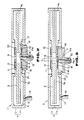
- the disk 5 within the disk cartridge 1 is attached to the disk drive unit 14 arranged and constructed as shown in Fig. 2.
- the disk drive unit 14 includes the center spindle 15 which is engaged in the center apertures 9 provided in the hubs 10 of the disk 5 and to which the drive power is transmitted from a rotary drive source, not shown, either directly or indirectly through transmission means, also not shown.
- the disk table 16 is mounted to the outer periphery of the center spindle 15 for rotation in unison with the center spindle 15.
- the disk table 16 has its upper outer peripheral side formed as a disk supporting surface 17 supporting the major surface of the main body of the disk 5 in the vicinity of the hubs 10.
- the disk table also has a ring-shaped magnet 18 on its inner periphery for generating a uniform magnetic field centered about the center spindle 15 for attracting the metallic plate 12 attached to the hub 10.
- the disk table 16 has a diameter lesser than that of the non-signal recording area provided on the inner periphery of the main body of the disk 5a, so that the signal record area will face to the optical pickup device when the disk table supports the disk 5.
- the disk 5 is lowered onto the disk table 16 of the above disk drive unit 14 so as to follow up with the descent of the cartridge 4 onto the positioning pin 19 as the metallic plate 12 attached to the hubs 10 is attracted by the magnet 18.
- the disk 5 is lowered onto the disk table 16, with the outer periphery of the main body of the disk 5a being guided on the inner wall 4a of the cartridge 4 constituting the disk container 6.
- the one side of the hub 10 abuts on the forward end of the center spindle 15.
- the cartridge 4 is then mounted to the positioning pins 19, with the major surface of the main body of the disk 5a about the hub 10 being supported on the disk supporting surface 17 on the upper side of the disk table 16.
- the disk 5 clears the disk supporting rib 20 within the cartridge 4 so as to be floated within the cartridge 4.
- the disk 5 As the disk 5 is floated within the cartridge 4 with the hub 10 abutting on the forward end of the center spindle 15 and the disk being supported by the disk table 16, the metallic plate 12 attached to the hub 10 is subjected to the force of magnetic attraction by the magnet 17. Under this force of magnetc attraction, the disk 5 is shifted horizontally so that the center opening 9 is aligned with the center spindle 15 to permit the center spindle 15 to be engaged in the center opening 15.
- the disk 5 is mounted to the disk drive unit as the major surface of the main body of the disk 5a around the hub 10 is supported by the overall disk supporting surface 17 on the upper side of the disk table 16. In this manner, the disk 5 is mounted integrally to the disk table 16 for rotation in unison therewith.
- the center spindle 15 is on the same height level as the disk supporting surface 17, as shown in Fig. 2, that is, the forward end of the center spindle 15 is projected above the disk supporting surface 17.
- the one lateral side of the hub 10 abuts on the forward end of the center spindle 15 and the disk 5 is attracted by the magnet 17 simply by the outer peripheral surface of the main body of the disk 5a being guided by the inner peripheral wall of the cartridge 4, such that, even when a relative positioning deviation should be present between the center opening 9 of the disk 5 and the center spindle 15, the disk 5 is attracted by the magnet 17 so as to be attached to the disk table 16 without compensation for such positioning deviation.
- the center spindle 15 When the positioning deviation G1 between the center opening 9 of the disk 5 and the center spindle 15 is not larger than one half the diameter R1 of the center spindle 15, the center spindle 15 is engaged in the opening 9 with the deviation of the center opening 9 being compensated by a guide surface 15a at the forward end of the center spindle 15 which is shaped arcuately when viewed in elevation.
- the conventional practice is to maintain high dimensional accuracy in the outside diameter of the disk 5, the inside diameter of the disk container 6 in the cartridge 4 containing the disk 5 and the position of the positioning holes 13 so as not to produce the deviation in the relative position between the center opening 9 of the disk 5 and the center spindle 15 which is larger than one half the diameter of the center spindle 15 when mounting the disk cartridge 4 within the apparatus.
- the disk 5 and the cartridge 4 are formed separately from each other and hence may undergo fluctuations in the dimensional accuracy resulting from the difference in the manufacture process.
- the disk 5 is formed by a complicated process in which the main body of the disk 5a is formed of synthetic material with the signal recording layer thereon and the hubs 10 is subsequently mounted as by welding to the main body of the disk 5a, it is likely to undergo fluctuations in the outer size or dimension in view of the complicated production process.
- a disk drive device comprising a center spindle engageable in a center opening formed in a disk hub mounted to the center of one surface of a disk, and a disk table including a disk supporting section supporting the one surface of the disk and adapted to make rotation in unison with that of the center spindle, wherein the disk supporting section is projected beyond the forward end of the center spindle and a guide section for the disk hub is provided to the disk supporting section.
- the hub When the disk is lowered towards the disk table, should there be any deviation between the center opening of the hub and the center spindle, the hub is guided along the guide surface provided to the inner periphery of the disk supporting surface of the disk table so as to shift the center opening towards the center spindle to provide for alignment between the center opening and the center spindle, the latter being then engaged in the center opening for attaching the disk onto the disk table.
- a disk drive unit 30 is comprised of a center spindle 31 which is engaged in a center opening 9 provided in a hub 10 of a disk 5 contained in a disk cartridge 1 and to which a drive power is transmitted from a rotary drive source, not shown, either directly or through a transmission system, also not shown, and a disk table 32 attached to the outer periphery of the center spindle 31 for rotation in unison with the center spindle 31.
- This disk table 32 has its upper outer peripheral portion designed as a disk supporting surface 33 supporting the portion of major surface of the main body of the disk 5a around the hub 10 of the disk 5.
- On the inner periphery of the disk table 32 there is mounted a ring-shaped magnet 34 adapted for producing a uniform magnetic field centered about the center spindle 31 for magnetically attracting the metallic plate 12 mounted to the hub 10.
- the disk table has its outside diameter lesser than that of the non-signal record area on the inner peripheral side of the main body of the disk 5a and its inside diameter larger than the outside diameter of the hub 10, so that the hub 10 may be fitted loosely in the disk table 16.
- the disk supporting surface 33 of the disk table 32 is projected above the forward end of the center spindle 31 so that the center spindle 31 is disposed within the interior of the disk table 32.
- the amount of protrusion of the disk supporting surface 33 is selected to be sufficient to permit the center spindle 31 to be engaged in the center opening 9 of the hub 10 when the major surface of the main body of the disk 5a is supported thereon, and is preferably selected to be as large as possible insofar as the center spindle 31 may sufficiently be engaged in the center opening 9.
- a tapered guide surface 35 for the hub 10 is formed on the inner peripheral surface of an upright peripheral wall 34a of the disk table 32 which is the inner periphery of the disk supporting surface 33.
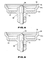
- This guide surface 35 is formed for extending from the side of the disk supporting surface 33 to at least the same height level as the forward end of the center spindle 21.
- the forward end of the center spindle 31 is formed as a center opening guide section 36 having the shape of an arcuately curved surface when seen in side elevation and an angle of inclination substantially equal to 60°.
- center opening guide section 36 at the forward end of the center spindle 21 need not be provided with a large arcuately curved surface, but may be tapered towards the forward end of the spindle. Also the angle of inclination may also be selected appropriately insofar as such angle permits the guide section to be guided within the center opening 9, as shown in Fig. 6.
- the disk cartridge 1 is introduced and placed on the disk drive unit 30 by disk cartridge loading means, not shown, switch is provided along with the disk drive unit 30 to the disk recording and/or reproducing apparatus 30.
- the shutter 8 so far closing the opening 7 of the disk cartridge 1 is slid by the loading means to expose the opening 7 so that the disk 5 may face through this opening 7 to the outside of the cartridge 4.
- the disk 5 within the cartridge 4 follows up with the descent of the cartridge 4 onto the positioning pins 19 provided in the disk recording and/or reproducing apparatus, by virtue of the aforementioned loading means, and is lowered onto the disk table 32, while the metallic plate 12 attached to the hub 10 exposed to the outside through the opening 7 is attracted by the magnet 34.
- the disk 9 is lowered onto the disk table 32, as the outer peripheral surface of the main body of the disk 5a is guided along the inner wall 4a of the disk container 6 within the cartridge 4.
- the cartridge is then supported on the positioning pins 19, with the portion of the major surface of the disk substrate 5a around the hub 10 being supported by the disk supporting surface 17 on the upper side of the disk table 16.
- the disk is caused to clear the rib 20 within the cartridge 4 so as to be floated within the cartridge 4.
- the metallic plate 12 mounted to the hub 10 is attrated by the magnet 34, so that the disk 5 is shifted horizontally until the center opening 9 is aligned with the center spindle 31 to provide for centering of the center spindle 31 relative to the center opening 9 so that the center spindle 31 will be engaged in the center opening 9.
- the disk 5 is attached to the disk drive unit 30 with the major surface portion of the main body of the disk 5a around the hub 10 being supported on the disk supporting surface 33 on the upper side of the disk table 32 in its entirety.
- the disk 5 is mounted in such manner integrally to the disk table 32 so as to be rotated in unison therewith.
- the difference between the inside diameter D1 of the disk table 32 and the outside diameter D2 of the hub 10 is set so as to be not larger than one half the diameter R2 of the center spindle 31, the deviation of the center opening 9 relative to the center spindle 31 can be compensated so as to be within one half the diameter R2 of the center spindle 31 on the condition that the deviation caused is such that the outer peripheral side end of the hub 10 is able to abut on the guide surface 35 formed on the disk table 32, the hub 10 then being guided on the guide surface 35 so as to be shifted towards the center spindle 31.
- the metallic plate 12 mounted to the hub 10 is subjected to the force of attraction of the magnet 34 so that the disk 5 is shifted horizontally until the central opening 5 is aligned with the center spindle 31 to provide for centering of the center opening 9 with respect to the center spindle 31 so that the center spindle 31 will be engaged in the center opening 9 to permit attachment to the disk drive unit.
- the present invention provides a disk drive unit in which the disk substrate supporting surface of the disk table supporting the major surface of the disk substrate and making a rotation in unison with the center spindle is projected beyond the forward end of the center spindle, and in which the inner peripheral side of the disk substrate supporting surface is formed with the guide surface for the hub, the latter may be guided by the guide surface when the disk is lowered onto the disk table, even if a larger deviation exists between the center opening of the hub and the center spindle, so that the center opening may be moved towards the center spindle to provide for centering between the center opening and the center spindle such that the center spindle may be engaged with the center opening to permit disk attachment to the disk table.
- the disk may be positively mounted to the disk as it is correctly centered with respect to the disk.
- the larger tolerance may be allowed in the dimensional accuracy of the disk cartridge, production and designing of the disk cartridge may be facilitated.
Landscapes
- Holding Or Fastening Of Disk On Rotational Shaft (AREA)
Applications Claiming Priority (2)
| Application Number | Priority Date | Filing Date | Title |
|---|---|---|---|
| JP62067021A JP2580590B2 (ja) | 1987-03-20 | 1987-03-20 | デイスク回転駆動装置 |
| JP67021/87 | 1987-05-02 |
Publications (3)
| Publication Number | Publication Date |
|---|---|
| EP0283921A2 true EP0283921A2 (fr) | 1988-09-28 |
| EP0283921A3 EP0283921A3 (en) | 1989-11-15 |
| EP0283921B1 EP0283921B1 (fr) | 1994-01-05 |
Family
ID=13332827
Family Applications (1)
| Application Number | Title | Priority Date | Filing Date |
|---|---|---|---|
| EP88104206A Expired - Lifetime EP0283921B1 (fr) | 1987-03-20 | 1988-03-16 | Dispositif d'entraînement de disque |
Country Status (4)
| Country | Link |
|---|---|
| EP (1) | EP0283921B1 (fr) |
| JP (1) | JP2580590B2 (fr) |
| KR (1) | KR880011754A (fr) |
| DE (1) | DE3886793T2 (fr) |
Cited By (3)
| Publication number | Priority date | Publication date | Assignee | Title |
|---|---|---|---|---|
| EP0488388A2 (fr) * | 1990-11-30 | 1992-06-03 | Mitsui Petrochemical Industries, Ltd. | Disque optique et moyeu pour celui-ci |
| EP0555486A1 (fr) * | 1991-08-02 | 1993-08-18 | Mitsui Petrochemical Industries, Ltd. | Moyeu pour support d'enregistrement optique, et support d'enregistrement optique |
| EP0788103A3 (fr) * | 1996-01-31 | 1998-01-28 | Mitsubishi Denki Kabushiki Kaisha | Dispositif de stockage et cassette à support d'enregistrement |
Families Citing this family (2)
| Publication number | Priority date | Publication date | Assignee | Title |
|---|---|---|---|---|
| NL8700703A (nl) * | 1987-03-26 | 1988-10-17 | Optical Storage Int | Draaitafelinrichting voor een informatieplaat. |
| JP3179458B2 (ja) * | 1989-07-07 | 2001-06-25 | ソニー株式会社 | 光磁気ディスク装置 |
Citations (7)
| Publication number | Priority date | Publication date | Assignee | Title |
|---|---|---|---|---|
| DE2408849A1 (de) * | 1974-02-23 | 1975-09-04 | Licentia Gmbh | Einrichtung zur aufnahme und ausrichtung eines scheibenfoermigen aufzeichnungstraegers |
| EP0026475A1 (fr) * | 1979-10-02 | 1981-04-08 | Licentia Patent-Verwaltungs-GmbH | Procédé et dispositif de centrage et de positionement axial d'un support d'enregistrement en forme de disque |
| EP0086682A1 (fr) * | 1982-02-11 | 1983-08-24 | COMPAGNIE INTERNATIONALE POUR L'INFORMATIQUE CII - HONEYWELL BULL (dite CII-HB) | Mémoire à disques comportant une cartouche amovible pour disque(s) magnétique(s) et cartouche pour disque magnétique |
| US4458278A (en) * | 1982-04-29 | 1984-07-03 | Datacopy Corporation | Disk-centering mechanism for use with a high-density flexible disk |
| AU543176B2 (en) * | 1978-10-16 | 1985-04-04 | Magnetic Peripherals Inc. | Mounting disc on hub |
| EP0230963A2 (fr) * | 1986-01-20 | 1987-08-05 | Kabushiki Kaisha Toshiba | Appareil de traitement de l'information |
| EP0233644A2 (fr) * | 1986-02-20 | 1987-08-26 | Sony Corporation | Disque d'enregistrement optique |
-
1987
- 1987-03-20 JP JP62067021A patent/JP2580590B2/ja not_active Expired - Fee Related
-
1988
- 1988-03-16 DE DE3886793T patent/DE3886793T2/de not_active Expired - Fee Related
- 1988-03-16 EP EP88104206A patent/EP0283921B1/fr not_active Expired - Lifetime
- 1988-03-18 KR KR1019880002862A patent/KR880011754A/ko not_active Application Discontinuation
Patent Citations (7)
| Publication number | Priority date | Publication date | Assignee | Title |
|---|---|---|---|---|
| DE2408849A1 (de) * | 1974-02-23 | 1975-09-04 | Licentia Gmbh | Einrichtung zur aufnahme und ausrichtung eines scheibenfoermigen aufzeichnungstraegers |
| AU543176B2 (en) * | 1978-10-16 | 1985-04-04 | Magnetic Peripherals Inc. | Mounting disc on hub |
| EP0026475A1 (fr) * | 1979-10-02 | 1981-04-08 | Licentia Patent-Verwaltungs-GmbH | Procédé et dispositif de centrage et de positionement axial d'un support d'enregistrement en forme de disque |
| EP0086682A1 (fr) * | 1982-02-11 | 1983-08-24 | COMPAGNIE INTERNATIONALE POUR L'INFORMATIQUE CII - HONEYWELL BULL (dite CII-HB) | Mémoire à disques comportant une cartouche amovible pour disque(s) magnétique(s) et cartouche pour disque magnétique |
| US4458278A (en) * | 1982-04-29 | 1984-07-03 | Datacopy Corporation | Disk-centering mechanism for use with a high-density flexible disk |
| EP0230963A2 (fr) * | 1986-01-20 | 1987-08-05 | Kabushiki Kaisha Toshiba | Appareil de traitement de l'information |
| EP0233644A2 (fr) * | 1986-02-20 | 1987-08-26 | Sony Corporation | Disque d'enregistrement optique |
Cited By (7)
| Publication number | Priority date | Publication date | Assignee | Title |
|---|---|---|---|---|
| EP0488388A2 (fr) * | 1990-11-30 | 1992-06-03 | Mitsui Petrochemical Industries, Ltd. | Disque optique et moyeu pour celui-ci |
| EP0488388A3 (en) * | 1990-11-30 | 1992-08-19 | Mitsui Petrochemical Industries, Ltd. | Hub for optical disk and optical disk |
| EP0555486A1 (fr) * | 1991-08-02 | 1993-08-18 | Mitsui Petrochemical Industries, Ltd. | Moyeu pour support d'enregistrement optique, et support d'enregistrement optique |
| EP0555486A4 (en) * | 1991-08-02 | 1995-02-22 | Mitsui Petrochemical Ind | Hub for optical recording medium and optical recording medium |
| EP0788103A3 (fr) * | 1996-01-31 | 1998-01-28 | Mitsubishi Denki Kabushiki Kaisha | Dispositif de stockage et cassette à support d'enregistrement |
| US5956207A (en) * | 1996-01-31 | 1999-09-21 | Mitsubishi Denki Kabushiki Kaisha | Storage device and recording medium cartridge |
| US5959804A (en) * | 1996-01-31 | 1999-09-28 | Mitsubishi Denki Kabushiki Kaisha | Storage device and recording medium cartridge |
Also Published As
| Publication number | Publication date |
|---|---|
| DE3886793D1 (de) | 1994-02-17 |
| DE3886793T2 (de) | 1994-07-28 |
| KR880011754A (ko) | 1988-10-31 |
| EP0283921B1 (fr) | 1994-01-05 |
| JPS63234443A (ja) | 1988-09-29 |
| JP2580590B2 (ja) | 1997-02-12 |
| EP0283921A3 (en) | 1989-11-15 |
Similar Documents
| Publication | Publication Date | Title |
|---|---|---|
| KR100279095B1 (ko) | 디스크로딩장치 | |
| EP0499413B1 (fr) | Disque et dispositif de blocage de disque | |
| US6034840A (en) | Disk storage apparatus and disk cartridge | |
| US4812937A (en) | Magnetic disk cartridge with improved center plate for disk mounting | |
| EP0283921B1 (fr) | Dispositif d'entraînement de disque | |
| KR19990044187A (ko) | 자기 디스크 장치, 자기 디스크 및 디스크 카트리지 | |
| JPH0817159A (ja) | ディスクカートリッジ | |
| JPS5835772A (ja) | 回転駆動台 | |
| US6147962A (en) | Data storage cartridge having a restraining mechanism | |
| EP0226378B1 (fr) | Appareil à disque de stockage de données | |
| JPH0719464B2 (ja) | デイスクカ−トリツジ | |
| EP0920012B1 (fr) | Cartouche de disque magnetique | |
| EP1543515B1 (fr) | Appareil a unite de disques | |
| JPH0817163A (ja) | ディスクカートリッジ | |
| US6297931B2 (en) | Recording disk with round spindle hole in magnetic hub and prerecorded tracking servo information | |
| JPH04274067A (ja) | ディスクカートリッジ | |
| JP3298651B2 (ja) | 情報信号記録ディスク | |
| JP3063262B2 (ja) | ディスクカートリッジ | |
| KR19990023671A (ko) | 자기 디스크 장치 | |
| JPH103774A (ja) | ディスクカートリッジ | |
| JPH10302431A (ja) | 磁気ディスクカートリッジおよび磁気ディスクドライブ装置 | |
| JPH0467345A (ja) | ディスクカートリッジ装着装置 | |
| JP3531321B2 (ja) | ディスクカートリッジ | |
| JPS6258472A (ja) | 磁気デイスク装置 | |
| JPS63193391A (ja) | デイスク装置 |
Legal Events
| Date | Code | Title | Description |
|---|---|---|---|
| PUAI | Public reference made under article 153(3) epc to a published international application that has entered the european phase |
Free format text: ORIGINAL CODE: 0009012 |
|
| AK | Designated contracting states |
Kind code of ref document: A2 Designated state(s): DE FR GB NL |
|
| PUAL | Search report despatched |
Free format text: ORIGINAL CODE: 0009013 |
|
| AK | Designated contracting states |
Kind code of ref document: A3 Designated state(s): DE FR GB NL |
|
| 17P | Request for examination filed |
Effective date: 19900125 |
|
| 17Q | First examination report despatched |
Effective date: 19910516 |
|
| GRAA | (expected) grant |
Free format text: ORIGINAL CODE: 0009210 |
|
| AK | Designated contracting states |
Kind code of ref document: B1 Designated state(s): DE FR GB NL |
|
| REF | Corresponds to: |
Ref document number: 3886793 Country of ref document: DE Date of ref document: 19940217 |
|
| PGFP | Annual fee paid to national office [announced via postgrant information from national office to epo] |
Ref country code: FR Payment date: 19940310 Year of fee payment: 7 Ref country code: DE Payment date: 19940310 Year of fee payment: 7 |
|
| PGFP | Annual fee paid to national office [announced via postgrant information from national office to epo] |
Ref country code: NL Payment date: 19940331 Year of fee payment: 7 Ref country code: GB Payment date: 19940331 Year of fee payment: 7 |
|
| ET | Fr: translation filed | ||
| PLBE | No opposition filed within time limit |
Free format text: ORIGINAL CODE: 0009261 |
|
| STAA | Information on the status of an ep patent application or granted ep patent |
Free format text: STATUS: NO OPPOSITION FILED WITHIN TIME LIMIT |
|
| 26N | No opposition filed | ||
| PG25 | Lapsed in a contracting state [announced via postgrant information from national office to epo] |
Ref country code: GB Effective date: 19950316 |
|
| PG25 | Lapsed in a contracting state [announced via postgrant information from national office to epo] |
Ref country code: NL Effective date: 19951001 |
|
| GBPC | Gb: european patent ceased through non-payment of renewal fee |
Effective date: 19950316 |
|
| PG25 | Lapsed in a contracting state [announced via postgrant information from national office to epo] |
Ref country code: FR Free format text: LAPSE BECAUSE OF NON-PAYMENT OF DUE FEES Effective date: 19951130 |
|
| NLV4 | Nl: lapsed or anulled due to non-payment of the annual fee |
Effective date: 19951001 |
|
| PG25 | Lapsed in a contracting state [announced via postgrant information from national office to epo] |
Ref country code: DE Effective date: 19951201 |
|
| REG | Reference to a national code |
Ref country code: FR Ref legal event code: ST |